Executive Summary
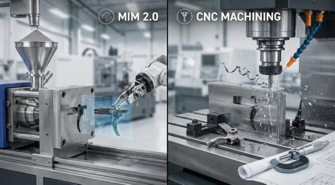
The small arms manufacturing sector is currently navigating a profound structural paradigm shift, driven by the dual imperatives of optimizing high-volume production economics and adhering to stringent operational performance specifications. Historically, the fabrication of mission-critical fire control group components—specifically hammers, sears, disconnectors, and triggers—relied exclusively on the subtractive computer numerical control (CNC) machining of hardened tool steels from billet, or investment casting followed by secondary precision machining operations. However, the advent and maturation of advanced Metal Injection Molding (often referred to within the industry as MIM 2.0) has fundamentally disrupted this traditional manufacturing matrix, offering unprecedented geometric complexity at a fraction of the per-unit cost at scale.
By leveraging highly sophisticated feedstock rheology, tightly controlled catalytic and thermal debinding atmospheres, and super-solidus liquid phase sintering mechanisms, modern MIM processes can consistently achieve near-wrought densities exceeding 96 percent. When coupled with secondary densification processes such as Hot Isostatic Pressing (HIP), component density can be driven to 99 percent or greater, severely mitigating the historical weaknesses associated with powdered metallurgy.
This intelligence report delivers an exhaustive, cross-source comparative analysis of MIM-processed 17-4 PH precipitation-hardening stainless steel against CNC-machined S7 shock-resisting tool steel. The scope of this analysis encompasses physical metallurgy, statistical failure rates, porosity-induced fatigue mechanics, and supply chain logistics. Evidence indicates that while CNC-machined S7 tool steel remains the technologically superior choice for low-volume, ultra-high-impact applications due to its anisotropic grain structure, extreme impact toughness, and absolute lack of internal voids, MIM 17-4 PH—specifically when aged to the H900 heat-treated condition—provides a statistically viable, economically superior alternative for mass-market high-volume production. High-round-count reliability testing demonstrates that geometrically optimized MIM fire control components exhibit failure rates as low as 0.02 to 0.05 percent over 50,000 actuation cycles.
Furthermore, a comprehensive supply chain and cost-benefit analysis reveals that MIM fundamentally alters unit economics at scale. By reducing material waste from over 50 percent in traditional subtractive machining to less than 5 percent, and by amortizing upfront tooling investments over high-volume runs (exceeding 10,000 units), manufacturers can achieve per-unit cost reductions of 60 to 80 percent. The economic crossover point heavily favors MIM for intricate components, such as sears and disconnectors, which would otherwise require costly multi-axis CNC milling setups.
This report provides defense contractors, tier-2 manufacturers, and C-suite executives with the objective, data-grounded intelligence required to navigate material selection matrices, mitigate global supply chain vulnerabilities, and optimize production methodologies for next-generation small arms platforms.
1.0 Introduction to Small Arms Manufacturing Dynamics
The evolution of metal injection molding from a novel process suited only for non-critical, low-stress commercial applications into a dominant manufacturing force for defense components represents a critical leap in materials engineering.1 For decades, the firearms industry viewed powdered metallurgy and early-generation MIM with distinct skepticism. Early implementations in the late 20th century were plagued by inconsistent dimensional shrinkage, improper carbon control, and severe internal porosity, leading to highly publicized catastrophic failures of hammers and sears in production sidearms and rifles.2 These failures cemented a persistent industry bias favoring fully machined billet or forged components.
However, the modern defense and commercial small arms market is characterized by extreme price sensitivity and a demand for highly ergonomic, mechanically complex weapon systems. The internal geometries of a modern striker-fired pistol or a select-fire rifle’s trigger group contain intricate blind pockets, compound radii, and asymmetrical safety engagement surfaces. To machine these features from a solid block of high-alloy tool steel requires specialized 5-axis CNC machining centers, extensive programming time, multiple costly workholding setups, and continuous cutting tool replacement due to abrasive wear.3 The subtractive process is inherently time-intensive and produces massive amounts of material waste, which is economically punishing when utilizing expensive, high-performance alloys.4
MIM 2.0 emerged as the technological solution to this economic bottleneck. By combining the geometric freedom of plastic injection molding with the mechanical properties of advanced metallurgy, MIM allows manufacturers to produce net-shape or near-net-shape components in massive volumes.5 Defense contractors now represent the second-largest consumer base for MIM components globally, trailing only the automotive sector, with stainless steel alloys accounting for over half of all material usage.3 The core differentiator between legacy MIM and modern MIM 2.0 lies in the rigorous, data-driven control of process variables, specifically the reduction of residual porosity, the precise management of atmospheric chemistry during sintering, and the stabilization of dimensional shrinkage across massive production lots.
2.0 Metal Injection Molding (MIM) 2.0: Process Engineering and Defect Mitigation
To understand the mechanical capabilities and limitations of a MIM fire control component, one must first dissect the manufacturing process. MIM is a multi-stage operation involving feedstock preparation, injection molding, debinding, and sintering. Each phase introduces specific variables that directly dictate the final density, microstructural integrity, and mechanical fatigue life of the part.6
2.1 Feedstock Formulations and Powder Morphology
The MIM process begins with the compounding of fine metal powders with a multi-component polymeric binder system, typically consisting of primary waxes and a secondary polymer backbone.1 The physical characteristics of the metal powder are the foundational determinant of final part quality. In modern MIM 2.0 applications, manufacturers utilize powders with diameters typically less than 20 micrometers.5
A critical advancement in modern MIM is the transition from water-atomized powders to gas-atomized powders.8 Water atomization involves spraying a stream of molten metal with high-pressure water jets, which cools the metal rapidly but results in highly irregular, jagged particle shapes. When these irregular particles are compacted and sintered, they leave behind angular voids. Conversely, gas atomization utilizes inert gases (such as argon or nitrogen) to disperse the molten metal. Because the cooling rate is slightly slower and occurs in a gaseous medium, surface tension pulls the droplets into nearly perfect spheres before they solidify.
Spherical gas-atomized powders provide a significantly higher packing density within the initial “green part” and exhibit superior rheological flow during the injection molding phase. More importantly, during sintering, spherical powders coalesce to form smooth, rounded residual pores.8 In fracture mechanics, the shape of an internal void is just as critical as its volume. Angular pores act as severe stress multipliers, creating sharp initiation points for micro-cracks under impact loading. Rounded pores distribute applied mechanical stress much more evenly across the surrounding metallic matrix, resulting in a 10 percent increase in overall tensile strength and notably higher ductility compared to water-atomized equivalents.8
2.2 The Sintering Mechanism and Dimensional Control
During the injection phase, the feedstock is molded under high pressure into a multi-cavity tool. Because the binder will eventually be removed, the mold cavities are machined precisely 18 to 22 percent larger than the final specified dimensions of the component to account for volumetric shrinkage.7
Following injection, the “green part” undergoes debinding. This involves thermal, catalytic, or solvent-based processes to extract the primary wax binders, leaving a semi-porous “brown part” held together solely by the polymer backbone.6 If the debinding rate is too aggressive, the rapid volatilization and expansion of the binder gases can cause microscopic internal ruptures and blistering. These defects will persist through the final thermal processing and serve as primary failure points in a finished sear or hammer.
Sintering is the thermodynamic process wherein the brown part is heated in a controlled-atmosphere furnace (often utilizing hydrogen, nitrogen, or a vacuum) to temperatures just below the liquidus point of the primary alloy—typically between 1250 degrees Celsius and 1350 degrees Celsius for 17-4 PH stainless steel.10 For high-carbon tool steels like S7 or M2, the process utilized is Super-Solidus Liquid Phase Sintering (SSLPS).11 In SSLPS, the temperature is raised precisely to the point where localized melting occurs exclusively at the grain boundaries, creating a microscopic liquid film. Capillary forces then pull the solid particles together, driving rapid densification and the expulsion of void spaces.11
2.3 Residual Porosity and Hot Isostatic Pressing (HIP)
In standard high-quality MIM processing, the resulting component achieves between 95 and 97 percent of its theoretical maximum density.5 The remaining 3 to 5 percent consists of isolated, internal microporosity.12 While a 96 percent dense part is entirely adequate for static, non-critical applications, firearm fire control groups are subjected to violent, dynamic, and cyclic percussive loading.
To bridge the mechanical performance gap between MIM components and fully dense wrought billet materials, advanced defense programs employ Hot Isostatic Pressing (HIP) as a post-sintering operation. HIP subjects the sintered component to simultaneous elevated temperatures and multi-directional isostatic inert gas pressure (frequently argon at pressures exceeding 100 MPa).13 This extreme thermo-mechanical environment forces the material to yield plastically on a microscopic scale, physically collapsing the internal voids and facilitating metallurgical diffusion bonding across the pore boundaries.13
The application of HIP elevates the component density to 99 percent or greater, effectively eliminating the primary source of fatigue crack initiation. For highly stressed parts, such as 17-4 PH stainless steel components, HIP treatment can increase the fatigue endurance limit by a factor of 2.25 (from 200 MPa to 450 MPa) and extend the total high-stress fatigue life by 1,000 to 3,000 percent.12
3.0 Metallurgical Profiling: 17-4 PH Stainless Steel vs. S7 Tool Steel
The selection of the appropriate alloy for a fire control group is a delicate engineering compromise involving ultimate tensile strength, yield strength, impact toughness, abrasive wear resistance, corrosion resistance, and baseline manufacturability. Within this context, 17-4 PH stainless steel (frequently utilized in MIM) and S7 tool steel (frequently utilized in premium CNC machining) represent two vastly different metallurgical philosophies.14
3.1 MIM 17-4 PH Precipitation-Hardening Stainless Steel
17-4 PH (designated as UNS S17400 or Type 630) is a precipitation-hardening martensitic stainless steel.15 Its nominal chemical composition is carefully balanced, featuring 15.0 to 17.5 percent Chromium, 3.0 to 5.0 percent Nickel, 3.0 to 5.0 percent Copper, 0.15 to 0.45 percent Columbium (Niobium) plus Tantalum, and a maximum carbon content strictly limited to 0.07 percent.16 The defining mechanical properties of this alloy are not derived merely from carbon martensite, but from a highly controllable, multi-stage heat treatment process.
When subjected to a solution annealing treatment (Condition A), the alloy is heated to approximately 1040 degrees Celsius (1900 degrees Fahrenheit) and rapidly cooled to below 32 degrees Celsius.18 This step dissolves the copper into the matrix, transforming the microstructure into a supersaturated solid solution of low-carbon martensite. In Condition A, the material is relatively ductile, softer (approximately 34 HRC), and highly machinable.19
To achieve the massive tensile strength required for firearm components, the material undergoes an aging (precipitation hardening) process. The most common state for MIM firearm components is the H900 condition, achieved by heating the part to 900 degrees Fahrenheit (482 degrees Celsius) for precisely one hour, followed by air cooling.20 During this aging phase, microscopic copper-rich particles precipitate out of the solid solution and disperse uniformly throughout the martensitic crystal lattice.22 These precipitates act as physical barriers to dislocation movement within the atomic structure. Because plastic deformation in metals occurs via the slip of these dislocations, impeding their movement drastically increases the yield strength and ultimate tensile strength of the material.21
In the MIM H900 condition, properly processed 17-4 PH exhibits the following baseline mechanical properties:
- Ultimate Tensile Strength (UTS): 1150 to 1310 MPa 15
- Yield Strength (0.2% offset): 1050 to 1170 MPa 15
- Elongation at Break: 6 to 10 percent 23
- Macro Hardness: 33 to 43 Rockwell C (HRC) 10
- Density: 7.60 to 7.75 g/cm3 15
Beyond sheer mechanical strength, the high chromium content provides an exceptional passive oxide layer, granting the material substantial, native resistance to environmental corrosion. This is a critical logistical factor for defense firearms exposed to maritime environments, high humidity, and acidic propellant residues, effectively eliminating the need for secondary anti-corrosion coatings.26
3.2 CNC-Machined S7 Shock-Resisting Tool Steel
S7 (designated as UNS T41907) is a premium, general-purpose, air-hardening, shock-resisting tool steel.17 Its metallurgical composition is distinctly tailored for extreme, repetitive impact environments: 0.45 to 0.55 percent Carbon, 3.0 to 3.5 percent Chromium, 1.3 to 1.8 percent Molybdenum, and 0.2 to 1.0 percent Silicon.17 Unlike 17-4 PH, S7 lacks the nickel and the requisite 10.5+ percent chromium content required to form a regenerative passive oxide layer.17 Consequently, S7 is highly susceptible to atmospheric rust and galvanic corrosion unless protected by robust surface treatments such as Black Oxide, QPQ Salt Bath Nitriding, or Physical Vapor Deposition (PVD) coatings.30
The defining characteristic of S7 tool steel is its unparalleled impact toughness at high hardness levels.30 When austenitized at 1725 degrees Fahrenheit (940 degrees Celsius) and quenched in air or warm oil, it forms a highly stressed, carbon-rich martensitic structure.31 Subsequent tempering operations relieve the internal stresses while dialing in the desired hardness. For firearm hammers, extractors, and bolt carriers, S7 is typically tempered at roughly 400 to 500 degrees Fahrenheit to achieve an optimal working “sweet spot” hardness of 54 to 58 HRC.33
At this hardness, fully dense wrought S7 exhibits formidable metrics:
- Ultimate Tensile Strength (UTS): 2030 to 2200 MPa 17
- Yield Strength: 1550 to 2050 MPa 34
- Macro Hardness: 54 to 60 HRC 33
- Impact Energy (Charpy V-Notch): 13.6 to 16.9 Joules 31
- Elastic Modulus: 190 to 207 GPa 17
- Density: 7.83 g/cm3 29
The synergistic combination of high carbon and molybdenum allows S7 to maintain its geometric integrity under the violent percussive forces generated during the cycling of a firearm action.35 When a hammer strikes a firing pin, or when a bolt carrier abruptly forces a hammer rearward during the extraction stroke, the material must absorb the kinetic energy without undergoing plastic deformation (yielding) or brittle fracture (shattering). CNC machining S7 from forged or rolled billet ensures a continuous, unbroken, and anisotropic grain flow, maximizing the structural integrity of the component along its primary load-bearing axes.9
3.3 Comparative Mechanical Properties Analysis
To objectively evaluate these materials for fire control applications, a direct comparison of their static and dynamic mechanical properties is required. Table 1 outlines the fundamental structural differences between MIM 17-4 PH (H900 condition) and CNC Machined S7 Tool Steel (Hardened).
Table 1: Metallurgical Comparison of Fire Control Group Materials
| Property Metric | MIM 17-4 PH Stainless Steel (H900) | CNC Machined S7 Tool Steel (Hardened) | Engineering Impact on Fire Control Design |
| Ultimate Tensile Strength | 1150 – 1310 MPa | 2030 – 2200 MPa | S7 offers a vastly higher threshold before catastrophic fracture, ideal for extreme high-stress geometries. |
| Yield Strength | 1050 – 1170 MPa | 1550 – 2050 MPa | S7 resists plastic deformation under extreme impact, ensuring sear geometry remains pristine over high round counts. |
| Macro Hardness | 33 – 44 HRC | 54 – 60 HRC | S7 provides superior abrasive wear resistance on sliding contact surfaces, preventing “hammer follow” malfunctions. |
| Corrosion Resistance | Excellent (Native passive layer) | Poor (Requires secondary coating) | 17-4 PH significantly reduces field maintenance burdens and prevents rust-induced tolerance stacking. |
| Microstructural Integrity | Isotropic, 1-5% residual porosity | Anisotropic grain flow, 100% dense | Billet S7 provides predictable high-cycle fatigue life; MIM requires strict density control and potential HIP treatment. |
| Impact Toughness | Moderate (Reduced by porosity) | Exceptional (13.6 – 16.9 Joules) | S7 excels in components subjected to violent kinetic shocks, such as strikers, hammers, and extractors. |
4.0 Statistical Failure Rates and Fatigue Mechanics in Fire Control Groups
The theoretical, static mechanical properties of an alloy dictate its baseline load-bearing capabilities, but the true measure of a component’s viability in small arms is determined by its statistical failure rate in dynamic, operational environments. Fire control groups are subjected to cyclic loading regimens; therefore, static yield strength is ultimately less critical than the material’s fatigue limit and its resistance to crack propagation over time.
4.1 Fatigue Mechanics: Porosity as a Microscopic Stress Concentrator
Fatigue failure occurs when a material is subjected to repeated loading and unloading cycles at stress levels well below its ultimate tensile strength. The physical process involves three distinct stages: crack initiation, crack propagation, and final catastrophic rupture.36
In traditional CNC-machined wrought steels (such as S7 billet), the material is essentially 100 percent dense.9 Crack initiation therefore relies heavily on surface imperfections, such as deep machining marks, sharp internal geometric radii, or localized material inclusions. In MIM components, the mechanics of failure differ fundamentally due to residual porosity. Even at a highly controlled 96 percent density, the remaining 4 percent of void space acts as an internal network of microscopic stress concentrators.9
According to classical fracture mechanics, the stress concentration factor at the edge of an internal pore is significantly higher than the nominal stress applied to the bulk material. When a MIM hammer strikes a firing pin, the macroscopic force is transmitted through the metallic matrix. At the boundary of an internal pore, the localized stress may suddenly exceed the material’s yield point, causing microscopic plastic deformation and initiating a micro-crack.37 Over thousands of firing cycles, these micro-cracks propagate, linking adjacent pores together until the remaining contiguous cross-sectional area can no longer support the mechanical load. This results in a sudden, brittle-like fracture, often without any prior visible deformation.9
This microstructural reality dictates that the fatigue endurance limit of a standard, as-sintered MIM component is generally 15 to 20 percent lower than that of its wrought equivalent.9 For standard MIM 17-4 PH, the fatigue limit at 10 million cycles hovers around 200 MPa, compared to over 450 MPa for wrought materials.13
4.2 Component-Specific Failure Modes
The mode of failure differs depending on the component’s function within the kinematic chain of the firearm.
Hammers and Strikers: The hammer is subjected to violent, high-velocity impact forces.9 When a MIM hammer fails, it typically fractures at the thinnest cross-section (the strut or the neck) due to impact fatigue.38 If the sintering process left an unacceptably large void or carbon inclusion near the surface of the neck, the stress of the bolt carrier driving the hammer rearward will initiate a crack at that void, propagating rapidly until the strut shears entirely.39 Conversely, an S7 tool steel hammer, leveraging its high impact toughness and complete lack of porosity, will absorb the shock wave elastically, effectively yielding an infinite service life under normal firing conditions.9
Sears and Disconnectors: The sear governs the trigger pull weight and critical safety engagements. It is subjected to constant shear stress and abrasive sliding friction.3 Failure in a sear usually manifests not as a catastrophic fracture, but as accelerated wear and edge rounding. If a MIM 17-4 PH sear is insufficiently hardened (e.g., measuring under 35 HRC) or possesses poor carbon control, the sharp, highly defined geometric edge required for a crisp trigger break will gradually round off under the pressure of the hammer hooks.40 This deformation leads to an unsafe mechanical condition known as “hammer follow,” where the weapon may discharge involuntarily or transition to uncontrolled automatic fire. Machined S7 sears, hardened to 58 HRC, are highly resistant to this abrasive wear, maintaining their precise dimensional geometry over decades of use.33
4.3 MTBF and High-Round-Count Testing Protocols
In the context of small arms reliability engineering, Mean Time Between Failures (MTBF) is more accurately expressed as Mean Cycles Between Failures (MCBF), measured in the total number of rounds fired before a hardware failure mandates armorer intervention or component replacement.41
Industry-standard reliability testing protocols for modern military and law enforcement sidearms routinely require 20,000 to 50,000 round endurance assessments.42 While early MIM parts suffered from high failure rates due to poor density control, aggregated data from tier-1 manufacturers utilizing MIM 2.0 processes provides a transparent view of component reliability when subjected to rigorous quality control.38
Extensive 50,000-round operational torture tests on modern MIM fire control groups reveal exceptionally low statistical failure rates for critical components 38:
- Triggers and Hammers: 0.02 percent statistical failure rate.
- Sears: 0.05 percent statistical failure rate.
- Slide Stops: 0.08 percent statistical failure rate.
- Firing Pins / Strikers: 1.2 percent failure rate (elevated due to dry-fire conditions).
- Extractors: 2.8 percent failure rate (due to extreme flexural and shear stresses during casing extraction).
These empirical metrics indicate that while MIM parts inherently possess lower theoretical fatigue limits than billet counterparts, a properly engineered MIM component—where the physical geometry is designed specifically to account for the material’s mechanical properties, utilizing thicker cross-sections and larger radii—operates well within the required safety margins for standard military and civilian applications.38
The data visualization above illustrates the engineering trade-off. CNC-machined S7 tool steel offers a massive surplus of static strength (approaching 2050 MPa) and a dynamic fatigue life extending beyond 75,000 cycles, rendering it effectively indestructible under normal firearm kinematics. However, MIM 17-4 PH, despite its lower UTS of 1150 MPa, successfully clears the 50,000-cycle threshold demanded by stringent military testing, proving its functional viability.
Table 2: Data Backup for Performance Delta Chart
| Material Process | Ultimate Tensile Strength (MPa) | Demonstrated Lifecycle Reliability (MCBF / Cycles) |
| MIM 17-4 PH (H900) | 1,150 | > 50,000 |
| CNC S7 Tool Steel | 2,050 | > 75,000 |
5.0 Supply Chain Logistics, Scalability, and Defense Procurement
The decision by a defense contractor or commercial manufacturer to transition from CNC machining to metal injection molding is rarely driven by a desire for absolute maximum metallurgical performance. Rather, it is a highly calculated economic strategy designed to optimize supply chain efficiency, drastically reduce unit costs, and scale production rapidly to meet market demand.1
5.1 Capital Expenditures and Volume Break-Even Analysis
The economics of MIM are characterized by high initial capital expenditures (CapEx) and extremely low recurring unit costs.43 The engineering, metallurgical formulation, mold flow simulation, and fabrication of the hardened steel injection molds can require an initial tooling investment ranging from $50,000 to over $150,000 depending on part complexity.44 Consequently, MIM is economically prohibitive for small production runs, custom firearm builds, or agile prototype development.43
Conversely, CNC machining requires virtually zero dedicated upfront tooling investment, aside from standard end mills and custom workholding fixtures.43 The cost of CNC machining is heavily weighted toward variable recurring costs: bulk material stock, cutting tool wear, expensive machine-hour rates, and highly skilled operator labor.43
The economic break-even point between these two manufacturing technologies typically occurs between 10,000 and 20,000 units, heavily dependent on the geometric complexity of the component.43
- Complex Geometries: A highly intricate disconnector with multiple undercuts, thin-walled structures, blind pockets, and non-linear surfaces might require specialized 5-axis CNC machining and multiple workholding setups, driving the per-part cost to $15.00 or higher. The identical part produced via MIM might cost $2.50 per unit.44 In this scenario, the massive $12.50 part-delta allows the initial $100,000 tooling cost to be amortized rapidly, lowering the break-even point to roughly 8,000 units.
- Simple Geometries: For a simple, cylindrical firing pin that can be turned rapidly on a Swiss-style CNC lathe in seconds, the CNC unit cost may be so low that the MIM tooling investment never reaches a break-even point within the standard product lifecycle.47
At sustained production volumes exceeding 25,000 to 50,000 units annually, MIM generally provides a sweeping 60 to 80 percent total cost reduction compared to traditional subtractive machining.48
5.2 Material Utilization and Scrap Reduction Equivalencies
In an era defined by volatile commodity markets, tariffs, and fragile global supply chains, material utilization has emerged as a critical performance metric for defense contractors.49 Traditional subtractive manufacturing is inherently inefficient and wasteful. Machining a complex hammer or sear from a solid block of premium S7 billet steel can result in a material scrap rate exceeding 50 to 70 percent.48 This scrap, converted into metal chips and contaminated with cutting fluids, must be collected and recycled at a mere fraction of its original procurement value.4
Metal injection molding, by contrast, is a near-net-shape additive-style process. The feedstock injected into the mold represents the exact volume of metal required for the final part, plus the sacrificial binder.4 The material utilization rate for MIM routinely exceeds 95 to 98 percent.48 Furthermore, the runner systems and sprues from the injection molding process can often be reground and recycled directly back into the feedstock hopper, driving effective material loss to near zero.48 For expensive, high-alloy stainless steels like 17-4 PH, or exotics like Titanium, this massive reduction in raw material consumption provides a profound economic advantage and insulates the manufacturer from macroeconomic material price shocks.48
5.3 Lead Times, Scalability, and Quality Assurance
Supply chain resilience and responsiveness are primary concerns for the defense industrial base.50 Traditional CNC machining presents linear scaling challenges. To double production capacity from 10,000 to 20,000 units per month, a manufacturer must procure additional half-million-dollar CNC milling centers, lease more operational floor space, and hire additional skilled machinists, which can take months.51
MIM offers exponential scalability. Once the mold is validated and the thermodynamic process parameters are locked, scaling production simply requires utilizing multi-cavity molds.52 A 16-cavity tool can produce 16 components in a single 30-second injection cycle, vastly outpacing machining times.52
However, the initial supply chain lead time is a known vulnerability for MIM. Procuring MIM tooling, dialing in the highly sensitive 18 percent shrinkage factors, establishing the sintering thermal profiles, and completing the First Article Inspection (FAI) can span 8 to 16 weeks.3 If an engineering design flaw is discovered during this period, modifying the hardened steel mold is expensive and time-consuming. CNC machining allows for agile, on-the-fly digital CAD/CAM design iterations, making it the superior choice for low-rate initial production (LRIP) and iterative developmental phases.
Defense contractors utilizing MIM must also maintain stringent compliance protocols, including ITAR registration, ISO 9001 quality management systems, and Cybersecurity Maturity Model Certification (CMMC).3 To mitigate the risk of substandard, highly porous MIM components entering the supply chain, modern defense quality assurance protocols mandate rigorous statistical process control (SPC).38 This includes tracking dimensional tolerances to ensure process capability indices of Cp > 1.33 and Cpk > 1.67, alongside batch-level destructive tensile testing (ASTM E8) and non-destructive Resonant Acoustic Method (RAM) evaluations to detect internal void anomalies and density variations prior to assembly.38
6.0 Emerging Technologies: Additive Manufacturing and Hybrid Methodologies
The manufacturing landscape is continually evolving, with new technologies seeking to bridge the gap between the rapid prototyping agility of CNC machining and the high-volume economics of MIM.
6.1 Additive Manufacturing: BPE and Metal FFF
Additive manufacturing (3D printing) of metals has gained significant traction, specifically methodologies like Bound Powder Extrusion (BPE) and Metal Fused Filament Fabrication (FFF).55 These processes utilize a metal-polymer filament structurally similar to MIM feedstock, which is extruded layer-by-layer to form a green part, followed by identical debinding and sintering steps.57
While BPE allows for the creation of 17-4 PH stainless steel parts without the $100,000 upfront mold investment, the process currently suffers from critical metallurgical flaws. Empirical studies indicate that extrusion-based AM methods result in significant decreases in tensile and fatigue strength compared to MIM or Selective Laser Melting (SLM).57 The layer-by-layer pathing scheme creates rough surfaces and highly directional internal voids that act as severe local stress risers, casting doubt on the immediate viability of Metal FFF for highly stressed structural firearms components.57 Until internal defect rates are drastically reduced, MIM remains the superior technology for powdered metal part generation.
6.2 The Hybrid Manufacturing Model
The most effective modern strategy employed by elite tier-1 manufacturers is a hybrid manufacturing model that leverages the economic efficiency of MIM alongside the absolute precision of CNC machining.47 Recognizing that MIM generally holds global tolerances of +/- 0.3 to 0.5 percent of the nominal dimension, engineers design “near-net-shape” MIM blanks.3
These blanks are molded with a few thousandths of an inch of extra material on the most critical functional surfaces—such as the microscopic sear engagement ledge on a hammer. After sintering and heat treatment (bringing the part to H900 condition), the component is subjected to a single, rapid CNC grinding or wire EDM (Electrical Discharge Machining) operation.47 This subtractive finishing step cuts the final engagement surface to a flawless tolerance of +/- 0.025 mm.47
This hybrid approach captures 70 to 85 percent of the massive cost savings associated with MIM while delivering the exact kinematic precision and surface finish of a fully machined billet component.47
7.0 Strategic Conclusions
The empirical data and metallurgical profiling definitively establish that both CNC-machined S7 tool steel and MIM 17-4 PH stainless steel possess distinct, highly specific utility within the small arms manufacturing sector.
CNC machining S7 tool steel from billet remains the gold standard for parts requiring ultimate impact toughness and infinite fatigue life under extreme stress. Its 100 percent dense, anisotropic grain structure prevents the rapid crack propagation seen in porous materials, making it indispensable for low-volume, ultra-premium weapon systems where unit cost is secondary to absolute survivability.
Conversely, MIM 2.0 processing of 17-4 PH stainless steel has proven itself as a highly capable, economically transformative technology for mass production. When paired with stringent quality control, optimized geometric design to account for lower fatigue limits, and secondary HIP densification, MIM parts routinely exceed 50,000-cycle MTBF requirements. With a failure rate of just 0.02 to 0.05 percent for fire control components, the process provides an acceptable level of operational reliability while reducing manufacturing costs by up to 80 percent and slashing material waste to near zero.
The future of defense small arms manufacturing relies not on choosing one technology over the other, but on deploying a hybrid approach—utilizing the rapid scalability of MIM for the bulk geometry, and relying on precision CNC machining only for the final, critical contact surfaces.
Appendix: Methodology
The findings in this intelligence report were synthesized using a rigorous, cross-source analytical framework relying on documented metallurgical data, commercial manufacturing case studies, and industry-standard kinetic testing protocols.
- Material Data Sourcing: Mechanical properties for 17-4 PH stainless steel and S7 tool steel were extracted from standardized materials databases (including ASTM A564 for 17-4 PH, and AISI specifications for S7). Primary comparison vectors included Ultimate Tensile Strength (UTS), Yield Strength (0.2% offset), Rockwell Hardness (HRC), Elastic Modulus, and Charpy V-Notch impact energies.
- Proxy Metrics for Reliability: Mean Time Between Failures (MTBF) and Mean Cycles Between Failures (MCBF) were established using standard 50,000-round live-fire endurance testing data as a proxy. The aggregated failure rates (0.02% to 0.05% for sears and hammers) provided the statistical foundation for assessing the viability of MIM components in cyclic, high-stress environments compared to theoretical fatigue limits.
- Economic Modeling Assumptions: Cost-benefit ratios, break-even thresholds (calculated at 10,000 units), and material utilization percentages (95% to 98% for MIM vs. <50% for subtractive CNC) were derived from standard industry cost-accounting models regarding tooling amortization, per-part material costs, and high-volume machine-hour rates.
- Fracture Mechanics: The correlation between residual porosity (measured via relative density percentages) and fatigue limit degradation was established using foundational principles of materials science, specifically regarding localized stress concentration factors at internal void boundaries and their role in micro-crack initiation during cyclic loading.
Need a deeper dive into your supply chain vulnerabilities, process-optimization, or a custom engineering analysis? Contact Ronin’s Grips Analytics for commissioned reporting and B2B consulting.
Please share the link on Facebook, Forums, with colleagues, etc. Your support is much appreciated and if you have any feedback, please email us in**@*********ps.com. If you’d like to request a report or order a reprint, please click here for the corresponding page to open in new tab.
Sources Used
- Metal Injection Molding in the Defense Industry – Nichols Portland, Inc., accessed February 24, 2026, https://nicholsportlandinc.com/blog/metal-injection-molding-in-the-defense-industry
- Why Does Metal Injection Molding Firearms Manufacturing Divide The Gun Community?, accessed February 24, 2026, https://www.abismould.com/info/why-does-metal-injection-molding-firearms-manu-103184640.html
- How Does Metal Injection Molding Transform Defense Manufacturing?, accessed February 24, 2026, https://www.abismould.com/info/how-does-metal-injection-molding-transform-def-103186495.html
- All About MIM–Part Two – RevolverGuy.Com, accessed February 24, 2026, https://revolverguy.com/all-about-mim-part-two/
- Comparing Metal Injection Molding & Powdered Metallurgy – Optimim, accessed February 24, 2026, https://www.optimim.com/resources/article/comparing-metal-injection-molding-and-powdered-metallurgy
- Manufacturing Process: Metal Injection Molding (MIM) – Lumafield, accessed February 24, 2026, https://www.lumafield.com/article/manufacturing-process-metal-injection-molding-mim
- Kinetics MIM 17-4PH Stainless Steel (H900 Condition) – MatWeb, accessed February 24, 2026, https://asia.matweb.com/search/SpecificMaterialText.asp?bassnum=NKINET04
- A review on the production of 17-4PH parts using press and sinter technology – PMC, accessed February 24, 2026, https://pmc.ncbi.nlm.nih.gov/articles/PMC10364798/
- Comprehensive Analysis of Tool Steel Metal Injection Molding (MIM) Technology, accessed February 24, 2026, https://mikeshoppingroom.com/tool-steel-mim-metal-injection-molding/
- MIM 17-4 – Stainless Steel 17-4 PH – ZCMIM, accessed February 24, 2026, https://www.zcmim.com/mim-17-4/
- Tool Steel MIM – ZCMIM, accessed February 24, 2026, https://www.zcmim.com/tool-steel-mim/
- How Strong Are MIM Parts? A Technical Analysis of Mechanical Performance, accessed February 24, 2026, https://mikeshoppingroom.com/are-mim-parts-strong-technical-analysis/
- Metal Injection Molding with Hot Isostatic Pressing: Complete Engineering Guide to Achieving 99.9% Density, accessed February 24, 2026, https://mikeshoppingroom.com/metal-injection-molding-with-hot-isostatic-pressing/
- Tool Steels in Metal Injection Molding | APP, accessed February 24, 2026, https://advancedpowderproducts.com/metal-injection-molding-materials/tool-steels
- MIM 17-4 PH – Neway Precision, accessed February 24, 2026, https://www.newayprecision.com/services/metal-injection-molding/mim-17-4-ph
- 17-4 PH Stainless Steel – Progressive Alloy Steels Unlimited, accessed February 24, 2026, https://www.progressivealloy.com/17-4-ph-stainless-steel/
- SAE-AISI S7 Steel vs. S17400 Stainless Steel – MakeItFrom.com, accessed February 24, 2026, https://www.makeitfrom.com/compare/SAE-AISI-S7-T41907-Shock-Resisting-Steel/UNS-S17400-17-4-PH-Alloy-630-Stainless-Steel
- Data Sheet – 17-4 Stainless – Rolled Alloys, accessed February 24, 2026, https://www.rolledalloys.com/wp-content/uploads/17-4_Data-sheet-rolled-alloys.pdf
- 17-4 Stainless Steel: Properties, Applications, and Benefits | Ryerson, accessed February 24, 2026, https://www.ryerson.com/metal-resources/metal-market-intelligence/17-4-stainless-steel-specialty-grade-for-demanding-applications
- 17-4PH H900 – Penn Stainless, accessed February 24, 2026, https://www.pennstainless.com/resources/product-information/stainless-grades/precipitation-hardening-grades/17-4ph-h900/
- 17-4PH Stainless Steel Performance: from Material Selection to Process Optimization, accessed February 24, 2026, https://www.jeelix.com/17-4ph-stainless-steel-performance/
- Understanding the Difference: 17-4 PH vs. 17-7 PH Precipitation Hardening Alloys, accessed February 24, 2026, https://www.upmet.com/sites/default/files/whitepapers/precipitation-hardening-stainless-steels.pdf
- 17-4PH Stainless Steel v2 | Solidxperts, accessed February 24, 2026, https://www.solidxperts.com/wp-content/uploads/2023/03/17-4PH-v2-SS-Datasheet.pdf
- MIM powder – JH MIM – Metal Powder Injection Molding, accessed February 24, 2026, https://jhmim.com/metal-powder-injection-molding/
- A review of the mechanical properties of 17-4PH stainless steel produced by bound powder extrusion – Edith Cowan University, accessed February 24, 2026, https://ro.ecu.edu.au/cgi/viewcontent.cgi?article=4230&context=ecuworks2022-2026
- 17-4PH vs. 17-7PH Stainless Steel: Key Differences Explained, accessed February 24, 2026, https://seathertechnology.com/17-4ph-vs-17-7ph-stainless-steel/
- Stainless Steel Metal Injection Molding (MIM) | APP, accessed February 24, 2026, https://advancedpowderproducts.com/metal-injection-molding-materials/stainless-steel
- S-7 Tool Steel | General Purpose Tool Steel | Air-Hardening Tool Steel – Alro, accessed February 24, 2026, https://www.alro.com/divsteel/metals_gridpt.aspx?gp=0025
- CarTech® S7 – Data Sheet, accessed February 24, 2026, https://www.carpentertechnology.com/hubfs/7407324/Material%20Saftey%20Data%20Sheets/S7.pdf
- S7 Tool Steel – VEM Tooling, accessed February 24, 2026, https://www.vem-tooling.com/s7-tool-steel/
- S7 Tool Steel – Shock-Resisting Steel (UNS T41907) – AZoM, accessed February 24, 2026, https://www.azom.com/article.aspx?ArticleID=6248
- S7 Shock Resisting Tool Steel, accessed February 24, 2026, https://www.hudsontoolsteel.com/technical-data/steelS7
- S7, D2, A2: Difference in tool steel properties – Paulo, accessed February 24, 2026, https://www.paulo.com/resources/s7-d2-a2-difference-tool-steel-properties/
- CNC machining in Tool steel S7 | Manufacturing Materials – PCBWay, accessed February 24, 2026, https://www.pcbway.com/rapid-prototyping/cnc-machining/metal/tool-steel/Tool-steel-S7/
- Why S7 Tool Steel Fails in AR-15 Bolt Applications – Para Bellum Arms, accessed February 24, 2026, https://pb-arms.com/para-bellum-university/operating-system/bolt-carrier-group-deep-dive/s7-bolts/
- Relative fatigue strengths of 17-7PH and 15-5PH stainless steel – ASM Community, accessed February 24, 2026, https://connect.asminternational.org/communities/community-home/digestviewer/viewthread?GroupId=2808&MessageKey=a15bf841-9fb0-48d5-9a62-aea23e263f21&CommunityKey=660ccc7a-23db-49ab-9050-98de6eef271d&ReturnUrl=%2Fcommunities%2Fcommunity-home%2Fdigestviewer%3FReturnUrl%3D%252Fcommunities%252Fcommunity-home%252Fdigestviewer%253FReturnUrl%253D%25252Fcommunities%25252Fcommunity-home%25252Fdigestviewer%25253FMessageKey%25253Db9bd3c21-131c-413e-84ad-3fb17bd96823%252526CommunityKey%25253D660ccc7a-23db-49ab-9050-98de6eef271d%252526ReturnUrl%25253D%2525252Fcommunities%2525252Fcommunity-home%2525252Fdigestviewer%2525253FMessageKey%2525253Df88bd5dc-a39e-4f59-9b5a-1cfc6d8e3e31%25252526CommunityKey%2525253D660ccc7a-23db-49ab-9050-98de6eef271d%25252526ReturnUrl%2525253D%252525252Fcommunities%252525252Fcommunity-home%252525252Fdigestviewer%252525253FCommunityKey%252525253D660ccc7a-23db-49ab-9050-98de6eef271d
- FATIGUE BEHAVIOR OF SELECTIVE LASER MELTED 17-4 PH STAINLESS STEEL Aref Yadollahi, accessed February 24, 2026, https://repositories.lib.utexas.edu/bitstreams/7759ce43-d354-42ad-8d58-61da5b0fe719/download
- Are MIM Parts Bad? A Technical Analysis of Metal Injection Molding Quality, accessed February 24, 2026, https://mikeshoppingroom.com/are-mim-parts-bad/
- Question on metal hardness and material choice for gun parts : r/gunsmithing – Reddit, accessed February 24, 2026, https://www.reddit.com/r/gunsmithing/comments/1gty7ie/question_on_metal_hardness_and_material_choice/
- Beretta Longevity – 1911-style Pistols – Brian Enos’s Forums… Maku mozo!, accessed February 24, 2026, https://forums.brianenos.com/topic/26248-beretta-longevity/
- Understanding Reliability Engineering: MCBF and MTBF – Leach Corp, accessed February 24, 2026, https://leachcorp.com/understanding-reliability-engineering-mcbf-and-mtbf/
- Defense – Metal Injection Molding Association, accessed February 24, 2026, https://www.mimaweb.org/CaseStudies/Defense/Defense.aspx
- Metal Injection Molding Vs CNC Machining: Complexity, Tolerance And Cost At Scale, accessed February 24, 2026, https://eureka.patsnap.com/report-metal-injection-molding-vs-cnc-machining-complexity-tolerance-and-cost-at-scale
- Using Outsourced MIM Part Production For Firearms, Weaponry And Defense Components Is Less Costly Than Buying And Operating A Machining Center In-House, accessed February 24, 2026, https://www.smithmetals.com/using-outsourced-mim-part-production-for-firearms-weaponry-and-defense-components-is-less-costly-than-buying-and-operating-a-machining-center-in-house
- ROI Calculator for MIM – Cost Analysis, accessed February 24, 2026, https://advancedpowderproducts.com/roi-calculator
- What cost advantages does the MIM process offer compared with CNC machining?, accessed February 24, 2026, https://www.newayprecision.com/de/services/metal-injection-molding/faq-what-cost-advantages-does-the-mim-process-offer-compared-with-cnc-machining
- MIM vs CNC Machining: Which Process to Choose? [2025 Guide], accessed February 24, 2026, https://mikeshoppingroom.com/mim-vs-machining/
- MIM Parts Benefits: 60-80% Cost Savings vs CNC Machining | ROI Data, accessed February 24, 2026, https://mikeshoppingroom.com/mim-parts-benefits/
- Why US Manufacturers are Turning to Domestic Sourcing for CNC Machined Parts | PMi2, accessed February 24, 2026, https://pmi2sc.com/blog/prioritizing-united-states-cnc-manufacturing
- Strengthening Defense Supply Chains with Metal Additive Manufacturing, accessed February 24, 2026, https://nikon-slm-solutions.com/addictive-additive/strengthening-defense-supply-chains-with-metal-additive-manufacturing/
- Metal Injection Molding Vs. Machining | OptiMIM Article, accessed February 24, 2026, https://www.optimim.com/resources/article/mim-vs-machining
- INDO-MIM in North America: Scaling MIM and developing Binder Jetting to meet evolving market needs – PIM International magazine, accessed February 24, 2026, https://www.pim-international.com/articles/indo-mim-in-north-america-scaling-mim-and-developing-binder-jetting-to-meet-evolving-market-needs/
- Defense Supply Chain Scheduling: Precision Timing Matters for Metal Fabricators & Suppliers, accessed February 24, 2026, https://www.fvmt.com/blog/defense-supply-chain-scheduling-for-metal-fabricators-and-suppliers
- Metal Injection Molding in the Defense Industry | APP, accessed February 24, 2026, https://advancedpowderproducts.com/metal-injection-molding-defense-industry
- A Review of the Mechanical Properties of 17-4PH Stainless Steel Produced by Bound Powder Extrusion – MDPI, accessed February 24, 2026, https://www.mdpi.com/2504-4494/7/5/162
- Comparative study on the properties of 17-4 PH stainless steel parts made by metal fused filament fabrication process and atomic diffusion additive manufacturing | Request PDF – ResearchGate, accessed February 24, 2026, https://www.researchgate.net/publication/362805879_Comparative_study_on_the_properties_of_17-4_PH_stainless_steel_parts_made_by_metal_fused_filament_fabrication_process_and_atomic_diffusion_additive_manufacturing
- Strength Properties of 316L and 17-4 PH Stainless Steel Produced with Additive Manufacturing – MDPI, accessed February 24, 2026, https://www.mdpi.com/1996-1944/15/18/6278
- Metal Injection Molding vs Die Casting: The Pro’s Choice Guide – ptsmake, accessed February 24, 2026, https://www.ptsmake.com/metal-injection-molding-vs-die-casting-the-pros-choice-guide/