At first glance, the Uzi grip frame is intimidating! There are springs, pins and levers all over the place but it turns out to be surprisingly simple. Now, I need to tell you something – I read everything I could on the grip frame [Notably the excellent UziTalk post about assembling the frame, Beaker’s great Uzi build write up on NES and Gaboury’s Uzi book] and I kept the spare Uzi’s grip frame fully assembled sitting on the bench for reference. As you follow the steps, it becomes pretty straight forward actually.
Legal Disclaimer: I am not a firearms attorney nor do I claim any regulatory expertise and you accept all responsibilities and liabilities for compliance with all federal and local laws that pertain to you. I sorted out posts on what is required to make the Uzi legal in terms of the grip assembly and it seems to come down to two elements: 1] Mike at NDS received guidance on the McKay receiver that there needed to be a blocking bar for the bolt and the selector lever in the grip frame must be blocked from going to the full auto position [See post #7] 2] The sear needs to either modified for for semi-auto use or replaced with a dedicated semi-auto unit to fully penetrate into the semi-auto receiver. A full auto sear will not fit in the McKay receiver’s holes and I am using a McKay to be clear.
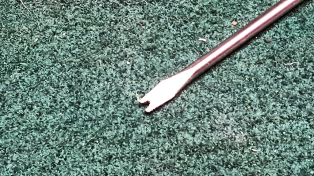
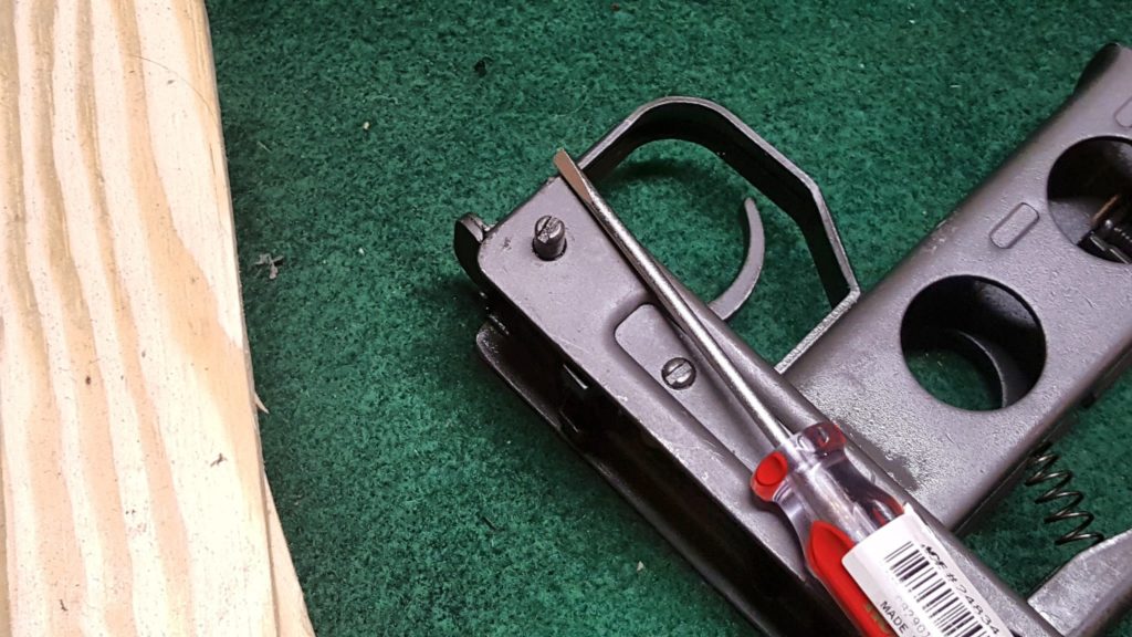
Before you get started, you need to make a quick tool. Take any small blade screw driver and use a Dremel fiber reinforced cut off wheel to make a notch in it. Literally, just cut straight in. You will need this to push down the surprisingly stout legs on the trigger spring that have to pass under some hooks and then under the disconnector.
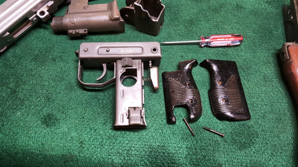
1] Remove the two screws that hold the grip panels in place. You’ll notice the grip panels are beat up but the parkerized finish and parts are in exceptional shape. All my internals looked like new. I am real pleased with the kits Robert RTG sent me.
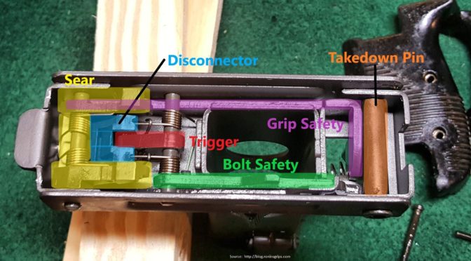
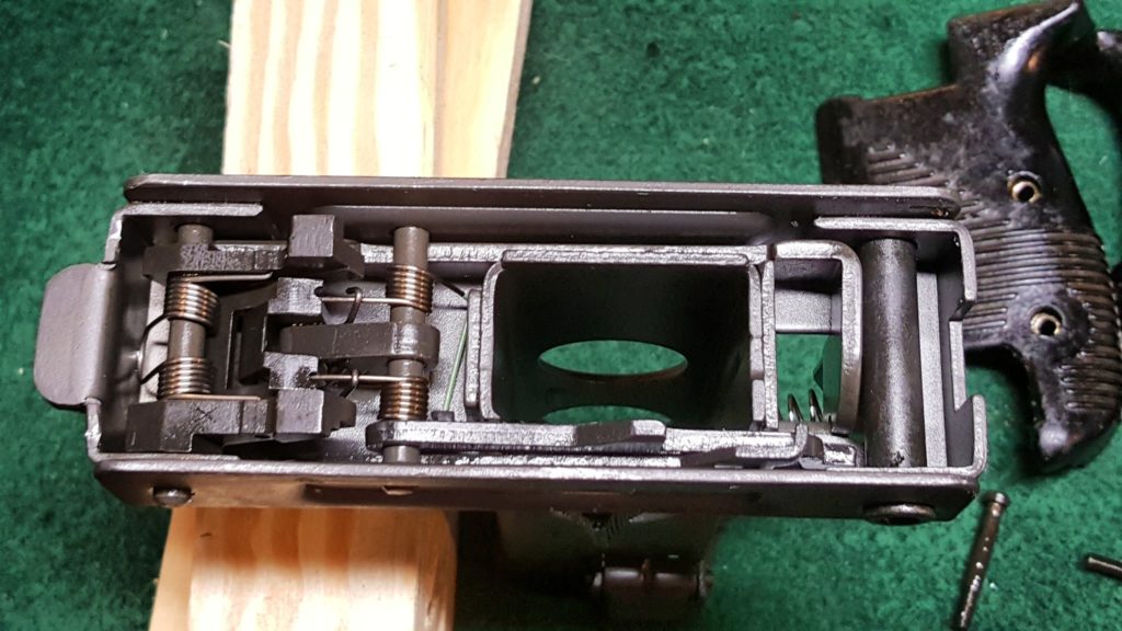
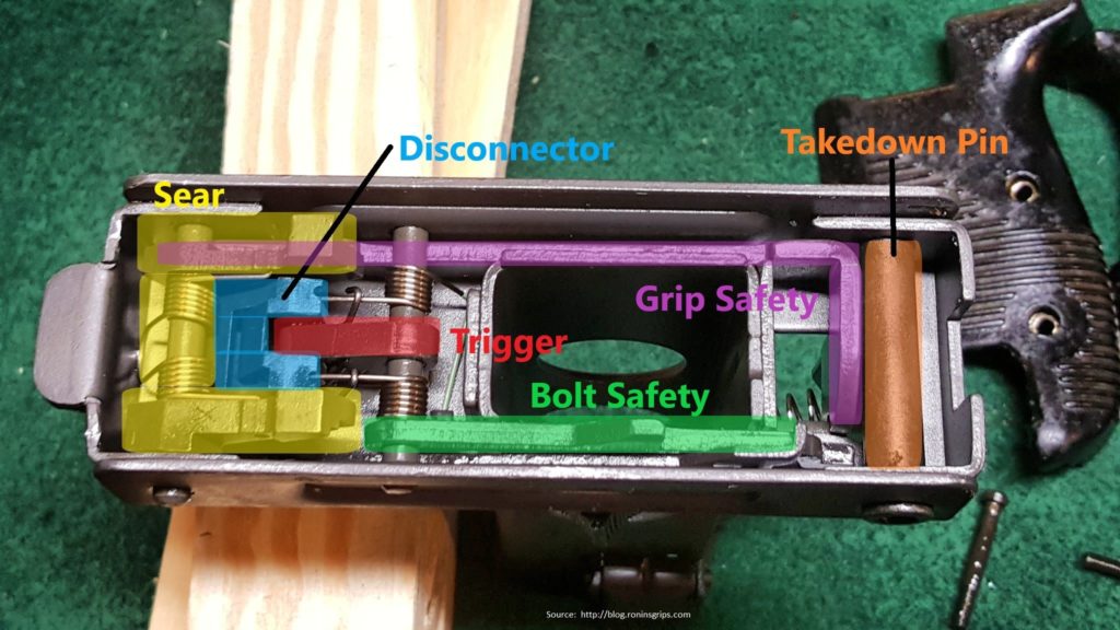
2] Here’s our first peek inside the grip frame. This crazy looking thing is actually very straight forward. I was really impressed by how they did the pins – the look like screws but you actually insert the pins and turn them into position to lock everything in place. It’s really a very well thought out way to do it.
I will never get any awards for illustration but here are the major parts labelled so you can see them. Note how the trigger pin bends forward, under the hooks and under each side of the disconnector. To remove and install the trigger requires the notched screw driver I showed above as the notch makes moving each incredibly stiff small spring leg on the trigger way, way easier.
3] Next, I pushed out the takedown pin. It just presses right out like an HK’s. I suspect that whomever demilled the kits just stuck it in there for safe keeping. Have baggies or a parts tray to keep track of all of this. I always recommend taking photos and/or making notes too.
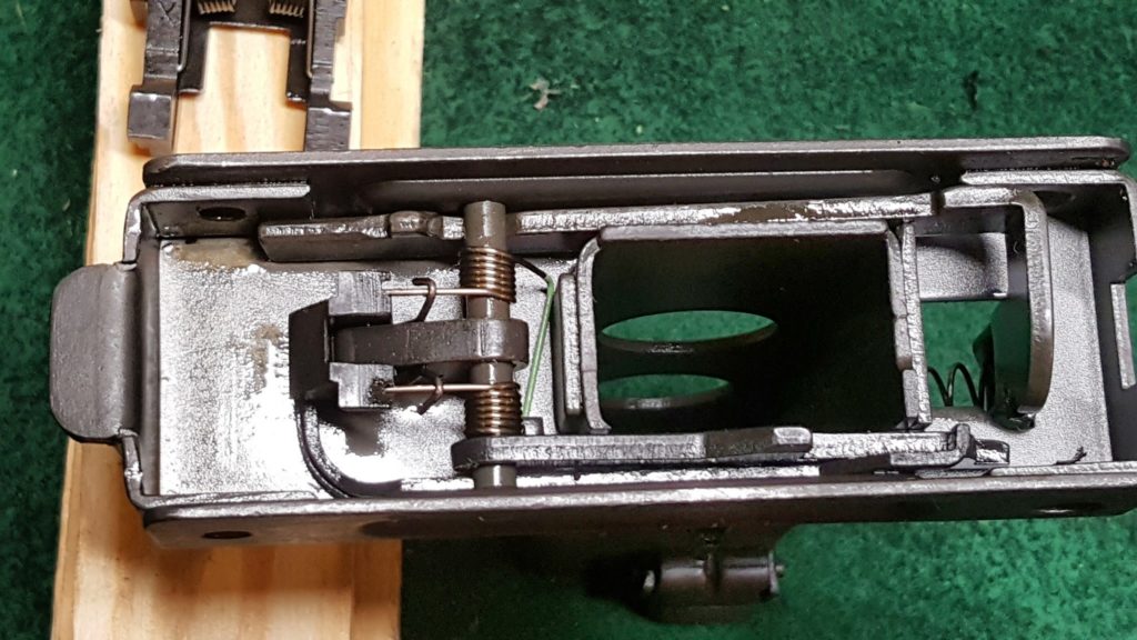
4] Before you remove the sear, look at how much room you have in front and under the sear. This will aid you when you weld in the selector stop plate later. I used a small screw driver to push out the sear pin. The spring is attached to the sear and when the pin is removed, it comes out as a unit. This unit will either need to have the lobes cut down to fit in the receiver or use a new dedicated US semi-auto sear but you will use the same spring so be sure to save it.
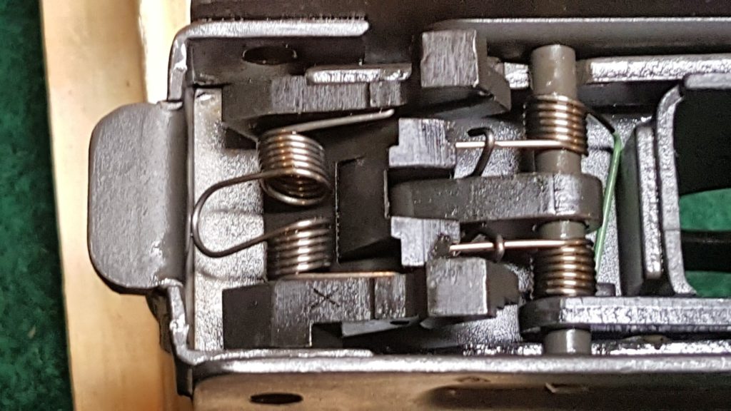
5] Next, use your tool to push down on the trigger spring legs such that they are sticking up in the air and not under the disconnector or the wire hooks.
6] Once the trigger pin is removed you can then remove all the other parts. Remove the grip safety spring and then lift the grip safety straight out of the frame.
7] Next you need to size the selector stop plate you need. In digging around, I could not find any sheet metal between .050-.075″ thick in my collection so I simply bought a pre-made selector stop plate from US Barrel Shrouds for $2.95 and made sure the selector stopped appropriately and where to place it for welding before I removed the selector bar spring and the selector bar. You want to make sure the selector fully stops on semi-auto, the middle setting, and not further to the left. You may need to adjust the plate a bit – in my case it dropped right in and worked. Also, the selector bar has virtually no vertical travel when the grip frame is fully assembled so don’t worry about that right now.
Note, the selector knob is just pressed onto the selector bar. When you remove the bar, the knob will fall off so be prepared to catch it.
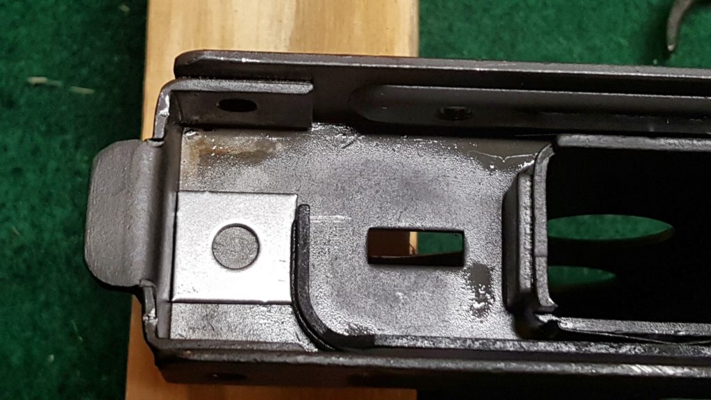
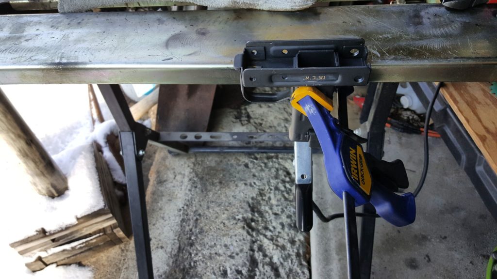
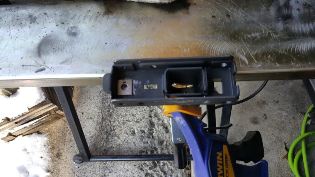
8] I then degreased and sanded the frame to remove the parkerizing in order to get a good weld. I then clamped the work and spot welded it with my MIG. You actually have a fair amount of room so the weld does not need to be perfectly flat – I did a bit more sanding than I needed to before I realized the amount of room I had to work with during test fitting. I also did two small spot welds in each corner by the lop of the frame just to be sure. My stop plate is rock solid now.
9] I did not bother removing the magazine catch and at this point, I stopped as I collected all my parts to refinish them with Molyresin. I them re-assembled following that.
10] To re-assemble the grip frame, what saved my bacon was the excellent guidance from Uzi Talk with one exception. The McKay receiver does not use a bolt safety so when the Uzi Talk directions mention it, remember that you are not going to install the bolt safety. If you do mistakenly install the bolt safety, the grip frame will not fit onto the receiver.
During assembly, I put Tetra grease on everything to help everything slide plus I oiled the rotating parts on the pins. There is an old saying “if it slides, grease it. If it rotates, oil it.”
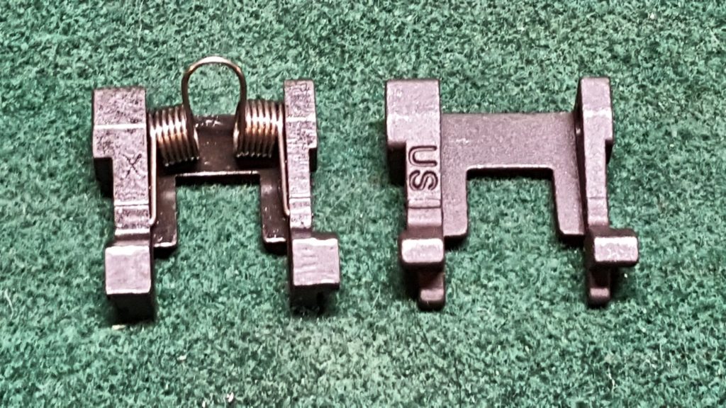
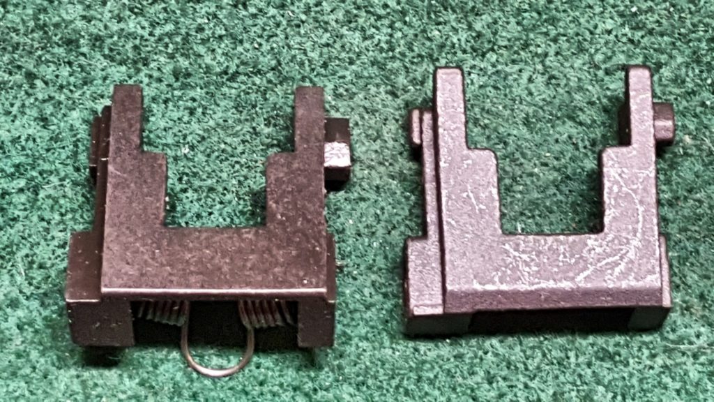
Also, I mentioned I used a US made semi-auto sear. I bought mine from US Barrel shrouds and it worked great. The original is on the left with the spring still attached. The new one is labelled US in the photos below or does not have the spring yet. I thought you might want to get a good look at it for reference. Note how the “pads” at the rear of the semi-auto sear are shorter but there is still a shelf at the bottom.
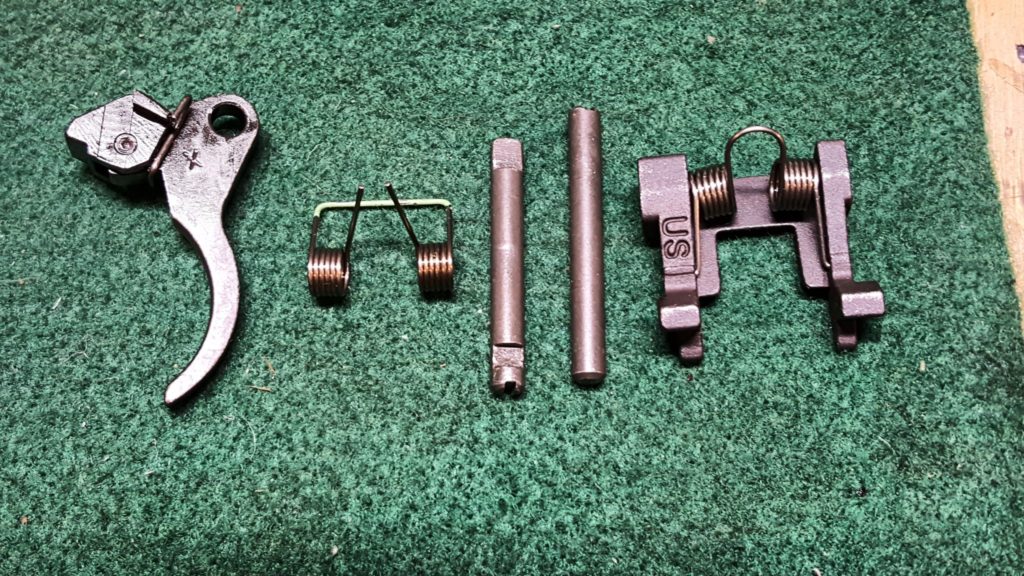
Below is a photo of the FCG group with the sear spring moved over plus it’s interesting to see the two fire control pins – the shorter one with the flat end is the trigger pin and the longer one is for the sear.
I hope this helps! Next up is the top cover assembly.
Please share the link on Facebook, Forums, with colleagues, etc. Your support is much appreciated and if you have any feedback, please email us in**@*********ps.com. If you’d like to request a report or order a reprint, please click here for the corresponding page to open in new tab.