The Uzi submachine gun is more than an iconic firearm; it is a physical embodiment of the strategic imperatives that shaped the nascent state of Israel. Born from the logistical chaos of the 1948 Arab-Israeli War, the Uzi was conceived as a definitive solution to a critical national security vulnerability: the lack of a standardized, reliable, and domestically produced personal defense weapon. Its development, spearheaded by Uziel Gal, was a masterclass in pragmatic engineering, synthesizing the most advanced design concepts of its time with the stark manufacturing realities of a new and resource-constrained nation. The Uzi’s innovative telescoping bolt and stamped-steel construction delivered a weapon that was compact, controllable, inexpensive to mass-produce, and exceptionally durable.
While its initial role was to arm the Israel Defense Forces (IDF), the Uzi’s success transcended national borders, becoming one of the most widely proliferated and recognizable submachine guns of the 20th century. Its evolution from the original model to the compact Mini and Micro variants, and ultimately to the modernized Uzi Pro, mirrors the changing doctrines of modern warfare—from conventional state-on-state conflict to the specialized demands of counter-terrorism and the contemporary emphasis on modularity and precision. However, the design was not without its inherent limitations, particularly those associated with its open-bolt operating system and the ballistic constraints of its pistol caliber chambering. Ultimately, the Uzi’s legacy is twofold: it stands as a pivotal achievement in military ordnance that served as a proof-of-concept for Israel’s formidable defense-industrial complex, and as an unexpected cultural icon whose menacing silhouette became deeply ingrained in the global consciousness.
Section 1: Genesis of a Standardized Weapon: The Post-War IDF Arsenal
1.1 The Logistical Nightmare of 1948
The Israel Defense Forces, formally established on May 26, 1948, just days after the state’s declaration of independence, entered the 1948 Arab-Israeli War with a small arms inventory that can only be described as a logistical nightmare.1 The arsenal was a dangerously heterogeneous collection of weapons procured from any and all available sources, reflecting the desperation of the pre-state Jewish paramilitary organizations (Haganah, Irgun, and Lehi) operating under the constraints of a British Mandate and a widespread arms embargo.1
This chaotic inventory included a vast array of rifles from different eras and countries of origin. The primary battle rifles were German Mauser Kar98k variants, largely supplied by Czechoslovakia, and British Lee-Enfield SMLE rifles, often stolen from British armories.4 Alongside these were American M1 Garands and M1 Carbines, and a motley assortment of other bolt-action and semi-automatic rifles.5 The situation with automatic weapons was equally dire. The IDF fielded British Sten guns, some of which were produced locally in clandestine workshops, German MP38/40s, and American Thompson and M3 “Grease Gun” submachine guns.5
This diversity created crippling challenges that threatened the operational effectiveness of the nascent Israeli army. The most pressing issue was ammunition supply. A single infantry unit could be fielding weapons chambering 7.92x57mm Mauser,.303 British, 9x19mm Parabellum, and.45 ACP, all at the same time.3 This complicated logistics to a breaking point, making resupply under combat conditions a perilous gamble. Furthermore, the lack of interchangeability meant that procuring and distributing spare parts was nearly impossible, leading to high rates of attrition for weapons that could not be repaired in the field. Finally, this “arsenal of democracy and its adversaries” made standardized training exceptionally difficult. Soldiers had to be familiarized with multiple weapon systems, each with its own manual of arms, maintenance procedures, and ballistic characteristics, reducing overall combat proficiency.7 The clear and urgent lesson of the 1948 war was that military effectiveness and, indeed, national survival, depended on the standardization of equipment.
1.2 The Strategic Imperative for Self-Sufficiency
The logistical problems of 1948 were a symptom of a much larger strategic vulnerability: a dependency on unreliable foreign arms suppliers. During the war, major powers, including the United States and Great Britain, maintained a strict arms embargo on all belligerents, severely limiting Israel’s ability to acquire modern weaponry through official channels.1 While clandestine shipments, most notably from Czechoslovakia, proved vital, Israeli leadership under David Ben-Gurion recognized that such arrangements were subject to the shifting winds of international politics and could not be relied upon for long-term security.2 The only viable path to a secure future was the development of a robust, indigenous defense industry.
The foundation for this industry had already been laid during the British Mandate. The Yishuv (the pre-state Jewish community in Palestine) had established a network of secret, underground factories to produce small arms and munitions, hiding their activities from British authorities.6 These workshops manufactured grenades, mortars, millions of rounds of ammunition, and copies of the simple British Sten gun, using surplus American machinery acquired as scrap after World War II.6
After the war, these clandestine operations were centralized and formalized under a new state-owned conglomerate: Israel Military Industries (IMI).6 IMI was tasked with a clear mission: to design and produce standardized, reliable, and effective weapons for the IDF, freeing the nation from the precariousness of foreign supply. The development of a new, domestically produced submachine gun was one of its first and most critical projects.8 This project was not merely about creating a new gun; it was a fundamental test of Israel’s new doctrine of military self-reliance. Its success would validate this strategic pivot, providing the technical expertise, industrial capacity, and national confidence needed to undertake more ambitious projects in the future, from the Galil assault rifle to the Merkava main battle tank and beyond.3 The Uzi was, in effect, the first major proof-of-concept for the entire Israeli defense-industrial complex.
Section 2: The Architect and His Influences: Uziel Gal and the Czech Connection
2.1 Profile of the Designer
The man who would answer the IDF’s call for a new submachine gun was Uziel Gal. Born Gotthard Glas in 1923 in Weimar, Germany, his early life was shaped by the turbulent rise of Nazism.11 To escape persecution, his family fled, first to the United Kingdom in 1933 and then, in 1936, to Kibbutz Yagur in British Mandate Palestine, where he adopted the Hebrew name Uziel Gal.7
From a young age, Gal displayed a remarkable aptitude for mechanics and firearms design. As a teenager, he demonstrated this innate talent by inventing and building a bow capable of firing arrows automatically—a “submachine bow,” in essence.7 This passion for weapons development found a natural home in the Palmach, the elite fighting force of the Haganah underground.14 However, his activities did not go unnoticed by the British authorities. In 1943, he was arrested for illegal possession of a firearm and sentenced to six years in prison.7 In a turn of fate, this punishment became a crucial educational opportunity. While incarcerated, Gal formally studied mechanical engineering, gaining the theoretical knowledge to complement his practical skills.13
He was released in 1946, having served less than half his sentence, and immediately resumed his work developing weapons for the Jewish forces preparing for the inevitable conflict.12 After serving as an officer in the 1948 war, Lieutenant Gal was in a unique position to understand the shortcomings of the IDF’s disparate arsenal. In 1949, he submitted a proposal in a competition for a new, domestically designed submachine gun, leveraging his intimate knowledge of both battlefield requirements and mechanical engineering.7
2.2 The Czechoslovakian Influence
Uziel Gal’s brilliance lay not in a singular moment of pure invention, but in his ability to recognize, synthesize, and pragmatically improve upon the most advanced engineering concepts of his time. The primary influence for the Uzi’s revolutionary layout came from Czechoslovakia, a nation that had become a key, albeit politically motivated, arms supplier to Israel during the 1948 war.2 This relationship gave Israeli designers, including Gal, a firsthand look at some of the most innovative post-war small arms designs.
Gal was particularly inspired by the Czech ZK 476 prototype and the subsequent production models, the Sa 23 and its variants.7 These Czech submachine guns were among the first in the world to successfully implement two groundbreaking features: a telescoping bolt and a magazine housed inside the pistol grip.13 This was a radical departure from the conventional submachine gun layout of the era, exemplified by weapons like the German MP40 and the American Thompson, which featured a magazine well located forward of the trigger group. This traditional design necessitated a longer receiver and resulted in a significantly longer and often less balanced weapon.17
Gal recognized the profound tactical advantages of the Czech configuration. By moving the magazine into the pistol grip and allowing the bolt to telescope over the barrel, a far more compact weapon could be created without sacrificing barrel length, which is crucial for maintaining adequate muzzle velocity and effective range. He took this advanced but relatively obscure European concept and systematically “Israelized” it. His contribution was to adapt the core principles to meet the specific, pressing requirements of the IDF. He simplified the design for mass production using stamped sheet metal, a necessity for Israel’s nascent industry; he engineered it for exceptional reliability in the harsh desert environment; and he integrated a multi-tiered safety system tailored to the needs of a largely conscript army. The Uzi is therefore a masterclass in adapting advanced theory to solve real-world problems, a testament to Gal’s genius for pragmatic and robust engineering synthesis.
Section 3: Engineering an Icon: A Technical Deep-Dive into the UZI’s Design
3.1 The Telescoping Bolt
The heart of the Uzi’s design, and the feature most responsible for its revolutionary compactness, is its telescoping bolt.16 In a conventional blowback submachine gun, the bolt is a solid block of steel that reciprocates entirely behind the barrel’s breech. In contrast, the Uzi’s bolt is hollowed out at its front end, allowing it to “wrap around” or telescope over the rear portion of the barrel during its cycle of operation.7
This engineering solution has several profound advantages. First and foremost, it dramatically reduces the overall length of the weapon. Because a significant portion of the barrel’s length is recessed within the bolt for most of its travel, the receiver can be made much shorter. A direct comparison to the German MP40, which uses a conventional bolt, is illustrative. The MP40 has a total length of 630 mm with its stock folded, while the Uzi measures just 470 mm—a reduction of 160 mm, or over 6 inches. Remarkably, the Uzi achieves this compactness while having a slightly longer barrel (260 mm vs. 251 mm), preserving the projectile’s muzzle velocity.17
Second, the telescoping design allows for the use of a heavier bolt in a shorter weapon. In a simple blowback action, the mass of the bolt is the primary factor that counteracts the rearward pressure of the fired cartridge, controlling the timing of the action and the cyclic rate of fire. A heavier bolt slows the cycle down. The Uzi’s heavy bolt resulted in a relatively sedate and highly controllable cyclic rate of approximately 600 rounds per minute (rpm). This slow rate of fire makes the weapon more stable in full-automatic fire, allowing for more accurate and effective short bursts, a critical feature for a military submachine gun.22 Gal’s design, inspired by the Czech Sa 23, also offset the barrel towards the bottom of the rectangular bolt, which helped to lower the axis of recoil and further mitigate muzzle rise during automatic fire.17
3.2 Manufacturing for a New Nation
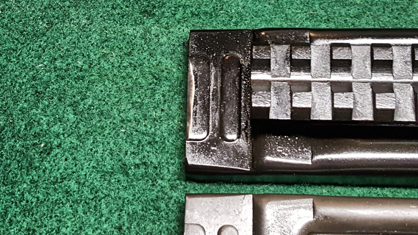
The Uzi was designed not only for combat effectiveness but also for manufacturability under the specific economic and industrial conditions of 1950s Israel. A key decision in this regard was the extensive use of stamped sheet metal for major components, particularly the receiver.16 This method was significantly cheaper, faster, and required less specialized machinery than producing parts from machined forgings, as was common in many older submachine gun designs.8 This philosophy prioritized the rapid, affordable mass production necessary to equip the entire IDF, embodying a “good enough” approach that did not sacrifice core reliability.
The design also incorporated features specifically intended to enhance reliability in the sandy, dusty conditions of the Middle East. The stamped receiver included pressed-in reinforcement slots that also served as channels to collect sand, dirt, and other debris. This allowed the weapon to continue functioning even with a significant amount of internal contamination that might jam a weapon with tighter tolerances.16 The Uzi was built with relatively few moving parts, making it simple to field strip, clean, and maintain, an important consideration for an army of conscripts.20
3.3 Ergonomics and Safety by Design
The Uzi’s design reflects a deep understanding of weapon handling under the stress of combat. The placement of the magazine well inside the pistol grip, a direct benefit of the telescoping bolt, centers the weapon’s mass directly over the firing hand. This creates a weapon with exceptional balance, making it feel more like a large pistol and allowing it to be aimed and fired accurately with one hand if necessary.22
This layout also provides a significant ergonomic advantage during reloading. The principle of “hand finds hand” means that even in complete darkness or when the operator’s attention is focused on a threat, the spare magazine can be intuitively guided into the grip without fumbling.16 This is a marked improvement over conventional designs that require the operator to locate a forward-mounted magazine well.
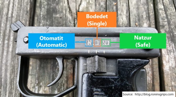
Recognizing that the Uzi would be issued to a conscript army with varying levels of firearms experience, Uziel Gal incorporated a robust, multi-layered safety system. This system included three distinct mechanisms:
- A three-position selector lever on the left side of the grip, allowing the user to choose between “S” (Safe), “R” (Repetition/Semi-Automatic), and “A” (Automatic).16
- A prominent grip safety located on the backstrap of the pistol grip. The weapon cannot be fired unless this safety is firmly depressed by the user’s hand, preventing accidental discharge if the weapon is dropped or snagged.16
- An internal bolt safety mechanism that functions as a ratchet, catching the bolt if the charging handle is released before it is fully retracted to engage the sear, preventing a slam-fire.16 This redundancy was essential for ensuring the safe handling of the open-bolt weapon by a wide range of soldiers.
3.4 The 9x19mm Chambering: A Deductive Analysis
While primary design documents are not available, a deductive analysis of the strategic and logistical context of the post-1948 IDF strongly indicates that the choice of the 9x19mm Parabellum cartridge was a deliberate and multifaceted decision.
First, it was a matter of logistical simplification. The IDF’s chaotic initial inventory already included a significant number of weapons chambered in 9mm, including the British Sten, German MP40, and various sidearms like the Browning Hi-Power.3 Furthermore, the clandestine Yishuv workshops had already established the capability to manufacture 9mm ammunition locally during the Mandate period.6 Standardizing on the 9mm caliber for the new submachine gun would therefore streamline a dangerously over-complicated supply chain and leverage existing production infrastructure.
Second, 9mm Parabellum was the global standard. By the 1950s, it had become the de facto submachine gun and pistol cartridge for most of the world’s armies.18 Choosing this caliber ensured that ammunition could be procured on the international market if necessary and, more importantly, positioned the Uzi for future export success. A weapon chambered in a ubiquitous caliber is far more attractive to foreign militaries than one requiring a proprietary or obscure ammunition type.
Finally, the cartridge offered the ideal ballistic suitability for the Uzi’s intended role and operating mechanism. The 9mm round provides a well-understood balance of terminal effectiveness in close-quarters combat, relatively low and manageable recoil, and a compact size that allows for high-capacity magazines.18 Crucially, its power level is perfectly suited for a simple, robust, and inexpensive blowback operating system. A more powerful cartridge would have necessitated a more complex and costly locked-breech or delayed-blowback mechanism, contrary to the core design goals of simplicity and economy of manufacture.
Section 4: The UZI Family: A Lineage of Adaptation and Evolution
The original Uzi was not a static design. Over more than half a century, it evolved into a diverse family of weapons, with each new variant reflecting changes in combat doctrine, technological advancements, and market demands. This evolution demonstrates a continuous effort to adapt the core design for new roles, often involving significant engineering trade-offs between size, concealability, and controllability.
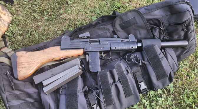
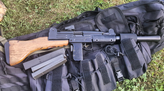
- Standard UZI (1954): The foundational design that entered service with the IDF. It operated from an open bolt with a cyclic rate of approximately 600 rpm. It was issued with either a distinctive downward-folding metal stock for compactness or a fixed wooden stock for improved stability and a better cheek weld.8 This model established the Uzi’s reputation for reliability and effectiveness in close-quarters combat.
- Mini-Uzi (1980): Developed in the late 1970s and introduced in 1980, the Mini-Uzi was a direct response to the needs of special forces, vehicle crews, and security details who required a more concealable weapon. It was a scaled-down version of the standard model, featuring a shorter barrel (197 mm), a shorter receiver, and a simpler, side-folding metal stock. To achieve this reduction in size, the bolt had to be significantly lightened. In a blowback system, a lighter bolt travels faster, and the Mini-Uzi’s rate of fire consequently skyrocketed to a blistering 950 rpm, with some tests showing it exceeding 1,300 rpm.19 This made the weapon much more difficult to control in full-auto fire, representing a clear trade-off of controllability for compactness.
- Uzi Pistol (1984): This variant was not created for a military requirement but was instead a product of market regulations. Developed specifically for the lucrative U.S. civilian market, the Uzi Pistol was a semi-automatic only version of the Micro-Uzi without a shoulder stock. Crucially, it was re-engineered to fire from a closed bolt. This change was necessary to comply with U.S. Bureau of Alcohol, Tobacco, and Firearms (ATF) regulations, which determined that semi-automatic open-bolt firearms were “readily convertible” to illegal machine guns.15
- Micro-Uzi (1986): In an interesting turn of events, the military Micro-Uzi was derived from the civilian Uzi Pistol. IMI took the semi-automatic, closed-bolt pistol design and adapted it back into a select-fire submachine gun, adding a small, side-folding stock.24 As an even more compact version, its bolt was lighter still, resulting in a phenomenal cyclic rate of fire advertised at 1,200 rpm but often testing well over 1,400 rpm.23 This extreme rate of fire made it a highly specialized weapon, suitable for VIP protection details or extreme close-quarters battle where a massive volume of fire in a fraction of a second was prioritized over sustained accuracy.
- Uzi Pro (2010): The most recent and radical evolution of the platform, the Uzi Pro is a thorough modernization of the Micro-Uzi design. It addresses many of the original’s shortcomings and brings the platform into the 21st century. The lower receiver is made from advanced polymers to reduce weight, and the magazine release was relocated to a more conventional position on the pistol grip.34 The charging handle was moved from the top of the receiver to the left side, which freed up the entire top surface for a full-length MIL-STD-1913 Picatinnym rail, allowing for the easy mounting of modern optics.34 An additional rail was added under the barrel for lights and lasers. Most significantly, the select-fire Uzi Pro SMG fires from a
closed bolt, a fundamental departure from the original design. This change dramatically improves first-shot accuracy, reflecting the modern doctrinal emphasis on precision over indiscriminate volume of fire.34
The Uzi’s lineage is a clear reflection of modern military history. It began as a simple, robust tool for conventional infantry warfare. It was then adapted for the rise of specialized counter-terrorism and special operations units that valued concealability above all else. Finally, it was transformed into the Uzi Pro, a modular, precision-oriented platform aligned with the doctrines of the modern, optics-equipped soldier.
Table 1: UZI Variant Technical Specifications
| Variant | Year Introduced | Caliber | Operating System | Rate of Fire (rpm) | Weight (Unloaded) | Length (Extended/Collapsed) | Barrel Length | Muzzle Velocity | Effective Range |
| Uzi SMG | 1954 | 9x19mm | Open-Bolt, Blowback | ~600 | 3.5 kg | 640 mm / 470 mm | 260 mm | 400 m/s | ~200 m |
| Mini-Uzi | 1980 | 9x19mm | Open-Bolt, Blowback | ~950 | 2.65 kg | 600 mm / 360 mm | 197 mm | 375 m/s | ~100 m |
| Micro-Uzi | 1986 | 9x19mm | Open-Bolt, Blowback | ~1250 | 2.5 kg | 486 mm / 282 mm | 117 mm | 350 m/s | ~50 m |
| Uzi Pistol | 1984 | 9x19mm | Closed-Bolt, Blowback | Semi-Auto Only | 1.66 kg | 241 mm (N/A) | 115 mm | 345 m/s | ~50 m |
| Uzi Pro SMG | 2010 | 9x19mm | Closed-Bolt, Blowback | ~1050 | 2.32 kg | 529 mm / 300 mm | 152 mm | 380 m/s | ~100 m |
Section 5: A Critical Assessment: Inherent Shortcomings of the UZI Design
Despite its success and iconic status, the original Uzi design and its direct descendants were not without significant engineering and tactical shortcomings, primarily stemming from their open-bolt operating system and the inherent limitations of the pistol cartridge they fired.
5.1 The Open-Bolt Conundrum
The Uzi’s simple, open-bolt blowback mechanism was key to its reliability and low cost, but it also introduced a set of unavoidable disadvantages that were well-understood by firearms engineers.41
- First-Shot Accuracy: The most significant tactical drawback of an open-bolt system is its negative impact on first-shot accuracy. When the trigger is pulled, it does not release a hammer or striker; it releases the entire heavy bolt assembly, which then slams forward under spring pressure. This large mass moving within the weapon before the round is even chambered and fired introduces significant disturbance to the shooter’s point of aim.42 This “ka-chunk” effect makes the precise placement of the first shot—often the most critical in an engagement—far more difficult than with a closed-bolt weapon like the Heckler & Koch MP5, where the only major mechanical action upon pulling the trigger is the fall of a small hammer.
- Safety Vulnerabilities: Open-bolt weapons are inherently less safe than their closed-bolt counterparts, particularly concerning drop safety. If an open-bolt weapon is cocked (bolt held to the rear) and dropped on a hard surface, the inertia of the impact can be enough to jolt the bolt off its sear engagement. The bolt will then fly forward, strip a round from the magazine, chamber it, and fire, all without the trigger being pulled.41 While the Uzi’s grip safety was designed to mitigate this, the fundamental vulnerability remains a characteristic of the operating system.
- Environmental Susceptibility: When an open-bolt weapon is cocked and ready to fire, the ejection port is wide open, exposing the internal action directly to the elements. This creates a large ingress point for sand, dust, mud, and other battlefield debris, which can accumulate in the receiver and cause malfunctions.16 While the Uzi’s design included features to tolerate some debris, this vulnerability was a persistent concern, especially in the desert environments where the IDF primarily operated.
5.2 The Limits of a Pistol Caliber Platform
The second major limitation of the Uzi was not a flaw in its design, but rather an inherent constraint of its chambering. The 9x19mm Parabellum is a pistol cartridge, designed for engagements at close range. While effective in its intended role of clearing trenches, buildings, or for personal defense by vehicle crews, its performance drops off rapidly at extended distances.18
The Uzi’s maximum effective range is generally cited as 200 meters, but this is an optimistic figure achievable only under ideal conditions in semi-automatic fire.22 In practical combat, especially when firing automatically, its effective range was closer to 50-100 meters.31 This became a critical tactical disadvantage as Israel’s adversaries increasingly armed their infantry with intermediate-caliber assault rifles, most notably the Soviet AK-47 and its derivatives. These rifles fired a 7.62x39mm cartridge that was significantly more powerful and could effectively engage targets out to 300-400 meters.22 An Israeli soldier armed with an Uzi was therefore out-ranged and out-gunned by an adversary with a standard-issue assault rifle. This firepower disparity was a primary driver for the IDF’s decision to relegate the Uzi to rear-echelon and specialist roles, adopting more powerful 7.62x51mm battle rifles like the FN FAL and later, 5.56x45mm assault rifles like the Galil and M16, for its frontline infantry units.
5.3 Weight, Construction, and Ergonomics
While innovative, the Uzi’s design choices created a distinct set of physical and handling drawbacks. The weapon is notably heavy for its class; a loaded standard Uzi can weigh nearly 4 kg (9 pounds), comparable to older WWII-era submachine guns like the American M3 “Grease Gun”.18 This substantial weight, a consequence of its all-steel construction and heavy bolt, could lead to operator fatigue and made it difficult to maintain a stable hold, particularly during extended use.50
The reliance on stamped sheet metal for the receiver, while crucial for rapid and inexpensive production, had its own set of issues. Stamped receivers require a precise and repeatable heat-treatment process to ensure durability; improper execution can lead to warping or the development of micro-fractures under the stress of repeated firing.51 While original IMI-produced Uzis were generally robust, some later commercial copies were noted for poor metallurgy and finish.53 Furthermore, the most common point of failure was not the gun itself but its magazines. The sheet metal feed lips of the magazine were vulnerable to damage, and a bent feed lip was a frequent cause of feeding malfunctions.54
Ergonomically, the Uzi was often described as crude or “clunky” compared to more refined designs like the MP5.25 Criticisms focused on the stiff grip safety, an uncomfortable 90-degree grip angle, and a rudimentary folding metal stock that was functional but not comfortable for the shooter.50 A significant tactical drawback was that the long, vertically protruding magazine made the weapon awkward to fire from a prone position.16
Section 6: From the Sinai to Hollywood: The UZI’s Operational History and Legacy
The Uzi’s story extends far beyond its technical specifications. It is a weapon forged in conflict, proven on the battlefield, and unexpectedly elevated to the status of a global cultural symbol. Its historical timeline charts the course of a new nation’s struggle for survival and the evolution of modern warfare.
Table 2: Historical Timeline of the UZI
| Date / Year | Event | Significance / Note |
| 1948 | 1948 Arab-Israeli War; State of Israel and IDF founded. | Exposed the critical need for a standardized, domestically produced SMG.1 |
| 1949 | IDF initiates competition for a new submachine gun. | Uziel Gal submits his design, competing against other proposals.7 |
| 1950 | Uziel Gal’s prototype is completed. | The core design, influenced by Czech models, is finalized for testing.16 |
| 1951 | The Uzi is officially adopted by the IDF. | The design is selected over competitors for its simplicity, cost-effectiveness, and reliability.8 |
| 1952 | Uziel Gal patents his design. | Formalizes the intellectual property of the weapon’s innovative features.15 |
| 1954 | First production Uzis issued to IDF special forces. | The weapon begins its operational service with elite units.8 |
| 1956 | First major combat use during the Suez Crisis. | Proved its effectiveness in close-quarters combat, particularly in clearing Egyptian positions in the Sinai.15 |
| 1959 | West Germany adopts the Uzi as the MP2. | Marks the beginning of the Uzi’s major international export success.8 |
| 1967 | Six-Day War. | The Uzi is used extensively by Israeli forces in various roles.8 |
| 1973 | Yom Kippur War. | The Uzi continues to serve as a standard-issue SMG with the IDF.8 |
| 1980 | Mini-Uzi and semi-automatic Uzi Carbine are introduced. | The family expands to meet special forces needs and tap into the U.S. civilian market.15 |
| 1981 | U.S. Secret Service agent deploys an Uzi during the assassination attempt on President Ronald Reagan. | An iconic photograph captures the moment, cementing the Uzi’s image in the public consciousness.8 |
| 1986 | Micro-Uzi is introduced. | An even more compact variant is developed for extreme concealability and VIP protection roles.15 |
| 2003 | The Uzi is officially retired from service with the IDF. | After nearly 50 years, the weapon is phased out in favor of more modern assault rifles and carbines like the Tavor.13 |
| 2010 | The IWI Uzi Pro is introduced. | A radically modernized version with a closed-bolt action and polymer components is launched to keep the platform relevant in the 21st century.19 |
6.1 Combat Record and Global Proliferation
The Uzi’s baptism by fire occurred during the 1956 Suez Crisis. Israeli paratroopers clearing Egyptian positions, particularly in caves and trenches in the Mitla Pass, found the weapon’s compactness and controllable automatic fire to be ideal for such close-quarters engagements.15 It went on to see widespread service in every major Israeli conflict for the next three decades, including the Six-Day War of 1967 and the Yom Kippur War of 1973, arming not just infantry but also vehicle crews, artillerymen, and officers.8
The Uzi’s battlefield reputation, combined with its low cost and reliability, made it a phenomenal export success. From the 1960s through the 1980s, it was arguably the most widely sold submachine gun in the world.16 It was adopted by the militaries and law enforcement agencies of over 90 countries.19 Notable users included West Germany, which adopted it as the MP2 in 1959 to equip its tank crews and other units, the Netherlands, and Belgium, where it was license-produced by FN Herstal.8 In the United States, it gained prominence as the standard submachine gun of the Secret Service from the 1960s until the early 1990s, chosen for its concealability and volume of fire.16
The following table summarizes some of the key export and production arrangements that contributed to the Uzi’s global proliferation.
Table 3: Selected UZI Export and Production History
| Date | Country | Volume | Model(s) | Acquisition Type |
| 1956 | Netherlands | Unknown | Standard Uzi (wood & folding stock) | Direct Sale 16 |
| 1958 | Belgium | Unknown | Standard Uzi | Licensed Production (FN Herstal) 16 |
| 1959 | West Germany | 116,000+ | MP2 (wood stock), MP2A1 (folding stock) | Direct Sale 16 |
| 1960s | United States | Unknown | Standard Uzi | Direct Sale (Secret Service) 16 |
| 1976 | Rhodesia | Unknown | Standard Uzi | Licensed Production 16 |
| 1980s | South Africa | Unknown | Standard Uzi | Licensed Production 19 |
| 1990s | Sri Lanka | “Few thousand” | Mini Uzi, Uzi Carbine | Direct Sale 16 |
| 1991 | Myanmar | Unknown | BA93, BA94 | Licensed Production 16 |
| – | Croatia | Unknown | ERO, Mini ERO | Unlicensed Copy 16 |
| – | China | Unknown | Norinco M320 | Unlicensed Copy 16 |
6.2 The UZI as a Cultural Icon
While the Uzi was being gradually phased out of frontline military service by the 1980s in favor of more capable assault rifles, its presence in global popular culture was exploding. Its unique and menacing profile made it a visual shorthand for modern firepower, and it became a staple in Hollywood action films and television shows, wielded by heroes and villains alike.15
This cultural status was cemented on March 30, 1981. In the chaotic moments following the assassination attempt on U.S. President Ronald Reagan, Associated Press photographer Ron Edmonds captured a stunning image of Secret Service Special Agent Robert Wanko pulling a full-sized Uzi from a concealed briefcase to cover the presidential limousine’s escape.8 That single photograph, broadcast around the world, instantly made the Uzi one of the most recognizable firearms on the planet and inextricably linked it with elite security and covert operations.8
This media exposure created a powerful and enduring brand identity that has far outstripped and outlasted the weapon’s military relevance. While its tactical heyday had passed by the time it became a Hollywood star, its visual identity projected an image of Israeli toughness, efficiency, and cutting-edge design. This “soft power” effect created a global perception of Israeli weapons as being innovative and “battle-proven.” This perception arguably created a more receptive international market for subsequent, more advanced Israeli defense exports, from the Galil rifle to the Tavor and sophisticated missile systems like the Iron Dome. It is a clear demonstration that a weapon’s cultural impact can have tangible geopolitical and economic ripple effects long after its military utility has waned.
Conclusion
The Uzi submachine gun stands as a landmark achievement in the history of 20th-century small arms. It was a weapon that perfectly solved the specific, existential problems of its time and place: a simple, inexpensive, and utterly reliable submachine gun for a new nation fighting for its survival with a conscript army and a nascent industrial base. Its design was not a work of radical invention but rather a masterwork of pragmatic adaptation. Uziel Gal brilliantly synthesized the most advanced submachine gun concepts of the post-war era, refining them into a platform optimized for mass production and battlefield durability.
The weapon’s subsequent evolution from the standard model to its more compact and specialized variants is a direct reflection of the changing face of modern warfare, from the conventional battlefields of the Sinai to the close-quarters demands of global counter-terrorism. Its eventual replacement in frontline IDF service was not a sign of failure, but rather a testament to its success in helping secure a nation that could then afford and doctrinally require more advanced, longer-ranged infantry weapons.
Ultimately, the Uzi leaves a dual legacy. As a piece of military engineering, it was a pivotal success that validated Israel’s strategic doctrine of self-reliance and served as a cornerstone for its world-class defense industry. As a cultural object, it acquired a life of its own, its unmistakable silhouette becoming a global symbol of lethality and modern conflict. It remains a rare example of a weapon that is as significant for its engineering solutions as it is for its enduring, and often notorious, place in the public imagination.
Please share the link on Facebook, Forums, with colleagues, etc. Your support is much appreciated and if you have any feedback, please email us in**@*********ps.com. If you’d like to request a report or order a reprint, please click here for the corresponding page to open in new tab.
Sources Used
- Milestones: The Arab-Israeli War of 1948 – Office of the Historian, accessed September 11, 2025, https://history.state.gov/milestones/1945-1952/arab-israeli-war
- 1948 Arab–Israeli War – Wikipedia, accessed September 11, 2025, https://en.wikipedia.org/wiki/1948_Arab%E2%80%93Israeli_War
- List of equipment of the Israel Defense Forces – Wikipedia, accessed September 11, 2025, https://en.wikipedia.org/wiki/List_of_equipment_of_the_Israel_Defense_Forces
- During the 1948 war, what was the primary rifle of the IDF and the Zionist militias that immediately preceded it? : r/Israel – Reddit, accessed September 11, 2025, https://www.reddit.com/r/Israel/comments/kq4z1e/during_the_1948_war_what_was_the_primary_rifle_of/
- What weapons did the Jewish militias in Israel use pre-1948? – Quora, accessed September 11, 2025, https://www.quora.com/What-weapons-did-the-Jewish-militias-in-Israel-use-pre-1948
- Defense industry of Israel – Wikipedia, accessed September 11, 2025, https://en.wikipedia.org/wiki/Defense_industry_of_Israel
- Man with the Mark of the Submachine Gun | RANGER PRAGUE, accessed September 11, 2025, https://www.pragueranger.cz/blog/man-with-the-mark-of-the-submachine-gun/
- History of the Uzi – McCluskey Arms, accessed September 11, 2025, https://mccluskeyarms.com/gunsmithing-blog/history-of-the-uzi
- en.wikipedia.org, accessed September 11, 2025, https://en.wikipedia.org/wiki/Uzi#:~:text=The%20Uzi%20submachine%20gun%20was,simplicity%20and%20economy%20of%20manufacture.
- Full article: Israel’s defence industry: adaptation and growth in a changing arms market, accessed September 11, 2025, https://www.tandfonline.com/doi/full/10.1080/14702436.2025.2472720
- Uziel Gal – Wikipedia, accessed September 11, 2025, https://en.wikipedia.org/wiki/Uziel_Gal
- Uziel Gal – Jewish Virtual Library, accessed September 11, 2025, https://www.jewishvirtuallibrary.org/uziel-gal
- Uziel Gal | Israeli Army Officer, Gun Designer & Engineer | Britannica, accessed September 11, 2025, https://www.britannica.com/biography/Uziel-Gal
- How a Kid Who Liked to Saw Rifles Became the Inventor of the Uzi, accessed September 11, 2025, https://blog.nli.org.il/en/uzi/
- The Ubiquitous Uzi | Rock Island Auction, accessed September 11, 2025, https://www.rockislandauction.com/riac-blog/the-uzi
- Uzi – Wikipedia, accessed September 11, 2025, https://en.wikipedia.org/wiki/Uzi
- Telescoping bolt – Wikipedia, accessed September 11, 2025, https://en.wikipedia.org/wiki/Telescoping_bolt
- Uzi submachine gun | Israeli, Compact, Automatic – Britannica, accessed September 11, 2025, https://www.britannica.com/technology/Uzi-submachine-gun
- IMI Uzi | Weaponsystems.net, accessed September 11, 2025, https://weaponsystems.net/system/237-IMI+Uzi
- The Uzi – Owen Guns, accessed September 11, 2025, https://owenguns.com/blogs/museum-weapons/the-uzi
- Uzi submachine gun – CAT-UXO, accessed September 11, 2025, https://cat-uxo.com/explosive-hazards/salw/uzi-submachine-gun
- Israel’s Uzi Submachine Gun: The Story of an Iconic Weapon – The …, accessed September 11, 2025, https://nationalinterest.org/blog/reboot/israels-uzi-submachine-gun-story-iconic-weapon-168589
- Development of the Uzi Family: Standard, Mini, and Micro – YouTube, accessed September 11, 2025, https://www.youtube.com/watch?v=t-iuZyNJYyo
- Development of the Uzi Family: Standard, Mini, and Micro – Forgotten Weapons, accessed September 11, 2025, https://www.forgottenweapons.com/development-of-the-uzi-family-standard-mini-and-micro/
- Uzi Insanity: Meet the Feared Israeli Submachine Gun – Guns.com, accessed September 11, 2025, https://www.guns.com/news/reviews/uzi-insanity-meet-the-feared-israeli-submachine-gun
- How a UZI Works – YouTube, accessed September 11, 2025, https://www.youtube.com/watch?v=OmbJhU1pjFk
- Submachine gun – Wikipedia, accessed September 11, 2025, https://en.wikipedia.org/wiki/Submachine_gun
- Uzi (& later variants) Technical Information Variants and their …, accessed September 11, 2025, https://www.smallarmssurvey.org/sites/default/files/SAS_weapons-sub-machine-guns-Uzi.pdf
- Uzi – Wikipedia, accessed September 11, 2025, https://sco.wikipedia.org/wiki/Uzi
- How fast does an Uzi shoot? – Quora, accessed September 11, 2025, https://www.quora.com/How-fast-does-an-Uzi-shoot
- The Uzi, why it resides in our in-house arsenal – SilencerCo Blog, accessed September 11, 2025, https://silencerco.com/blog/arsenal-blog-002-uzi/
- The Micro UZI – The Armourers Bench, accessed September 11, 2025, https://armourersbench.com/2018/04/23/the-micro-uzi/
- The DIY Uzi 9mm: a guide to legally and easily building your own : r/guns – Reddit, accessed September 11, 2025, https://www.reddit.com/r/guns/comments/ljmguw/the_diy_uzi_9mm_a_guide_to_legally_and_easily/
- UZI Submachine Gun | IWI UZI PRO, accessed September 11, 2025, https://iwi.net/uzi-submachine-gun/
- IWI Pistol, Model : UZI PRO, Barrel Length : 4.5 inches, Caliber :. 9x19mm – TargetZone.eu, accessed September 11, 2025, https://targetzone.eu/pistolet-iwi-uzi-pro-4-5inch-kal-9x19mm.html
- UZI Pro – Modern Micro Semi-Auto 9mm Pistol | IWI US, accessed September 11, 2025, https://iwi.us/firearms/uzi-pro/
- UZI PRO – Micro Semi-Auto Pistol with Threaded Barrel | IWI US, accessed September 11, 2025, https://iwi.us/firearms/uzi-pro/uzi-pro-pistol-with-threaded-barrel/
- UZI PRO SMG (Sub Machine Gun) 9mm – Parnisari Arms, accessed September 11, 2025, https://parnisariarms.com/userdata/cataloghi/IWI-ISRAELI%20WEAPON%20INDUSTRIES/IWI_UZI_PRO_SMG.pdf
- Development of The Uzi Machine Gun | PDF | Firearms | Projectile Weapons – Scribd, accessed September 11, 2025, https://www.scribd.com/document/186249391/Development-of-the-Uzi-Machine-Gun
- UZI Submachine Gun | IWI UZI PRO, accessed September 11, 2025, https://iwi.net/uzi-submachine-gun/uzi-pro/
- Open bolt – Wikipedia, accessed September 11, 2025, https://en.wikipedia.org/wiki/Open_bolt
- Open Bolt Vs Closed Bolt Firearms – Abbey Supply, accessed September 11, 2025, https://www.abbeysupply.com/resources/open-bolt-vs-closed-bolt-firearms
- Why does an open bolt (generally) ensure less accuracy, but higher rate of fire? : r/guns, accessed September 11, 2025, https://www.reddit.com/r/guns/comments/qdm79l/why_does_an_open_bolt_generally_ensure_less/
- What exactly is the difference between an open bolt and a closed bolt? : r/guns – Reddit, accessed September 11, 2025, https://www.reddit.com/r/guns/comments/2cy57h/what_exactly_is_the_difference_between_an_open/
- Uzi – Simple English Wikipedia, the free encyclopedia, accessed September 11, 2025, https://simple.wikipedia.org/wiki/Uzi
- UZI shooting in Prague, accessed September 11, 2025, https://www.pragueranger.cz/guns/uzi/
- Firearms Legend: The Uzi Submachine Gun Can Fire 600 Rounds Per Minute – 19FortyFive, accessed September 11, 2025, https://www.19fortyfive.com/2022/04/firearms-legend-the-uzi-submachine-gun-can-fire-600-rounds-per-minute/
- How Accurate is Uzi and Similar Automatic Small Arms IRL? : r/answers – Reddit, accessed September 11, 2025, https://www.reddit.com/r/answers/comments/1khevwa/how_accurate_is_uzi_and_similar_automatic_small/
- How the Uzi Submachine Gun Earned Its Place in History – The National Interest, accessed September 11, 2025, https://nationalinterest.org/blog/reboot/how-uzi-submachine-gun-earned-its-place-history-190040
- IMI UZI Review – The Range of Richfield, accessed September 11, 2025, https://therangewi.com/imi-uzi-review/
- An Essential Uzi Guide | An Official Journal Of The NRA – American Rifleman, accessed September 11, 2025, https://www.americanrifleman.org/content/an-essential-uzi-guide/
- Can someone explain “milled” and “stamped” receivers please? : r/guns – Reddit, accessed September 11, 2025, https://www.reddit.com/r/guns/comments/gmvji/can_someone_explain_milled_and_stamped_receivers/
- The Uzi SMG Conversions – Small Arms Review, accessed September 11, 2025, https://smallarmsreview.com/the-uzi-smg-conversions/
- Are Uzi sub-machine guns reliable? – Quora, accessed September 11, 2025, https://www.quora.com/Are-Uzi-sub-machine-guns-reliable
- The Uzi Submachine Gun: Excellent or Overrated? – YouTube, accessed September 11, 2025, https://www.youtube.com/watch?v=MTL8-cVoP64
- Las Vegas Gun Range Firearms Spotlight: UZI, accessed September 11, 2025, https://machinegunexperience.com/las-vegas-gun-range-firearms-spotlight-uzi/
- Action Arms Semiauto Uzi Carbines (Model A and Model B) – Forgotten Weapons, accessed September 11, 2025, https://www.forgottenweapons.com/action-arms-semiauto-uzi-carbines-model-a-and-model-b/
- Tag: Uzi – The Armourers Bench, accessed September 11, 2025, https://armourersbench.com/tag/uzi/
- Weapon of Service: The UZI Submachine Gun in Germany – Small Arms Review, accessed September 11, 2025, https://smallarmsreview.com/weapon-of-service-the-uzi-submachine-gun-in-germany/