Category Archives: Small Arms Design & Manufacturing Analytics

Advanced Manufacturing Architectures in the Small Arms and Tactical Accessories Sector

1. Executive Summary and Macro-Industrial Context

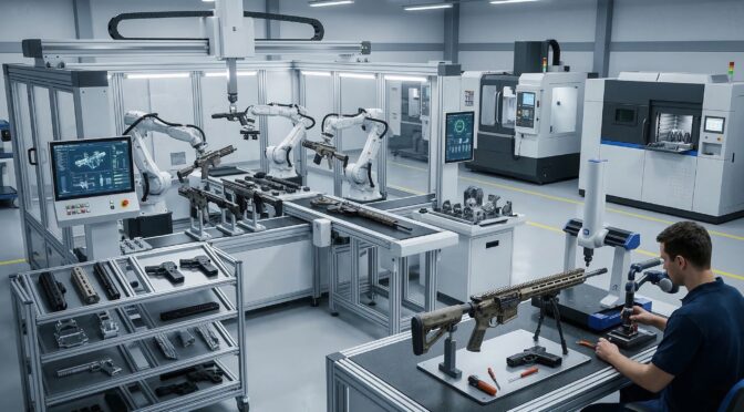
The small arms and tactical accessories manufacturing sector in 2025 and 2026 is undergoing an unprecedented paradigm shift, driven by the aggressive convergence of simultaneous 5-axis Computer Numerical Control (CNC) machining, sub-micron 3D scanning metrology, and advanced parametric reverse engineering workflows.1 Historically, the production of mission-critical defense components was dominated by tier-one defense contractors possessing massive capital expenditure capabilities and sprawling, highly sequential production lines. However, the contemporary landscape is experiencing a profound democratization of high-precision manufacturing.3 Small-to-Medium Enterprises (SMEs), particularly those clustered within advanced manufacturing hubs such as Michigan’s “Automation Alley,” are aggressively leveraging these highly automated, interconnected technologies to secure, execute, and scale critical defense contracts.5

This comprehensive technical analysis examines the transformative impact of these specific advanced manufacturing technologies on the defense supply chain. The integration of continuous 5-axis kinematics has completely redefined baseline operational efficiency within the sector. Most notably, this technology has facilitated the compression of traditional, highly fragmented multi-step manufacturing sequences into consolidated, two-operation workflows.7 This consolidation drastically lowers prototyping costs, accelerates time-to-market, and virtually eliminates the insidious issue of tolerance stacking that plagues sequential machining methodologies.7 Concurrently, the proliferation of high-resolution 3D metrology hardware and AI-assisted parametric reverse engineering software has unlocked previously impossible capabilities in ergonomic customization, component modernization, and the sustainment of legacy military platforms.10

Furthermore, a fundamental and permanent transition in materials science is occurring directly on the factory floor. To meet the stringent demands of modern combat environments, which dictate extreme weight reduction, thermal management, and structural rigidity, the industry is rapidly adopting high-performance, aerospace-grade aluminum alloys, specifically the 7075-T6 specification.13 This transition is occurring alongside the integration of advanced heat-resistant engineered thermoplastics, such as Polyetheretherketone (PEEK) and its highly abrasive glass-filled variants (PEEK-GF30).15 Processing these disparate materials necessitates entirely new, divergent machining philosophies, emphasizing strict heat control, ultra-rigid fixturing, optimized chip evacuation, and specialized Polycrystalline Diamond (PCD) tooling.17 By analyzing the intricate technical metrics, complex toolpath strategies, machine kinematics, and material behaviors associated with these technologies, this report provides an exhaustive, peer-level blueprint of the modern small arms manufacturing ecosystem.

2. Kinematics, Dynamics, and the 5-Axis Machining Revolution

2.1. The Shift from Sequential to Simultaneous Multi-Axis Machining

The foundational technology driving the current revolution in tactical accessory production is the 5-axis CNC machining center. To understand the magnitude of this shift, one must analyze the kinematic limitations of legacy systems. Traditional 3-axis machines dictate that a cutting tool moves exclusively along three linear planes: the X-axis (left-to-right), the Y-axis (front-to-back), and the Z-axis (up-and-down).18 Consequently, the cutting tool remains perpendicular to the workpiece at all times. A 5-axis machining center, however, introduces two additional rotational axes. Depending on the specific machine architecture, such as a trunnion table configuration (table/table) or a swivel-head configuration (head/head), these rotational axes are typically designated as the A-axis (rotating around the X-axis), the B-axis (rotating around the Y-axis), and the C-axis (rotating around the Z-axis).18

It is absolutely critical to distinguish between 3+2 positional machining and full, simultaneous 5-axis contouring. In 3+2 machining, also known as positional 5-axis machining, the rotational axes are utilized solely to orient the workpiece to a fixed, static position.7 Once locked into place, standard 3-axis milling programs execute the material removal. While this significantly reduces the need for manual refixturing by an operator, it is fundamentally incapable of producing the complex, sweeping organic contours required by modern aerodynamic ballistics or ergonomic tactical components.7

Full simultaneous 5-axis machining, conversely, engages all five axes (three linear, two rotational) concurrently and dynamically.9 The orientation of the cutting tool changes continuously relative to the workpiece throughout the execution of the toolpath.20 This capability allows programmers to utilize significantly shorter, more rigid cutting tools because the tool holder can tilt away from deep cavity walls, avoiding collisions.9 The employment of shorter tools dramatically reduces tool deflection and eliminates harmonic vibration (chatter) during high-speed cutting.22 Consequently, manufacturers achieve superior surface finishes that often eliminate the need for secondary hand-polishing operations, while simultaneously holding dimensional tolerances as tight as ±0.0025mm to ±0.005mm under standardized operations.7

In the context of small arms manufacturing, this continuous kinematic freedom translates directly to the production of monolithic components. Parts that previously required the complex welding, brazing, or mechanical fastening of multiple disparate sub-assemblies can now be carved efficiently from a single solid billet of material.7 This “done-in-one” approach fundamentally eliminates the structural vulnerabilities, stress risers, and failure points inherently associated with mechanical joints and welded seams, significantly enhancing the reliability of firearms subjected to extreme ballistic pressures, thermal shock, and environmental degradation.7

2.2. Machine Architecture and Metrological Stability

The execution of these complex simultaneous movements requires extraordinary mechanical rigidity and metrological stability within the machine tool itself. High-end 5-axis centers, such as those manufactured by Hermle or the GROB Systems G550 universal machining center, are engineered to mitigate the specific challenges introduced by multi-axis motion.23

Key architectural considerations include static rigidity, which dictates the machine’s resistance to deflection under heavy cutting forces, and dynamic stability, which ensures accuracy during rapid, multi-axis accelerations and decelerations.25 Furthermore, thermal stability is a critical metric. As spindles spin at excess of 20,000 RPM and linear drives rapidly actuate, the machine structure absorbs heat, leading to microscopic dimensional drift.25 Modern 5-axis machines employ temperature-controlled structures, chilled ball screws, and advanced vibration damping casting materials (such as polymer concrete or epoxy granite) to maintain absolute precision over extended “lights-out” production runs.25 Backlash, the slight mechanical play or slack in a drive system when reversing direction, is virtually eliminated through the use of high-efficiency, pre-loaded ball screws manufactured from high-performance alloy steels.27

Machining MetricTraditional 3-Axis CapabilitySimultaneous 5-Axis CapabilityOperational Impact on Defense Manufacturing
Kinematic MotionLinear X, Y, Z only. Tool remains perpendicular to part.Concurrent X, Y, Z, A, B/C motion. Tool orientation adapts dynamically.Enables machining of undercuts, complex organic surfaces, and deep internal cavities without collision.
Setup RequirementsRequires up to 9 manual refixturing operations for complex parts.Minimum 1 to 2 setups utilizing dovetail workholding.Drastically reduces machine downtime, labor costs, and cumulative tolerance stacking errors.
Tooling RigidityOften requires long reach tools to access deep features, causing deflection.Allows tilting of the spindle/table, enabling the use of short, highly rigid tools.Eliminates vibration and chatter, resulting in superior surface finishes and extended tool life.
Part ConsolidationComplex assemblies require multiple parts fastened or welded together.“Done-in-one” capability allows monolithic part creation from solid billets.Enhances structural integrity by eliminating weak mechanical joints and failure points.
Achievable TolerancesSubject to error accumulation across multiple setups.High precision maintained across a single setup (±0.0025mm achievable).Ensures strict compliance with aerospace and defense First Article Inspection (FAI) standards.

3. The 9-to-2 Workflow Paradigm and Supply Chain Economics

3.1. Dismantling the Sequential Bottleneck

The most quantifiable metric of operational efficiency in modern 5-axis machining is the radical reduction in setup operations. To appreciate this advancement, one must analyze the severe limitations of traditional 3-axis manufacturing workflows. Producing complex firearm components, such as highly contoured custom receivers or ergonomic anatomical hand grips, historically necessitated up to nine distinct operational steps.8

A traditional workflow dictated facing the raw stock, machining the top profile, and then manually removing the part from the machine. The operator would then have to manually deburr the component, flip it, and re-indicate it into multiple specialized fixtures or custom-machined soft jaws to sequentially access the remaining sides.18 Every single manual intervention and refixturing event forced the machine spindle to stop, resulting in zero value-added production.28 More critically, every setup introduced the risk of human error and the phenomenon of “tolerance stacking.” Tolerance stacking occurs when the minuscule, acceptable dimensional deviations in one setup accumulate and compound in subsequent setups, ultimately pushing the final machined features out of geometric specification, resulting in costly scrap and rework.7

Advanced 5-axis technology has aggressively compressed this convoluted, labor-intensive process into a highly streamlined two-operation workflow, colloquially known within the industrial engineering community as the 9-to-2 paradigm.8 This methodology is perfectly illustrated in the manufacturing of highly complex, contoured hand grips utilizing advanced multi-axis machinery such as the DN Solutions DVF 5000.8

3.2. Execution of the 2-Operation Workflow

The modern 5-axis workflow relies entirely on specialized workholding strategies that maximize workpiece exposure while maintaining extreme rigidity.

Operation 1 (Op 1): Material Preparation and Primary Machining The process begins with critical material preparation. The raw aluminum or high-performance polymer billet is machined to feature a precision dovetail cut at its base.8 This dovetail acts as the primary, and often sole, workholding interface. It is designed to integrate seamlessly with specialized, high-clamping-force 5-axis self-centering vises. The mechanical advantage of the dovetail provides an exceptionally rigid grip on a remarkably minimal surface area, exposing five full sides of the workpiece simultaneously to the cutting spindle.

During programming, CAM engineers mathematically allocate an extra inch of sacrificial stock material at the base to physically lift the primary part geometry away from the vise jaws.8 This extra stock provides the necessary physical clearance for high-speed toolholders and the machine spindle to articulate around the part at extreme angles without risking catastrophic collisions.8 In this single, continuous, highly automated setup, the 5-axis machine roughs and finishes the entire external ergonomic profile, internal cavities, undercuts, and mounting interfaces. The part is completed to its final dimensions on five of its six sides without a single manual intervention.

Operation 2 (Op 2): Conformal Fixturing and Finalization The second operation is strictly required to remove the sacrificial dovetail base and finish the sixth and final side of the component.8 Because the part now features complex, organic exterior contours generated during Op 1, standard flat vise jaws cannot secure it without causing severe surface marring, point-loading, or structural crushing.

Therefore, Op 2 utilizes a custom-machined or 3D-printed conformal fixture that perfectly matches the negative geometric topology of the machined grip.8 This specialized fixture cradles the part securely, distributing clamping forces evenly and protecting the pristine surface finish. This surface protection is especially critical for defense components destined for specialized post-processing, such as Top 3 Hard Ionize Coating or Type III hardcoat anodizing, where surface blemishes are unacceptable.8 Locked in this conformal fixture, the machine rapidly faces off the dovetail base, finalizes any remaining geometry, and ejects a completed, monolithic part.8

Uzi top cover adjustment with feeler gauge during bolt blocking latch repair

3.3. Cost Compression and Supply Chain Economics

While the initial capital expenditure for a simultaneous 5-axis CNC machining center, high-end tooling, and its accompanying computer-aided manufacturing (CAM) software is undeniably substantial, the Total Cost of Ownership (TCO) rapidly undercuts traditional methodologies. Comprehensive industry data from early 2026 indicates that the implementation of 5-axis technology reduces the total cost of producing customized, highly complex parts by approximately 30%.7

This significant cost compression is not achieved through faster raw cutting speeds, but rather is derived from multiple compounding operational efficiencies. First, the total elimination of intermediate setups inherently maximizes overall machine spindle utilization (uptime).7 Manufacturers are no longer paying highly skilled, expensive machinists to spend hours dialing in dial indicators, squaring blocks, and aligning parts; instead, operators are strictly focused on loading raw stock, engaging automatic tool changers (ATC), and monitoring continuous, automated cycles.7

Second, the dramatic reduction in specialized fixture fabrication significantly lowers both material and indirect labor costs.18 Third, and perhaps most economically impactful, completing complex features in a single clamping avoids the cumulative geometric errors that cause parts to fall out of tolerance, thereby slashing scrap rates and drastically improving first-pass yields.7 Ultimately, these combined efficiencies generate a significantly faster Return on Investment (ROI) and grant agile SMEs the ability to quote lower prices with shorter lead times than legacy competitors relying on sequential processing.

4. Unlocking Complex Geometries and Advanced Weaponry Features

The kinematic freedom provided by 5-axis machining, when combined with the data density of high-fidelity digital metrology, has unlocked entirely new design paradigms in small arms manufacturing. Components are no longer constrained by the physical limitations of orthogonal cutting tool approaches. Engineers are now free to design for maximum ballistic, aerodynamic, and ergonomic performance, rather than designing for manufacturability on a 3-axis mill.

4.1. Ergonomic Customization through Sub-Micron Reverse Engineering

The modern tactical accessories market places an absolute premium on hyper-ergonomic interfaces. Historically, standardized, uniformly sized pistol grips, rifle chassis, and foregrips forced operators to adopt biomechanically inefficient gripping methods.29 This lack of anthropometric consideration led to rapid muscle fatigue, reduced fine motor dexterity, and diminished recoil control, particularly for end-users with smaller hands, combat injuries, or physiological limitations such as arthritis.29 To comprehensively address this, manufacturers are leveraging 3D scanning and reverse engineering to create highly customized, user-specific, organic geometries that map perfectly to individual hand contours.

The technical workflow for this extreme customization relies heavily on industrial-grade, non-contact metrology. Traditional methods of reverse engineering legacy firearm components relied on manual measurements using digital calipers, micrometers, or optical comparators, supplemented by photogrammetry with reference scales.11 These archaic methods were notoriously prone to human error, severe error stacking, and required extensive “fitment trial and error” that delayed product development and extended time-to-market.11

In 2026, manufacturers exclusively utilize advanced laser and structured light scanners, such as the Creaform HandySCAN 700 or the HandySCAN Black Elite Plus.8 These devices boast astonishing volumetric accuracies of up to 0.03mm (0.0012 inches).11 These scanners capture millions of discrete data points per second, projecting a laser grid over the object to create a flawless, high-resolution polygonal point cloud mesh of an existing firearm frame, or a custom hand-molded anatomical clay prototype.10

4.2. The Parametric Conversion Pipeline

The preparation for scanning is minimal but absolutely critical to downstream success. If a legacy part features aggressive surface stippling, checkering, or manufacturing defects that are not desired in the final CAD model, engineers will carefully fill and smooth these textures using industrial modeling clay or coat the part in a temporary, washable matte powder.11 This crucial step prevents the scanning software from rendering an overly complex, “noisy” mesh that would computationally bog down the reverse engineering software.11

The captured 3D polygonal mesh is then imported into advanced, specialized reverse engineering software platforms, such as Geomagic Design X or the XTract3D plug-in utilized within the Dassault Systèmes SolidWorks environment.11 Within the software architecture, engineers utilize automated surface-fitting algorithms to convert the static, “dumb,” and non-editable polygonal mesh into a fully parametric CAD model composed of Non-Uniform Rational B-Splines (NURBS) surfaces.10

This conversion is the linchpin of the entire process. Once the geometry exists in a parametric state with a fully populated feature tree, the digital twin can be infinitely and precisely manipulated.10 Design engineers can finely tune grip angles to match optimal wrist biomechanics, optimize overall weapon weight distribution by hollowing internal cavities, and adjust trigger reach geometries. Crucially, while the external ergonomic envelope is modified, the parametric software ensures that the original mechanical mating surfaces, such as the exact dimensions of the interface with a 1911 mainspring housing, an AR-15 lower receiver, or an M-LOK rail slot, remain perfectly mathematically intact, ensuring flawless mechanical function upon assembly.10

Uzi top cover adjustment with feeler gauge during bolt blocking latch repair

4.3. Advanced Toolpaths: Swarf Milling and Integrated Suppressor Baffles

The acoustic suppression, thermal dissipation, and fluid dynamic performance of a modern firearm suppressor are almost entirely dependent on the precise internal geometry of its baffle stack or monolithic core (monocore) design. Modern monocores feature highly intricate, asymmetrical gas expansion chambers, aggressive cross-venting ports, and deep, 60-degree internal cones specifically designed to strip, delay, and disrupt high-pressure, superheated propellant gases.33 Manufacturing these extreme geometries on traditional 2-axis CNC lathes using long, flexible boring bars, or attempting them on 3-axis mills, is exceptionally difficult, if not impossible, due to severe tooling reach limitations, unacceptable tool deflection, and the inability to physically machine deep internal undercuts.33

Simultaneous 5-axis machining solves this manufacturing bottleneck by constantly and dynamically reorienting the cutting tool vector to reach inside deep cavities without toolholder-to-workpiece collisions. More importantly, advanced 5-axis CAM software unlocks a highly specific, complex cutting strategy vital for superior suppressor manufacturing: Swarf Milling (also technically known as flank milling).34

To understand the value of Swarf milling, one must contrast it with standard point-contact milling. In standard 3-axis 3D surfacing, a ball-nose endmill moves across a sloped or curved surface in tiny, incremental step-overs. Because the tool only contacts the material at a single microscopic point, it invariably leaves behind microscopic ridges known as “scallops” or “step-over marks”.36 In a suppressor, these scallops are disastrous; they create turbulent boundary layers in the high-velocity gas flow and provide highly textured surfaces for heavy carbon and vaporized lead fouling to permanently adhere to.

Swarf milling, by stark contrast, utilizes the entire radial cutting edge (the side or flank) of a flat-bottom or bull-nose endmill to remove material.34 The 5-axis machine kinematics simultaneously tilt and drive the tool strictly parallel along the complex, continuously varying tapered wall of the suppressor baffle, maintaining line-contact rather than point-contact.35 This single-pass flank cutting strategy produces a pristine, mirror-like surface finish entirely devoid of step-down marks. This not only drastically reduces overall cycle times by eliminating hundreds of incremental passes, but it also perfectly optimizes the thermodynamic gas flow of the suppressor core, facilitating easier cleaning and enhanced acoustic attenuation.34

Furthermore, continuous 5-axis capabilities allow designers to engineer tactical chassis and receivers with highly integrated, structural undercuts. For tactical accessories, this means integrating Picatinny rail segments, precision M-LOK slots, and QD (Quick Detach) sling swivel sockets directly into the monolithic chassis without requiring secondary, bolt-on components.37 The machine can dynamically pitch the tool exactly 90 degrees to cut horizontal slots, or utilize custom spherical “lollipop” cutters to plunge and reach under overhangs, flawlessly executing operations that physics dictates cannot be achieved on three linear axes.9

5. Material Science Transitions: Aerospace-Grade Aluminum and High-Performance Polymers

As the operational demands for small arms evolve strictly toward lighter weight, higher thermal resistance, and extreme environmental durability, the industry is aggressively moving away from traditional, heavy carbon steels and legacy stainless steels. This permanent transition is defined by the widespread adoption of specific, high-strength aerospace-grade aluminum alloys and advanced, engineered thermoplastics. Integrating these exotic materials into high-volume production requires entirely different, often diametrically opposed, machining philosophies to maintain dimensional stability, surface finish, and economic tool life.15

5.1. The Machining Dynamics of 7075-T6 Aluminum

Aluminum 7075, specifically processed in the T6 temper, has rapidly become the default material specification for high-performance tactical receivers, modular chassis systems, and precision optics mounts.13 Alloyed primarily with heavy concentrations of zinc (5.6% – 6.1%), magnesium (2.1% – 2.9%), and copper, 7075-T6 offers a tensile strength profile that is formidable.38 It boasts an Ultimate Tensile Strength (UTS) of approximately 560 to 570 MPa, and a Yield Strength of roughly 505 MPa, allowing it to rival the strength characteristics of many heavy steel alloys, combined with a dramatically lower density.14 The “T6” designation indicates a specific thermal tempering process involving solution heat treating and artificial aging, which forms microscopic MgZn2 precipitates that lock the crystalline structure, massively increasing hardness and rigidity.38

However, 7075-T6 presents unique and severe machining challenges compared to the softer, highly formable, and more ubiquitous 6061 aluminum alloy.13 While it generally machines cleanly, its extreme strength generates significant cutting forces that stress machine spindles and cutting tools.13 The optimal machining philosophy for 7075-T6 revolves around aggressive high-speed cutting (high surface feet per minute – SFM) combined with heavy chip loads. This strategy purposefully utilizes the material’s excellent thermal conductivity (approximately 130 W/m-K) to evacuate the immense heat generated by friction rapidly through the ejected chip, rather than allowing the thermal energy to soak into the workpiece or degrade the cutting tool edge.15

Absolute rigidity in both the machine spindle and the workholding (such as the aforementioned deep dovetail fixtures) is paramount; any lack of rigidity or micro-vibration during heavy roughing passes will immediately manifest as poor, chattered surface finishes and exponentially accelerate catastrophic tool wear.25 Furthermore, advanced manufacturing facilities are increasingly exploring cryogenic machining techniques. Studies utilizing cryogenic CO2 as a cutting fluid for 7075-T6, guided by Taguchi’s L9 orthogonal array for parameter optimization, have demonstrated superior results compared to traditional flood coolant, significantly reducing built-up edge (BUE) on tools and improving surface roughness to an optimal 0.736 µm.42

5.2. The Integration of Polyetheretherketone (PEEK) and PEEK-GF30

While 7075-T6 aluminum elegantly addresses requirements for structural rigidity and impact resistance, components exposed to extreme, sustained heat, or those requiring absolute electrical and thermal insulation, are transitioning rapidly to high-performance thermoplastics. The undisputed leader in this category is Polyetheretherketone (PEEK).16 PEEK is a semi-crystalline engineering polymer capable of maintaining its exceptional mechanical properties at continuous operating temperatures up to 250°C (482°F), with a melting onset (solidus) pushing near 340°C.15

In tactical applications, unfilled PEEK is extensively utilized for heat shields, suppressor covers, and internal trigger group components. In these roles, it acts as a phenomenal thermal insulator, preventing the extreme heat generated by rapid, sustained weapon fire from transferring to the operator’s hands or permanently damaging sensitive, heat-intolerant electro-optics.16 Furthermore, its inherent chemical resistance allows it to withstand highly corrosive gun cleaning solvents and propellent residues that would rapidly degrade lesser plastics or pit unprotected metals.16

For tactical components requiring stiffness and tensile strength closer to metallic levels, engineers utilize glass-filled or carbon-filled variants, specifically PEEK-GF30 (30% glass fiber reinforcement) or 30% CF PEEK (Carbon Fiber).17 While these specialized reinforcements exponentially increase the material’s elastic modulus and overall strength-to-weight ratio, they create a highly hostile, abrasive environment for CNC cutting tools.15

5.3. Tooling and Feed Strategies for Abrasive Polymers

The machining philosophy for PEEK, and especially PEEK-GF30, is the exact, polar antithesis of the high-speed approach utilized for aluminum. Machining PEEK is defined by strict, unyielding Heat Control.15 PEEK possesses exceptionally low thermal conductivity (ranging from merely 0.25 to 0.93 W/m-K, a fraction of aluminum’s 130 W/m-K).41 Consequently, the extreme heat generated by the mechanical friction of the cutting tool does not evacuate through the plastic chip; instead, it concentrates fiercely at the cutting edge and soaks directly into the workpiece surface.44 If PEEK is machined too aggressively, localized melting, severe micro-cracking, and macroscopic warping caused by the sudden relief of internal material stresses will instantly ruin the dimensional integrity of the part.15

The introduction of 30% glass fibers in PEEK-GF30 drastically exacerbates this thermal issue by acting like a highly abrasive, fine-grit sandpaper against the spinning tool.17 Standard uncoated solid carbide tools are rapidly destroyed in minutes. To machine PEEK-GF30 successfully and economically, engineers must employ specialized Polycrystalline Diamond (PCD) tooling, or at minimum, high-end diamond-coated carbide, which provides unparalleled wear resistance against the glass substrate.17

Furthermore, cutting speeds (SFM) must be drastically reduced by 30% to 50% compared to the speeds used for unfilled PEEK to actively manage and suppress heat generation.17 Feed rates (IPR), however, must be maintained or only slightly reduced to ensure the tool continues to shear the material rather than rubbing against it, which would induce further friction and cause the tool edge to chip.17

Crucially, the use of a high-volume, high-pressure flood coolant system is absolutely non-negotiable.17 In PEEK-GF30 machining, the coolant serves critical dual purposes: it acts as a vital heat sink to extract thermal energy and prevent polymer melting, and more importantly, it aggressively flushes the highly abrasive glass shards away from the cutting zone. Without robust, high-pressure chip evacuation, the microscopic glass fragments become trapped between the tool flank and the workpiece, acting as a destructive grinding paste that pulverizes the tool edge and obliterates the dimensional accuracy and surface finish of the component.17 Additional post-machining annealing processes are often required to relieve induced stresses, particularly in thin-walled components prone to deformation.17

Uzi top cover adjustment with feeler gauge during bolt blocking latch repair
Material SpecificationUltimate Tensile Strength (MPa)Thermal Conductivity (W/m-K)Machining PhilosophyCritical Tooling Requirement
7075-T6 Aluminum~560 – 570~130High-speed cutting, aggressive feed. Evacuate heat through chip.Standard carbide; extreme machine spindle rigidity required.
Unfilled PEEK~97 – 100~0.25Heat control. Prevent localized melting. Moderate SFM.Extremely sharp carbide tools to shear plastic cleanly.
PEEK-GF30 / 30% CF PEEK~200~0.93Extreme heat control. High-pressure flood coolant mandatory to clear abrasive dust.Polycrystalline Diamond (PCD) tooling to survive glass/carbon abrasion.

6. Software Architectures: AI, Digital Twins, and Metrology-Driven QA

The sophisticated physical hardware of 5-axis machining centers and sub-micron 3D scanners is ultimately governed, optimized, and connected by the sophistication of its underlying software architecture. By 2026, the defense manufacturing industry has fully transitioned toward integrated, AI-assisted computer-aided manufacturing (CAM) environments that optimize toolpaths and predict failures long before a physical chip is ever cut.45

6.1. Mastercam 2026.R2 and AI-Enabled Toolpath Optimization

The geometric and mathematical complexity of programming simultaneous 5-axis movements, managing three linear axes and two rotational axes while simultaneously tracking the exact location of the tool tip, the geometry of the tool holder, and the bulk of the machine spindle to prevent catastrophic, high-velocity collisions, historically required months, if not years, of highly specialized programmer training.20 Software platforms like Mastercam 2026.R2 have integrated advanced computational tools to effectively mitigate this high barrier to entry.45

A critical feature in modern programming is GPU-accelerated simulation. Before a G-code program is exported and sent to the physical CNC machine, the entire cutting process, including the exact machine kinematics, workholding, and raw stock, is simulated in a virtual “digital twin” environment.45 Mastercam 2026.R2 utilizes the Graphical Processing Unit (GPU) to deliver these complex simulations up to ten times faster than legacy CPU-based software.45 This immense processing speed allows programmers to rapidly iterate and visually identify microscopic gouges, verify the surface finishes generated by complex Swarf milling algorithms, and confirm that collision avoidance algorithms are operating correctly in high resolution, without sacrificing programming time.45

Furthermore, the introduction of genuine AI-enabled CAM intelligence, such as Mastercam Copilot, has fundamentally streamlined workflow generation.45 These intelligent systems analyze the selected material properties (such as recognizing the highly abrasive nature of PEEK-GF30 versus the thermal dynamics of 7075-T6) alongside the specific geometry of the selected tool. The AI then automatically suggests mathematically optimal feed rates, spindle speeds, and step-over algorithms.45 This ensures that SMEs can safely machine exotic materials and highly complex geometries with optimized parameters on the first attempt, drastically reducing the costly trial-and-error scrap historically associated with multi-axis programming. Additionally, these smart machines are increasingly connected via the Internet of Things (IoT), providing real-time monitoring of spindle health, tool wear, and predictive maintenance schedules, further minimizing unplanned downtime.1

6.2. Metrology-Driven Quality Assurance and Closed-Loop Manufacturing

The production loop between digital design and physical manufacturing is definitively closed by integrated metrology. The exact same point-cloud data principles and hardware utilized in reverse engineering are applied directly to quality assurance through First Article Inspection (FAI).10 Once a 5-axis machine produces the first physical part of a new production run, it is immediately subjected to high-resolution optical scanning or tactile Coordinate Measuring Machine (CMM) probing.10

The resulting, highly accurate digital scan of the manufactured part is then digitally overlaid onto the original parametric CAD model to generate a precision, color-coded deviation map.49 This topological map instantly highlights any microscopic areas where the physical part deviates from the digital engineering intent, deviations that may occur due to tool deflection during a heavy roughing pass, thermal expansion of the aluminum workpiece during machining, or internal stress relief in polymer parts.25

This immediate, highly visual, and data-rich feedback loop allows manufacturing engineers to execute micro-adjustments to the CNC toolpaths or cutter compensation values. This ensures that all subsequent parts in the production run adhere perfectly to the strict Geometric Dimensioning and Tolerancing (GD&T) required by aerospace and defense quality standards, such as AS9100 and ISO 9001, effectively guaranteeing a zero-defect rate.5

7. SME Case Studies: Competing with Tier-One Defense Contractors

The synergistic integration of 5-axis automation, AI-driven CAM software, and sub-micron reverse engineering has fundamentally altered the competitive economic landscape of defense manufacturing. Historically, the immense cost of technological entry, coupled with the burden of strict regulatory compliance, restricted complex defense contracts almost exclusively to massive tier-one prime contractors. However, utilizing commercial-off-the-shelf (COTS) 5-axis centers paired with robust robotic automation, highly agile regional SMEs are successfully capturing significant market share. This trend is highly visible in Michigan’s advanced manufacturing sector, a dense industrial cluster often referred to as “Automation Alley”.6

7.1. Prosper-Tech Machine & Tool: Automation and Defense Integration

Prosper-Tech Machine & Tool, operating out of Richmond, Michigan, exemplifies the capabilities of the modern, highly lethal defense SME.5 Certified to AS9100 and ISO 9001, ITAR registered, and strictly compliant with NIST 800-171 and CMMC Level 2 cybersecurity frameworks, the company has strategically positioned itself to handle highly sensitive, mission-critical government technical data packages.5

To compete effectively on both production volume and unit price against vastly larger entities, Prosper-Tech leverages intensive machine automation. By integrating hardware such as an Erowa Robot Compact 80 with their 5-axis milling centers, the company achieves true “lights-out” manufacturing.5 This advanced robotic pallet-changing system automatically loads raw material billets and unloads finished components without human intervention, allowing the multi-axis machines to run continuously unattended through the night and over weekends.1

This relentless automation drastically increases spindle uptime and amortizes the hourly machine rate over a significantly larger volume of parts. Consequently, this enables SMEs like Prosper-Tech to offer highly competitive pricing and rapid surge support on complex tactical housings, armor components, casted aerospace parts, and brackets for major entities like the U.S. Army DEVCOM-AC Picatinny Arsenal and the Defense Logistics Agency.5 Their strategic joint venture, Mettle Craft Manufacturing, further solidifies their capacity to handle multi-million dollar “Build-to-Print” government contracts.5

7.2. Kimastle and Owens Industries: Cross-Industry Precision Migration

SMEs are also aggressively cross-pollinating their deep technical expertise from ultra-strict, low-tolerance sectors like aerospace to elevate the baseline quality of tactical accessories. Owens Industries, operating out of the broader Michigan aerospace corridor, initially built its formidable reputation by machining micron-tolerance bicep assemblies and robotic joints for NASA’s Robonaut project utilizing specialized 5-axis CNCs.52 They have subsequently translated this high-stakes, zero-failure aerospace discipline directly into the manufacturing of tactical arms components. By applying the exact same rigid thermal stability controls, dynamic toolpath optimization, and strict material traceability required for space-flight hardware, they ensure defense components perform flawlessly in theater.52

Similarly, Kimastle, based in Chesterfield, Michigan, utilizes continuous 5-axis milling, backed by full Coordinate Measuring Machine (CMM) inspection support, to produce complex weaponry and vehicle implements for the U.S. Marine Corps Training and Education Command (TECOM).48 By finishing complex components in significantly fewer setups utilizing the 9-to-2 methodology, Kimastle guarantees the extreme geometric repeatability and absolute zero-defect rates demanded by modern military contracts. This cross-industry migration proves that agility, combined with advanced technology, can consistently outmaneuver the bureaucratic inertia of traditional tier-one contractors.48

Michigan SMECore Technological CapabilityKey Defense / Aerospace ApplicationCertifications / Strategic Advantage
Prosper-Tech Machine & Tool5-Axis Milling paired with Erowa Robot Compact 80 for “lights-out” automation.Precision tactical housings, armor components, casted parts for DEVCOM-AC.AS9100, ISO 9001, ITAR, CMMC Level 2. High-volume surge capacity via Mettle Craft JV.
Owens IndustriesUltra-precision 5-Axis machining with strict thermal and dynamic stability controls.Translated NASA Robonaut micron-tolerance expertise to tactical components.Aerospace-grade precision applied to defense manufacturing.
Kimastle3, 4, and 5-Axis milling with full CMM verification and plastic welding integration.Weaponry and military vehicle implements for USMC TECOM.High repeatability, reduced setups, rapid prototyping to production execution.
Eagle GroupHigh-resolution 3D Laser Scanning and Parametric Reverse Engineering.Rapid recreation of undocumented legacy components (e.g., MiG-17F fuel cap).On-demand sustainment of aging military platforms without OEM blueprints.

7.3. Eagle Group: Rapid Reverse Engineering of Legacy Components

The strategic, logistical advantage of 3D scanning is prominently displayed in the sustainment and modernization of legacy military platforms. Many defense systems currently in operation utilize complex components that were designed decades before the advent of 3D CAD modeling. When a critical spare part is required, there is often no digital blueprint available, and the original casting or machining tooling has long been destroyed or lost.2

The Eagle Group, based in Muskegon, Michigan, vividly demonstrated the sheer power of digital metrology by successfully reverse engineering a highly complex fuel cap for a legacy MiG-17F fighter jet in merely two days.17 Utilizing high-resolution 3D laser scanning, engineering teams entirely bypassed weeks of painstaking manual drafting, caliper measurements, and physical prototyping. The scanner captured the intricate geometries, internal threads, and locking mechanisms of the original physical artifact, generating a pristine digital mesh. This mesh was rapidly converted into a parametric solid model ready for CAM programming and immediate manufacturing.17

This specific capability to resurrect undocumented hardware on-demand is increasingly vital for the tactical accessories sector. It allows highly capable SMEs to rapidly produce modernization kits, precision optics mounts, and ergonomic upgrades for aging small arms inventories without ever needing to rely on Original Equipment Manufacturer (OEM) technical data packages, thereby ensuring supply chain independence and rapid deployment to the warfighter.2

8. Strategic Implications and Future Outlook

The forceful convergence of simultaneous 5-axis CNC machining, high-resolution 3D scanning metrology, and advanced material science is fundamentally and permanently restructuring the small arms and tactical accessories industry in 2026. By condensing historically complex, error-prone 9-step manufacturing sequences into highly automated, continuous 2-step processes utilizing dovetail fixturing, manufacturers have drastically reduced lead times, compressed prototyping costs by upwards of 30%, and structurally eliminated the geometric inaccuracies inherent in manual refixturing. The widespread adoption of complex, continuous toolpaths, such as simultaneous Swarf milling, has perfectly optimized the thermodynamic and acoustic dynamics of integrated suppressor monocores, while sub-micron reverse engineering has enabled unprecedented, biologically optimized levels of ergonomic customization.

Simultaneously, the aggressive transition toward aerospace-grade 7075-T6 aluminum and high-temperature, glass-filled engineering polymers like PEEK-GF30 has yielded tactical components that are drastically lighter, structurally stronger, and immensely more thermally resilient than their steel predecessors. Mastering the highly divergent and technically demanding machining philosophies required by these specific materials, balancing the extreme high-speed roughing capabilities of aluminum against the strict thermal control and abrasive wear mitigation mandatory for reinforced polymers, now definitively separates industry leaders from the rest of the market.

Perhaps most significantly, these interconnected, heavily automated technologies have deeply empowered a new class of agile SMEs to disrupt a sector traditionally controlled by monolithic defense primes. Utilizing lights-out robotic automation, AI-assisted CAM software, and closed-loop metrology, these specialized machine shops operate with vastly lower overhead, higher spindle utilization, and greater adaptive speed. As global supply chains continue to prioritize structural resilience and rapid, localized production capabilities, the advanced manufacturing architectures firmly established in 2026 ensure that the next generation of small arms and tactical accessories will be designed, optimized, and produced with an unprecedented degree of speed, efficiency, and absolute kinematic precision.


Please share the link on Facebook, Forums, with colleagues, etc. Your support is much appreciated and if you have any feedback, please email us in**@*********ps.com. If you’d like to request a report or order a reprint, please click here for the corresponding page to open in new tab.


Sources Used

  1. 5-Axis CNC Machining Trends to Watch at IMTS 2026 – Yamazen, accessed March 13, 2026, https://www.yamazen.com/about/news/post/5-axis-cnc-trends-imts2026
  2. 3D Scanning Enhances Efficiency and Accuracy in Reverse Engineering | Article | FARO, accessed March 13, 2026, https://www.faro.com/en/Resource-Library/Article/3D-Scanning-Efficiency-in-Reverse-Engineering
  3. medc-msf-fiscal-year-2020-annual-report.pdf – Michigan Economic Development Corporation, accessed March 13, 2026, https://www.michiganbusiness.org/4b0274/globalassets/documents/reports/legislative-reports/medc-msf-fiscal-year-2020-annual-report.pdf
  4. Manufacturing in America: A View from the Field – MIT Work of the Future, accessed March 13, 2026, https://workofthefuture-taskforce.mit.edu/document/2020-research-brief-berger-2/
  5. CNC Precision Machining for the Defense Industry – Prosper-Tech.net, accessed March 13, 2026, https://www.prosper-tech.net/defense-machine-shop
  6. “pAndeMoniuM” reignS At nAtionAl roboticS leAgue finAlS, accessed March 13, 2026, https://ntma.org/wp-content/uploads/2019/02/June13-Record-web-compressed.pdf
  7. Upgrading supply chain resilience: How can 5-axis CNC technology …, accessed March 13, 2026, https://www.thisdaylive.com/2026/01/01/upgrading-supply-chain-resilience-how-can-5-axis-cnc-technology-reduce-the-cost-of-customized-parts-by-30/
  8. Reverse-Engineering an Incredibly Difficult to Machine Hand Grip …, accessed March 13, 2026, https://www.youtube.com/watch?v=b1EQoIK76fc
  9. Why 5-Axis CNC Machining is Key for Defense Parts, accessed March 13, 2026, https://staubinc.com/news/why-5-axis-machining-for-defense-components/
  10. Gun Design Solutions: 3D Scanning and Reverse Engineering, accessed March 13, 2026, https://3d-engineering.net/engineering-services/firearms-explosives/gun-design/
  11. 3D Scanning and Reverse Engineering a Handgun Grip …, accessed March 13, 2026, https://3dscanningservices.net/project/3d-scanning-reverse-engineering-handgun-grip/
  12. Additive Manufacturing (AM) in Expeditionary Operations: Current Needs, Technical Challenges, and Opportunities – DTIC, accessed March 13, 2026, https://apps.dtic.mil/sti/tr/pdf/AD1026571.pdf
  13. Best Aluminum for Machining: How To Choose the Right Alloy for CNC Parts, accessed March 13, 2026, https://www.c-hmachine.com/aluminum/best-aluminum-for-machining
  14. 7075 Aluminum Bar in Aerospace & Defense Sector – Zetwerk, accessed March 13, 2026, https://www.zetwerk.com/en-us/resources/knowledge-base/aluminum-extrusions/7075-aluminum-bar-the-aerospace-and-defense-industrys-go-to-material/
  15. When to Choose PEEK Over Aluminum: The Ultimate 2025 Guide, accessed March 13, 2026, https://www.zenithinmfg.com/peek-vs-aluminum-guide/
  16. 5 Advantages of PEEK Versus Metals – AIP Precision Machining, accessed March 13, 2026, https://aipprecision.com/5-advantages-of-peek-versus-metals/
  17. The Ultimate Guide to PEEK Machining Techniques – ptsmake, accessed March 13, 2026, https://www.ptsmake.com/the-ultimate-guide-to-peek-machining-techniques/
  18. Do More With Less: 5-Axis Machining – Productivity Inc, accessed March 13, 2026, https://www.productivity.com/do-more-with-less-5-axis-machining/
  19. CNC Machines: 3- vs. 4- vs. 5-Axis | Prototek, accessed March 13, 2026, https://prototek.com/article/cnc-machines-3-axis-vs-4-axis-vs-5-axis/
  20. Five Axis Machining: Complete Guide to Advanced CNC Tech, accessed March 13, 2026, https://gimbelautomation.com/a/blog/mastering-five-axis-machining-techniques-and-advantages-explained
  21. 5-Axis Glossary: Terms You Need to Know – Okuma, accessed March 13, 2026, https://www.okuma.com/blog/5-axis-glossary
  22. 5 Ways to Improve Productivity with 5-axis Machining – mastercam.com, accessed March 13, 2026, https://www.mastercam.com/community/blog/5-ways-to-improve-productivity-with-5-axis-machining/
  23. 10 Leading cnc machine companies of 2026 | Expert Insights – Mekalite, accessed March 13, 2026, https://mekalite.com/10-must-know-cnc-machine-companies-in-2026-that-define-innovation/
  24. 5-Axis Online GROB-Webinar Series, accessed March 13, 2026, https://www.grobgroup.com/en/5-axis-online-a-grob-webinar-series/
  25. Aerospace CNC Machining: How to Ensure Quality & Reduce Costs? – ptsmake, accessed March 13, 2026, https://www.ptsmake.com/aerospace-cnc-machining-how-to-ensure-quality-reduce-costs/
  26. CNC Machine Tools Market Outlook to 2035 – IndexBox, accessed March 13, 2026, https://www.indexbox.io/blog/cnc-machine-tools-market-to-2035-driven-by-industry-4-0-and-smart-factory-integration-demands/
  27. The Ultimate CNC Machining Glossary | MakerVerse, accessed March 13, 2026, https://www.makerverse.com/resources/cnc-machining-guides/the-ultimate-cnc-machining-glossary/
  28. How 5-Axis Machining Reduces Setups and Improves Accuracy – Norck, accessed March 13, 2026, https://www.norck.com/blogs/news/how-5-axis-machining-reduces-setups-and-improves-accuracy
  29. An Ergonomic Customized-Tool Handle Design for Precision Tools using Additive Manufacturing: A Case Study – MDPI, accessed March 13, 2026, https://www.mdpi.com/2076-3417/8/7/1200
  30. ERGONOMIC GRIP DESIGN CONSIDERATIONS – Avient, accessed March 13, 2026, https://www.avient.com/sites/default/files/2021-11/avient-design-ergonomic-design-guide.pdf
  31. How to Use 3D Scanning and 3D Printing for Reverse Engineering | Formlabs, accessed March 13, 2026, https://formlabs.com/blog/how-to-use-3d-scanning-and-3d-printing-for-reverse-engineering/
  32. Case Study – Reverse Engineering an AR-10 Rifle from Scan Data – Polyga, accessed March 13, 2026, https://www.polyga.com/case-studies/reverse-engineering-ar-10-rifle-scan-data/
  33. Suppressor Baffle Machining – The Hobby-Machinist, accessed March 13, 2026, https://www.hobby-machinist.com/threads/suppressor-baffle-machining.79842/
  34. Generate a swarf toolpath | Autodesk, accessed March 13, 2026, https://www.autodesk.com/learn/ondemand/tutorial/generate-a-swarf-toolpath
  35. Swarf Machining, 5 Axis, accessed March 13, 2026, https://mecsoft.com/OnLineHelp/RhinoCAM%202023/5thaxisswarfmachining.html
  36. Swarf – Mastercam, accessed March 13, 2026, https://www.mastercam.dk/docs/hsmpp/StrategySwarf.html
  37. How CNC Machining is Shaping the Future of Firearms Manufacturing – Mitotec Precision, accessed March 13, 2026, https://www.mitotecprecision.com/how-cnc-machining-is-shaping-the-future-of-firearms-manufacturing/
  38. 7075 Aluminium – The Ultimate Guide – Custom Precision Component Provider | TOPS, accessed March 13, 2026, https://topsbest-precision.com/blog/7075-aluminium-the-ultimate-guide/
  39. 30 CF PEEK vs. 7075-T6 Aluminum – MakeItFrom.com, accessed March 13, 2026, https://www.makeitfrom.com/compare/30-Percent-Carbon-Fiber-30-CF-PEEK/7075-T6-Aluminum
  40. development of cast and heat treated 7075 alloy rifle receiver, accessed March 13, 2026, https://etd.lib.metu.edu.tr/upload/12618726/index.pdf
  41. 7075 Aluminum vs. PEEK – MakeItFrom.com, accessed March 13, 2026, https://www.makeitfrom.com/compare/7075-AlZn5.5MgCu-3.4365-2L95-A97075-Aluminum/Polyetheretherketone-PEEK
  42. Evaluation of Machining Parameters in Turning Al7075-T6 Aluminum Alloy Using Dry, Flooded, and Cryogenic Cutting Fluid Conditions – MDPI, accessed March 13, 2026, https://www.mdpi.com/2504-4494/9/10/328
  43. high-temperature polymers: transforming aerospace engineering – AIP Precision Machining, accessed March 13, 2026, https://aipprecision.com/high-temperature-polymers-transforming-aerospace-engineering/
  44. How to Optimize PEEK CNC Machining with Proper Tools, Parameters and Annealing, accessed March 13, 2026, https://www.peekchina.com/blog/peek-cnc-machining.html
  45. Mastercam 2026.R2: Power, Precision, and Productivity Redefined, accessed March 13, 2026, https://www.mastercam.com/community/blog/mastercam-2026-r2-power-precision-and-productivity-redefined/
  46. Mastercam 2026 Delivers Superior Machining Performance with Advanced Productivity Tools and AI-enabled CAM Intelligence, accessed March 13, 2026, https://www.mastercam.com/about/media/mastercam-2026-delivers-superior-machining-performance/
  47. Future Trends in 5-Axis CNC Machining You Need to Know, accessed March 13, 2026, https://dkeng.com.au/future-trends-5-axis-cnc-machining/
  48. Defense Industry – Kimastle, accessed March 13, 2026, https://www.kimastle.com/defense-industry-michigan/
  49. 3D scanning applications are transforming aerospace manufacturing, accessed March 13, 2026, https://blog.manufacturing.hexagon.com/metrology-measurement/metrology-software/3d-scanning-applications-transforming-aerospace-manufacturing/
  50. KR QUANTEC against electrical waste – International Federation of Robotics, accessed March 13, 2026, https://ifr.org/case-studies/collaborative-robots/stihl-opens-up-new
  51. ACCELERATING INNOVATION VIA INDUSTRY-SCALE OPEN INNOVATION NETWORKS – Clemson OPEN, accessed March 13, 2026, https://open.clemson.edu/cgi/viewcontent.cgi?article=1849&context=all_dissertations
  52. Michigan CNC Machine Shop for Aerospace Parts: Get a Quote | Owens Industries, LLC, accessed March 13, 2026, https://www.owensind.com/MachineShop/Michigan/Aerospace
  53. Miracle in Muskegon: How the Eagle Group Replicated a MiG 17F …, accessed March 13, 2026, https://blog.eaglegroupmanufacturers.com/miracle-in-muskegon-how-the-eagle-group-replicated-a-mig-17f-fighter-jet-fuel-cap-in-two-days
CFRP vs. CHF Barrels: An In-Depth Analysis

An Executive Summary

The modern defense manufacturing sector currently operates at the intersection of two conflicting operational doctrines: the immediate mandate to drastically reduce operator burden through lightweight weapon systems, and the unyielding requirement for infantry platforms to endure severe, sustained-fire schedules. As prime contractors and tier-2 manufacturers navigate these opposing forces, the material science governing small arms barrel architecture has come under intense scrutiny. This intelligence report evaluates the thermophysical limitations of carbon fiber-reinforced polymer (CFRP) composite barrels against traditional Cold Hammer Forged (CHF) 4150 Chrome-Moly-Vanadium (CMV) steel barrels.

By comprehensively examining thermodynamic heat retention, transverse thermal conductivity, bimetallic coefficients of thermal expansion (CTE), and the subsequent Point of Impact (POI) thermal drift, the analysis isolates the precise operational thresholds of these materials. The data categorically demonstrates that under sustained rapid-fire conditions,specifically modeled at a 150-round expenditure,CFRP barrels experience catastrophic internal thermal trapping. The epoxy resin matrix acts as a profound radial insulator, leading to severe thermal expansion mismatch between the carbon wrap and the internal steel liner, which drives erratic trajectory walking and accuracy degradation. Conversely, the high thermal mass and superior radial conductivity of CHF 4150 CMV steel efficiently dissipate thermal energy, maintaining harmonic stability and predictable POI.

Furthermore, this report contextualizes these engineering realities within the current macroeconomic supply chain. As manufacturers scale production of CHF barrels to meet the demands of sustained-fire weapon systems, they face critical bottlenecks in heavy capital equipment acquisition. The global market for rotary forging machines, dominated almost exclusively by GFM Steyr, is experiencing extreme lead times driven by competing demand from the electric vehicle (EV) and aerospace sectors. Simultaneously, the broader composites market remains highly vulnerable to geopolitical disruptions in the supply of Polyacrylonitrile (PAN) carbon precursors. By analyzing the macro-level capabilities of top-tier U.S. domestic suppliers, this report provides strategic imperatives for C-suite executives, institutional investors, and defense procurement officers seeking to secure robust, survivable supply chains in an era of global instability.

1. Doctrinal Shifts and the Lightweighting Mandate

The evolution of modern infantry doctrine has placed unprecedented emphasis on the mobility, lethality, and survivability of the individual operator. Over the past two decades, the cumulative weight of body armor, advanced optics, night vision systems, communication nodes, and auxiliary battery power has dramatically increased the physical burden on ground forces. In response, the Department of Defense and global allied military organizations have initiated sweeping mandates to reduce the base weight of primary weapon systems. The objective is to enhance operator agility and reduce physiological fatigue without compromising terminal ballistics or effective engagement range.

To achieve this systemic lightweighting, the small arms industry has increasingly looked beyond traditional metallurgy, adapting advanced aerospace composites for terrestrial weapon applications. Carbon Fiber Reinforced Polymers (CFRP) have emerged as a highly visible, heavily marketed solution. By utilizing a dramatically reduced-profile steel inner liner,often colloquially referred to as a “pencil barrel”,and enveloping it in a continuous filament-wound carbon fiber and epoxy resin matrix, manufacturers can theoretically provide the rigidity and harmonic profile of a heavy-contour target barrel at a fraction of the physical mass.1

However, tactical deployment realities frequently subject these systems to environments that extend far beyond controlled precision engagements. Standard infantry training protocols, suppressive fire contingencies, and bounding overwatch maneuvers dictate that a standard-issue platform must reliably sustain rapid bursts of fire. Expending 100 to 150 rounds,the equivalent of a standard combat load out fired continuously during a near-ambush scenario,is a baseline durability metric for military platforms like the M4 and M16 series.4 Under these extreme thermodynamic loads, the material properties of CFRP and homogenous alloy steels diverge significantly. The fundamental physics of heat transfer, thermal expansion, and harmonic resonance dictate that material selection cannot circumvent the basic laws of thermodynamics.

As original equipment manufacturers (OEMs) and defense contractors scale production to meet evolving global armament demands, understanding the exact thermomechanical limitations of these systems is critical for optimal resource allocation, risk mitigation, and platform lifecycle management. Relying solely on marketing narratives regarding the thermal superiority of carbon fiber invites systemic failure on the battlefield.

2. Metallurgical and Composite Architecture

To accurately model barrel behavior under sustained fire, it is fundamentally necessary to establish the baseline thermophysical properties of the constituent materials. The primary metrics governing barrel performance are thermal conductivity (the rate at which thermal energy is transferred through a material), specific heat capacity (the amount of heat energy required to raise the temperature of the material), and the linear coefficient of thermal expansion (the fractional change in length or volume per degree of temperature change).

2.1 The Standard: 4150 Chrome-Moly-Vanadium (CMV) Alloy Steel

4150 Chrome-Moly-Vanadium (CMV) steel serves as the ubiquitous, battle-proven benchmark for military-grade small arms barrels. It is a high-carbon alloy, with the numeric designation “50” denoting a 0.50% nominal carbon content. This elevated carbon ratio provides substantially greater hardenability and ultimate tensile strength compared to lower-carbon variants such as 4140, which is frequently utilized in commercial-grade firearms.6

The elemental composition of 4150 CMV is meticulously tailored for extreme environments. The addition of chromium enhances baseline hardenability and provides essential corrosion resistance against caustic propellant residues. Molybdenum is introduced to increase high-temperature tensile strength, preventing the steel from yielding when subjected to the intense heat of rapid fire. Crucially, vanadium acts as a powerful grain refiner; it restricts the growth of the martensitic grain structure during heat treatment, significantly boosting the material’s toughness and its resistance to thermal degradation and throat erosion over thousands of firing cycles.7 The material maintains a robust yield strength in the range of 380 MPa prior to specialized post-machining heat treatments, and possesses a standard density of approximately 7.85 g/cm³.9

The thermophysical profile of 4150 CMV steel dictates its supreme efficacy as a thermal manager. The material possesses a thermal conductivity rated between 44.5 W/m·K and 45.0 W/m·K.9 This high rate of conductivity allows thermal energy generated in the chamber and bore to rapidly and uniformly distribute throughout the entire physical volume of the barrel profile. Furthermore, its specific heat capacity is approximately 460 to 475 J/kg·K.9 This relatively low specific heat means the material readily absorbs thermal energy, acting as a highly efficient, high-capacity heat sink during intense firing sequences. Finally, 4150 CMV exhibits a linear Coefficient of Thermal Expansion (CTE) of 10.4 to 12.0 x 10⁻⁶/°C.11 Because the barrel is a homogenous, monolithic structure, when it heats up, it expands uniformly in both radial and longitudinal directions. While this volumetric expansion affects internal bore dimensions slightly, it precludes the formation of severe asymmetric stress concentrations that warp the barrel.

2.2 The Cold Hammer Forging (CHF) Process

The inherent material advantages of 4150 CMV are significantly amplified by the Cold Hammer Forging (CHF) manufacturing process. Unlike traditional button rifling,which involves pulling or pushing a carbide button through a drilled blank to displace steel and form the rifling,or cut rifling, which removes material entirely, CHF is a chip-less forming process.

A slightly oversized, deep-hole drilled steel blank is inserted into a rotary forging machine. A polished carbide mandrel, bearing the reverse image of the desired rifling and chamber profile, is inserted into the bore. Massive, radially opposed hammers then strike the exterior of the blank at extreme frequencies, physically beating the steel down onto the mandrel at room temperature.6 This violent mechanical compression forcefully aligns the molecular grain structure of the 4150 CMV steel along the longitudinal axis of the barrel. The resulting bore is inherently denser, possesses a mirror-like internal surface finish, and exhibits localized work-hardening that renders the throat and chamber exceptionally resistant to the erosive plasma of modern propellants. While the initial capital expenditure for CHF machinery is immense, the resulting barrel architecture is unmatched in its ability to handle extreme heat and pressure without premature yielding.13

2.3 Carbon Fiber Reinforced Polymers (CFRP)

Carbon fiber barrel construction relies on a fundamentally different structural and thermodynamic paradigm. The system abandons the monolithic heavy steel profile in favor of a hybrid composite structure. It begins with a thin, pencil-profile inner liner, typically machined from 416R stainless steel (favored for its machinability and baseline accuracy) or 4150 CMV steel.1 This inner liner provides the necessary rifling, lands, grooves, and the ultimate containment vessel for the 60,000+ PSI chamber pressures generated during the ballistic event.

To restore the rigidity lost by reducing the steel profile, the liner is wrapped in aerospace-grade carbon fiber filaments. The continuous fibers are wound around the steel at precisely calculated angles and impregnated with an advanced thermoset epoxy resin matrix to bind the structure.3

The thermal dynamics of CFRP composites are highly anisotropic, meaning their physical properties vary drastically depending on the geometric direction of measurement. The carbon fibers themselves,particularly the high-modulus, Polyacrylonitrile (PAN)-based aerospace precursors utilized in premium barrels,boast exceptional longitudinal thermal conductivity. Heat travels efficiently along the axis of the carbon fiber, occasionally surpassing the conductivity of steel with values ranging from 20 to 40 W/m·K along the fiber plane.17

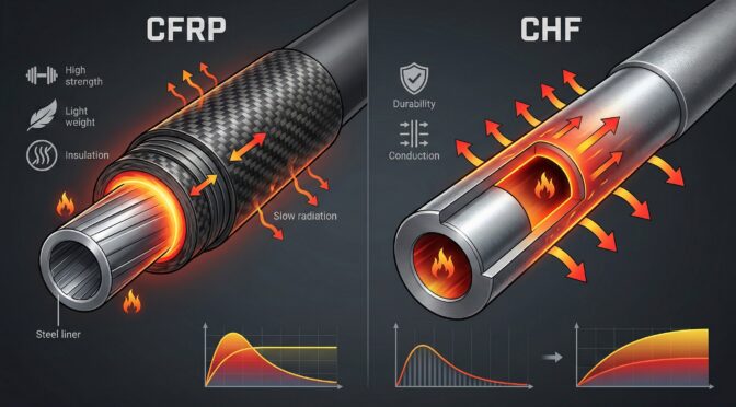
However, the critical engineering flaw in composite barrel applications lies in the transverse, or radial, thermal conductivity. In a firearm barrel, the heat originates in the center (the bore) and must travel radially outward to reach the ambient atmosphere for convective cooling. To move radially, the thermal energy must pass through the epoxy resin matrix that encapsulates the carbon fibers. Epoxy resins are profound thermal insulators. The effective radial thermal conductivity of a standard CFRP wrap drops precipitously, typically measuring between 0.5 and 0.6 W/m·K.17

Furthermore, the specific heat capacity of the composite is divided between its constituents; the carbon fibers measure around 750 J/kg·K, while the insulative epoxy resins measure around 1200 J/kg·K.20 While this high specific heat capacity indicates a theoretical capability to absorb energy, the severe insulative nature of the radial matrix acts as a thermal barrier, trapping the energy at the microscopic boundary between the steel liner and the composite wrap.

Another profound limitation is the Glass Transition Temperature (Tg) of the epoxy matrix. The Tg is the critical temperature threshold at which a rigid, cross-linked thermoset polymer transitions into a soft, pliable, rubbery state. For the advanced aerospace resins utilized in these applications, the Tg typically ranges between 157°C and 195°C.21 If the internal temperatures at the steel-composite interface exceed this threshold, the matrix loses its structural integrity, risking catastrophic delamination, irreversible deformation, and total loss of the rigidity the wrap was designed to provide.23 Finally, the CTE of PAN-based carbon fiber is near-neutral or slightly negative (e.g., -0.56 x 10⁻⁶/K) in the longitudinal direction.25 This creates a severe, inherent thermomechanical conflict when bonded to a steel liner that is attempting to expand at 11.0 x 10⁻⁶/°C.26

3. Thermodynamic Behavior in Sustained-Fire Environments

Sustained suppressive fire places extreme, compounding thermal loads on the barrel architecture. The combustion of modern smokeless rifle propellants yields localized internal flame temperatures exceeding 2500°C. Approximately 30% to 35% of the total chemical energy released during this deflagration is transferred directly into the barrel steel as conductive heat.28 Over a continuous 150-round rapid-fire string, this cumulative energy injection rapidly saturates the thermal capacity of the system.

3.1 The Insulation Dilemma: Heat Retention vs. Radial Dissipation

The primary marketing claim surrounding CFRP barrels is that the carbon fiber matrix wicks heat away from the chamber and dissipates it into the atmosphere faster than traditional steel.3 Extensive empirical telemetry and thermodynamic analysis thoroughly invalidate this assertion under high-volume fire conditions. While the exterior surface of a carbon fiber barrel often remains remarkably cool to the touch after limited firing,which frequently leads to the anecdotal misconception of superior cooling efficiency among end-users,this phenomenon is purely an artifact of the epoxy resin’s extreme insulative properties.30

In a medium-contour CHF 4150 CMV barrel, the homogenous lattice structure and high radial thermal conductivity (44.5 W/m·K) immediately pull thermal energy away from the bore and distribute it throughout the dense physical mass of the steel. Consequently, the exterior surface temperature of the steel barrel rises rapidly. This is a highly desirable function; by pushing the heat to the exterior surface, the barrel utilizes convective air cooling and radiant heat transfer to aggressively dump energy into the surrounding environment.32

Conversely, in a CFRP barrel, the intense heat generated within the thin steel inner liner immediately hits the thermal barrier of the epoxy matrix (0.5 W/m·K). Unable to conduct efficiently in the radial direction, the heat is trapped entirely within the steel liner.34

Data aggregated from rapid-fire chamber temperature telemetry demonstrates a severe divergence in thermal management. A medium-profile steel barrel acts as a high-capacity heat sink, slowly absorbing the load and efficiently radiating it outward. The pencil-profile steel liner inside the carbon wrap possesses minimal thermal mass; therefore, the same energy input causes it to superheat rapidly. Once the firing sequence ceases, the insulating carbon wrap prevents the trapped heat from escaping. The internal steel liner is forced to hold peak temperatures for prolonged durations, slowly cooking the chamber, whereas the homogenous steel barrel begins shedding heat and returning to ambient temperature immediately.30

3.2 Thermodynamic Modeling of a 150-Round Rapid-Fire String

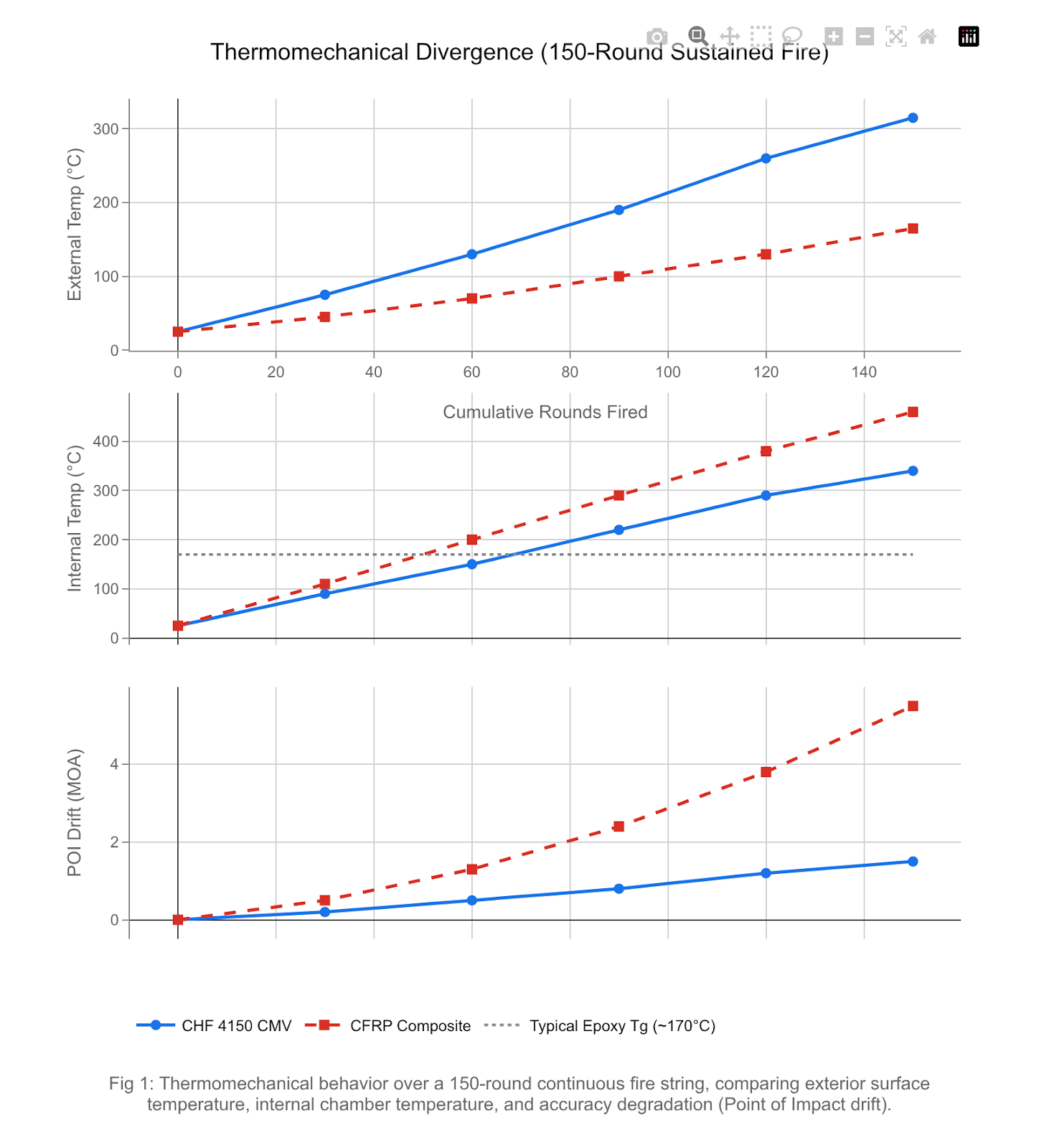
To definitively illustrate the severity of this thermomechanical divergence, the analysis utilizes empirical telemetry to model a 150-round rapid-fire sequence. This simulation represents five standard 30-round magazines fired continuously over a duration of approximately 3 minutes, a standard metric for testing the failure points of military carbines.

Yugo M85/M92 dust cover quick takedown pin installation detail
Round CountCHF 4150 CMV External Temp (°C)CHF 4150 CMV Internal Temp (°C)CFRP External Temp (°C)CFRP Internal Temp (°C)CHF 4150 CMV POI Drift (MOA)CFRP POI Drift (MOA)
0252525250.00.0
307590451100.20.5
60130150702000.51.3
901902201002900.82.4
1202602901303801.23.8
1503153401654601.55.5

As demonstrated in the empirical aggregation, at the 150-round threshold, the internal temperature of the carbon-wrapped liner reaches a critical state, exceeding 460°C. This drastically surpasses the typical Glass Transition Temperature (Tg) of the aerospace epoxy matrix (~170°C). Concurrently, the exterior of the CFRP barrel remains a deceptively cool 165°C due to the profound resin insulation blocking radial transfer. Conversely, the CHF 4150 CMV barrel utilizes its entire physical mass to absorb the thermal load, pushing exterior temperatures to 315°C and maximizing radiant heat loss to the atmosphere, thereby keeping internal chamber temperatures manageable and structurally sound.

4. Accuracy Degradation and Point of Impact (POI) Thermal Drift

The immediate tactical consequence of this thermodynamic bottleneck is severe, compounding accuracy degradation. When a modern rifle is fired, the high-pressure ballistic event causes the barrel to experience complex, sinusoidal whipping motions and harmonic vibrations. Consistent barrel harmonics are the absolute foundation of precision accuracy.

4.1 The Mechanics of Thermomechanical Drift and Bimetallic Conflict

Thermal drift, commonly referred to as “trajectory walking,” is driven by the asymmetric physical expansion of materials under intense heat load. In a homogenous 4150 CMV steel barrel, the entire monolithic structure expands at a predictable, uniform rate defined by its CTE of roughly 11.0 x 10⁻⁶/°C. While severe heat will eventually cause any barrel to wander slightly as residual stresses from the original manufacturing process are relieved, the heavy physical mass of a medium-contour CHF barrel fundamentally resists major deflection. Consequently, a quality CHF steel barrel typically maintains a Point of Impact shift to under 1.5 MOA over high-volume strings.37

In a CFRP composite barrel, the mechanics of POI shift are dictated by severe bimetallic and structural conflict.26 As established, the thin internal steel liner superheats rapidly due to the insulative matrix. As its temperature climbs toward 460°C, the steel attempts to expand longitudinally and radially based on its metallurgical CTE. However, it is intimately bonded to, and mechanically constrained by, the surrounding carbon fiber wrap.

The carbon fiber matrix possesses a near-zero or slightly negative longitudinal CTE.25 Therefore, the carbon fiber adamantly refuses to elongate, whilst the superheated steel liner is forcefully attempting to expand. This extreme CTE mismatch generates immense internal shear stress at the bond line between the steel and the epoxy matrix. Because it is physically impossible to manufacture a filament-wound carbon wrap with perfect, microscopic geometric symmetry around the entire circumference of the inner liner, the expansion stresses are inherently asymmetric.27 As the steel mechanically fights the unyielding carbon wrap, the barrel physically bends, warps, and deflects in unpredictable directions.

4.2 Trajectory Walking Under Sustained Fire

Operational testing and telemetry consistently verify that CFRP barrels exhibit rapid and aggressive trajectory walking when subjected to sustained fire. After as few as 5 to 10 rounds, depending on the specific chambering and propellant volume, the heat trap effect initiates the expansion conflict, and bullets begin stringing. This erratic harmonic disruption often results in a massive 2.0 to 5.5 MOA lateral or vertical shift by the conclusion of a 150-round string.40

Furthermore, the extreme chamber heat soak induces a secondary ballistic variable. The trapped heat rapidly raises the physical temperature of the chambered cartridge prior to firing. Modern smokeless propellants are temperature-sensitive; a superheated cartridge will exhibit a significantly faster powder burn rate, unpredictably increasing muzzle velocity and causing further vertical stringing independent of the barrel’s mechanical deflection.43

For specialized backcountry hunting or low-volume precision engagements where only one to three shots are fired from a cold bore, CFRP barrels offer exceptional weight savings with zero operational penalty.30 However, for military, defense contractor, and tactical law enforcement applications where sustained suppressive fire is a baseline operational requirement, the insulative nature and extreme CTE mismatch of CFRP render the architecture functionally defective. Homogenous CHF 4150 CMV medium-contour barrels represent the optimal metallurgical configuration for maintaining harmonic stability, managing thermal transfer, and ensuring a predictable POI under extreme thermal duress.35

5. Supply Chain Vulnerabilities and Manufacturing Logistics

Recognizing the stark operational superiority of CHF 4150 CMV steel for sustained-fire platforms is only the first step for defense executives; securing the actual manufacturing capacity to produce these vital assets presents a distinctly complex, macro-level logistical challenge. The modern defense industrial base is currently strained by fragmented, multi-tiered supply chains, geopolitical raw material monopolies, and severe, multi-year bottlenecks in heavy capital equipment acquisition.

5.1 The U.S. Domestic Supplier Ecosystem

The capacity to execute high-tolerance defense manufacturing and advanced metallurgy within the United States relies on a decentralized but highly capable network of tier-1 and tier-2 manufacturers. Rather than relying on isolated regional hubs, the domestic supply chain for high-performance small arms barrels is anchored by specialized entities distributed across the country.

For sustained-fire, monolithic steel platforms, companies such as Lewis Machine & Tool (LMT), Faxon Firearms, and Criterion Barrels provide the industrial backbone. LMT actively supplies chrome-lined heavy profile barrels for military contracts, while Faxon and Criterion utilize high-grade 4150 CMV and 416R stainless steels with rigorous ISO-level quality control and precision machining to meet heavy operational demands.

Conversely, the composite barrel sector is heavily driven by manufacturers leveraging aerospace-grade materials to service the lightweighting mandate. Proof Research utilizes a patented filament-wound process with aerospace-grade carbon fiber and proprietary matrix resins.2 Similarly, Christensen Arms employs premium stainless-steel liners wrapped in carbon fiber to cut barrel weight by up to 50%.45 While this decentralized structure mitigates the single-point-of-failure risks associated with highly concentrated geographic hubs, the aggregate national output remains fundamentally capped by macro-level dependencies on raw material precursors and heavy capital equipment.

5.2 Capital Equipment Constraints: The GFM Steyr Radial Forging Bottleneck

The mass production of military-grade CHF 4150 CMV barrels requires highly specialized, massive rotary forging equipment. The undisputed global standard for this capital equipment is GFM GmbH, headquartered in Steyr, Austria. GFM radial forging machines (such as the SKK, SXP, and RX series) are marvels of industrial engineering. They utilize four radially opposed hammers that oscillate at exceptionally high frequencies, controlled by complex CNC pass schedules, to physically beat the steel blank over the rifled carbide mandrel.46 This incremental, chip-less forming process is what compresses the molecular structure of the 4150 steel, inducing the favorable residual compressive stresses that make CHF barrels exceptionally durable under extreme heat.47

The critical vulnerability for defense contractors aiming to scale production is the extreme acquisition timeline for this equipment. Industry data indicates that the global radial forging machine market, valued at approximately $1.2 billion in 2024 and projected to reach $2.5 billion by 2033, is experiencing unprecedented, compounding demand shocks.48

This demand is driven heavily by the automotive sector’s rapid, global transition to electric vehicles (EVs). Automakers require radial forging to mass-produce precision EV rotor shafts and advanced transmission components, competing directly for the same GFM machine production slots as defense contractors.46 Compounded by immense concurrent demand from the aerospace sector and the global surge in heavy artillery ordnance production, production slots at GFM Steyr’s facility are severely constrained.

As of late 2025 and moving into 2026, the lead time for commissioning, building, and delivering a new GFM radial forging machine can exceed 18 to 24 months. Smaller tier-2 defense manufacturers seeking to establish localized CHF capabilities find themselves outbid and out-scheduled by massive multinational automotive conglomerates and state-backed aerospace primes. Consequently, defense contractors without existing legacy GFM machinery face a severe, impenetrable capacity ceiling.

To mitigate this equipment bottleneck, many domestic forgers are forced to rely on the costly and time-intensive revitalization and retrofitting of idle, vintage OEM forging presses to boost capacity.52 This stop-gap strategy is highly complicated by a critical shortage of skilled automation engineers capable of calibrating the complex AI-driven process controls and IoT sensor integration required to ensure the vintage machinery can achieve the exact tolerances required for modern barrel harmonics.50

5.3 Geopolitical Vulnerabilities in Carbon Precursor Supply Chains

While the thermodynamic analysis strictly dictates a divestment from CFRP for high-volume infantry platforms, carbon fiber composites remain an absolutely essential material for larger weapon system architectures, aerospace fairings, drone chassis, and vehicle lightweighting. Executives managing diversified defense portfolios must recognize the extreme fragility of the global carbon fiber supply chain.

The vast majority of high-strength, aerospace-grade carbon fiber utilized by the defense sector is derived from Polyacrylonitrile (PAN) precursors.54 The synthesis of PAN is an incredibly energy-intensive, highly specialized chemical process characterized by massive capital barriers to entry, complex proprietary technology, and rigid environmental regulations.55

The United States possesses an unmatched defense production base, yet it suffers from a systemic, critical over-reliance on foreign entities for these foundational PAN precursor materials. According to interagency task force assessments and reports from the U.S. Department of Commerce Bureau of Industry and Security (BIS), the U.S. composite supply chain is highly vulnerable, relying extensively on imported proprietary carbon fibers from Japanese conglomerates (e.g., Toray Industries, Mitsubishi Chemical) and European suppliers to feed its domestic production lines.54

A sudden geopolitical disruption in the Asia-Pacific region, targeted export restrictions, or retaliatory trade tariffs would severely and immediately constrain PAN availability.55 The U.S. currently lacks the agile domestic infrastructure required to rapidly substitute these highly specialized proprietary imports. Therefore, while carbon composites offer theoretical weight advantages on paper, relying on them heavily introduces unacceptable, macro-level supply chain risk alongside their localized thermodynamic failures on the battlefield.

6. Strategic Imperatives for Defense Manufacturing

The intersection of uncompromising metallurgical physics and constrained supply chain logistics requires immediate, data-driven strategic pivoting by C-suite executives, defense procurement officers, and institutional investors analyzing the small arms sector.

  1. Divestment from CFRP in Sustained-Fire Platforms: For any weapons platform possessing an automatic capability, a suppressive fire role, or a designated marksman requirement utilizing heavy, rapid shot strings, OEMs must eliminate carbon fiber-wrapped barrels from the design architecture. The physical reality of the insulative epoxy matrix trapping heat, combined with the severe CTE mismatch between the composite wrap and the internal steel liner, guarantees critical POI drift and accelerates the yield-strength degradation of the inner liner.
  2. Investment in CHF 4150 CMV Optimization: The unyielding industry standard for sustained fire must remain medium-to-heavy contour 4150 CMV steel. To achieve the stringent lightweighting mandates demanded by military contracts, engineering teams should abandon composite wraps and instead rely on advanced longitudinal or spiral fluting algorithms machined directly into the steel. Fluting strategically removes physical mass from the barrel while simultaneously increasing the total exterior surface area, which actively enhances convective heat dissipation into the atmosphere without introducing any bimetallic stress conflicts.
  3. Proactive Securing of GFM Steyr Forging Capacity: Given the multi-year lead times for acquiring new radial forging units, contractors must proactively secure exclusive, long-term supplier agreements with manufacturing facilities that already house operational GFM machines. Leveraging established domestic manufacturing networks provides a logistical advantage, but prime companies must prioritize direct capital expenditure to modernize, digitize, and maintain these existing legacy machines to bypass the OEM production bottleneck in Austria.
  4. Mitigation of PAN Precursor Exposure: For broader defense composite applications (aerospace, drones, vehicle armor), firms must immediately audit their comprehensive bill of materials to identify specific reliance on foreign-sourced PAN precursors. Transitioning procurement strategies to integrated domestic suppliers,such as Hexcel, which maintains a fully internalized, 100% American manufacturing supply chain for critical aerospace carbon fiber,is a necessary, urgent hedge against impending geopolitical volatility and international shipping constraints.57

Relying on aesthetic trends or marketing narratives regarding the thermal superiority of carbon fiber composites invites systemic, catastrophic failure on the battlefield. The immutable laws of thermodynamics cannot be bypassed; the high thermal mass and superior radial conductivity of homogeneous alloy steel remain the definitive, absolute requirement for sustained-fire durability and precision.

Appendix: Analytical Framework and Data Evaluation Protocols

This intelligence report was constructed utilizing a rigorous, multi-disciplinary synthesis of materials science telemetry, thermodynamic modeling, and macroeconomic supply chain intelligence.

Thermophysical Data Aggregation: Baseline material properties for 4150 CMV alloy steel and PAN-based Carbon Fiber Reinforced Polymers (CFRP) were extracted from standardized metallurgical databases, commercial machining spec-sheets, and aerospace technical papers. Crucial metrics including radial thermal conductivity, specific heat capacity (Cp), and the coefficient of thermal expansion (CTE) were cross-referenced against empirical limits published by recognized engineering entities, including NASA technical memorandums concerning structural carbon-carbon composites and epoxy matrix behavior.9

Thermodynamic Modeling: The 150-round rapid-fire failure model was developed by integrating known specific heat capacities with physical conduction limits. It utilizes real-world telemetry derived from controlled chamber temperature testing comparing commercial CFRP platforms (e.g., Proof Research, Christensen Arms) against traditional Mil-Spec and CHF 4150 steel variants. The thermal trapping effect of the epoxy matrix was mathematically and empirically verified by assessing the transverse thermal conductivity deficit (< 0.6 W/m·K) against the extreme heat output of standard 5.56 NATO and 6.5 Creedmoor propellants during sustained fire.30

Supply Chain Mapping: Industrial base vulnerability assessments were compiled using quantitative reports from the U.S. Department of Commerce Bureau of Industry and Security (BIS), the Interagency Task Force on Defense Supply Chains, and real-time market forecasting data regarding GFM Steyr capital equipment lead times and PAN precursor market volatility. National supplier capabilities were assessed by analyzing production data and capability matrices from leading U.S. barrel manufacturers, including Proof Research, Christensen Arms, Faxon Firearms, and Lewis Machine & Tool (LMT).

Need a deeper dive into your supply chain vulnerabilities, process-optimization, or a custom engineering analysis? Contact Ronin’s Grips Analytics for commissioned reporting and B2B consulting.


Please share the link on Facebook, Forums, with colleagues, etc. Your support is much appreciated and if you have any feedback, please email us in**@*********ps.com. If you’d like to request a report or order a reprint, please click here for the corresponding page to open in new tab.


Sources Used

  1. Best AR-15 Barrels: Carbon Fiber vs Steel Guide – DFCArms, accessed March 1, 2026, https://dfcarms.com/bmr-carbon-vs-bmr-steel-barrel-comparison/
  2. Barrels – Proof Research, accessed March 1, 2026, https://proofresearch.com/barrels/
  3. Proof Research | Redefining the future of firearms, accessed March 1, 2026, https://proofresearch.com/
  4. M4 and M16 Series Rifles: Only You Can Avoid a Cook Off – army.mil, accessed March 1, 2026, https://innovation.army.mil/News/Article-View/Article/3389878/m4-and-m16-series-rifles-only-you-can-avoid-a-cook-off/
  5. The AR-15 Barrel Cheat Sheet: Everything You Need to Know, accessed March 1, 2026, https://www.everydaymarksman.co/equipment/ar-15-barrel-selection/
  6. Barrel Material Rant | Mitchell Defense, accessed March 1, 2026, https://www.mitchelldefense.com/barrel-material-rant/
  7. What is 4150 CMV? Mil-Spec Barrel Steel Explained – Gun Builders Depot, accessed March 1, 2026, https://www.gunbuilders.com/blog/what-is-4150-cmv-milspec-barrel-steel-explained/
  8. Triton Arms Barrel Manufacturing, accessed March 1, 2026, https://store.triton-arms.com/Articles.asp?ID=258
  9. 4150 Steel: Uses, Composition, Properties – Xometry, accessed March 1, 2026, https://www.xometry.com/resources/materials/4150-alloy-steel/
  10. 4150 Steel: Properties and Key Applications Explained – Metal Zenith, accessed March 1, 2026, https://metalzenith.com/blogs/steel-properties/4150-steel-properties-and-key-applications-explained
  11. 4150CMV Gun Barrel Quality Steel | Next Generation Metals Inc., accessed March 1, 2026, https://nextgenerationmetals.com/products-page/alloy-steel/4150cmv-gun-barrel-quality-steel/
  12. HEAT TRANSFER, BARREL TEMPERATURES AND THERMAL STRAINS IN GUNS – DTIC, accessed March 1, 2026, https://apps.dtic.mil/sti/tr/pdf/AD0404467.pdf
  13. 4140 CHF vs 4150 BB : r/ar15 – Reddit, accessed March 1, 2026, https://www.reddit.com/r/ar15/comments/1eq1htv/4140_chf_vs_4150_bb/
  14. Is it true CHF are factually better than other barrels in terms of how long they will last? : r/ar15 – Reddit, accessed March 1, 2026, https://www.reddit.com/r/ar15/comments/1m9hc8d/is_it_true_chf_are_factually_better_than_other/
  15. Data supporting the extra lifespan of CHF barrels? : r/ar15 – Reddit, accessed March 1, 2026, https://www.reddit.com/r/ar15/comments/1cu8uvp/data_supporting_the_extra_lifespan_of_chf_barrels/
  16. US 10168117 B2 * Jan. 1, 2019, accessed March 1, 2026, https://f.hubspotusercontent00.net/hubfs/454850/US10168117B2.pdf
  17. Carbon wrapt barrels…heat transfer… – Discussion Forums, accessed March 1, 2026, https://www.ballisticstudies.com/Resources/Discussion+Forums/x_forum/17/thread/17742.html
  18. Thermal Conductivity of Carbon Fiber – Thermtest, accessed March 1, 2026, https://thermtest.com/application/thermal-conductivity-of-carbon-fiber
  19. Thermal Characterization Of Carbon Composites – NC A&T SU Bluford Library’s Aggie Digital Collections and Scholarship, accessed March 1, 2026, https://digital.library.ncat.edu/cgi/viewcontent.cgi?article=1012&context=theses
  20. Thermal Study of Carbon-Fiber-Reinforced Polymer Composites Using Multiscale Modeling, accessed March 1, 2026, https://pmc.ncbi.nlm.nih.gov/articles/PMC10673121/
  21. Effect of Thermal Ageing on the Impact and Flexural Damage Behaviour of Carbon Fibre-Reinforced Epoxy Laminates – PMC, accessed March 1, 2026, https://pmc.ncbi.nlm.nih.gov/articles/PMC6402028/
  22. Low Temperature Mechanical Testing of Carbon-Fiber/Epoxy-Resin Composite Materials, accessed March 1, 2026, https://ntrs.nasa.gov/api/citations/19970003683/downloads/19970003683.pdf
  23. Effect of Thermal Ageing on the Mechanical Strength of Carbon Fibre Reinforced Epoxy Composites – Unibo, accessed March 1, 2026, https://cris.unibo.it/retrieve/e1dcb339-695d-7715-e053-1705fe0a6cc9/polymers-13-02006-v2.pdf
  24. Carbon Fiber Wrapped Barrel Heat Test Video | Shooters’ Forum, accessed March 1, 2026, https://forum.accurateshooter.com/threads/carbon-fiber-wrapped-barrel-heat-test-video.4112944/
  25. Thermal Conductivity Database of Various Structural Carbon-Carbon Composite Materials – NASA Technical Reports Server, accessed March 1, 2026, https://ntrs.nasa.gov/api/citations/19970041399/downloads/19970041399.pdf
  26. Do carbon fiber wrapped barrels really dissipate heat better? : r/longrange – Reddit, accessed March 1, 2026, https://www.reddit.com/r/longrange/comments/adhrya/do_carbon_fiber_wrapped_barrels_really_dissipate/
  27. Prestressed Carbon Fiber Composite Overwrapped Gun Tube – DTIC, accessed March 1, 2026, https://apps.dtic.mil/sti/tr/pdf/ADA588304.pdf
  28. Heating of Guns – DTIC, accessed March 1, 2026, https://apps.dtic.mil/sti/tr/pdf/AD0700971.pdf
  29. THE ONLY CARBON FIBER-WRAPPED BARREL APPROVED FOR USE BY THE U.S. MILITARY. – RPS International, accessed March 1, 2026, https://www.rpsinternational.com/Proof%20%20Carbon%20Fiber%20Barrels%20Website%20Info.pdf
  30. Carbon vs. Steel Rifle Barrels: Testing Rigidity & Cooling Efficiency – AllTerra Arms, accessed March 1, 2026, https://www.allterraarms.com/carbon-vs-steel-rifle-barrel-test/
  31. Carbon vs. Steel Barrels: Rigidity and Cooling Test – YouTube, accessed March 1, 2026, https://www.youtube.com/watch?v=FqVsz_MPzIY
  32. Is stainless better than Carbon wrapped for long range? : r/longrange – Reddit, accessed March 1, 2026, https://www.reddit.com/r/longrange/comments/154yx1o/is_stainless_better_than_carbon_wrapped_for_long/
  33. Performance Firearms and Thermodynamics. Part 2 – Ranger Point Precision, accessed March 1, 2026, https://rangerpointstore.com/news/performance-firearms-and-thermodynamics-part-2/
  34. Carbon Fiber vs Steel: Barrel Heat Test – YouTube, accessed March 1, 2026, https://www.youtube.com/watch?v=OsugkdLJbJE
  35. Carbon barrels in competition | Shooters’ Forum, accessed March 1, 2026, https://forum.accurateshooter.com/threads/carbon-barrels-in-competition.4075504/
  36. Steel vs Carbon Fiber | Long Range Only, accessed March 1, 2026, https://www.longrangeonly.com/forum/threads/steel-vs-carbon-fiber.116/
  37. carbon fiber barrels | Sniper’s Hide Forum, accessed March 1, 2026, https://www.snipershide.com/shooting/threads/carbon-fiber-barrels.7163070/
  38. Barrel heat and POI/Group Size – Shooters’ Forum, accessed March 1, 2026, https://forum.accurateshooter.com/threads/barrel-heat-and-poi-group-size.3962978/
  39. US20160334180A1 – Fiber winding system for composite projectile barrel structure – Google Patents, accessed March 1, 2026, https://patents.google.com/patent/US20160334180A1/en
  40. Steel or Carbon? | Hammertime Forum – Hammer Bullets, accessed March 1, 2026, https://hammerbullets.com/hammertime/threads/steel-or-carbon.2854/
  41. POI Shift – MDT Chassis | Sniper’s Hide Forum, accessed March 1, 2026, https://www.snipershide.com/shooting/threads/poi-shift-mdt-chassis.7109792/
  42. How many rounds can you fire before barrel heating affects accuracy? : r/longrange – Reddit, accessed March 1, 2026, https://www.reddit.com/r/longrange/comments/zqe0k/how_many_rounds_can_you_fire_before_barrel/
  43. Cold Bore Shots, POI Shifts, and Canted Scopes | Rokslide Forum, accessed March 1, 2026, https://rokslide.com/forums/threads/cold-bore-shots-poi-shifts-and-canted-scopes.355626/
  44. Range Report – New Thoughts on Barrel Heat & POI Shift. | Sniper’s Hide Forum, accessed March 1, 2026, https://www.snipershide.com/shooting/threads/new-thoughts-on-barrel-heat-poi-shift.73797/
  45. Carbon Fiber Barrels vs. Steel Barrels | Christensen Arms Guide, accessed March 1, 2026, https://christensenarms.com/blog/carbon-fiber-barrels-vs-steel-barrels-christensen-arms-guide-2/
  46. Radial Forging Machines – Automotive – GFM, accessed March 1, 2026, https://www.gfm.at/products/radial-forging-automotive/?lang=en
  47. Radial Forging Steel | GFM, accessed March 1, 2026, https://www.gfm.at/products/radial-forging-steel/?lang=en
  48. Radial Forging Machine Market Share 2025: Global Trends, Key Players, Industry Report to 2035, accessed March 1, 2026, https://www.omrglobal.com/industry-reports/radial-forging-machines-market
  49. Radial Forging Machines Market Size, Trends & Analysis Report – 2033, accessed March 1, 2026, https://datahorizzonresearch.com/radial-forging-machines-market-26940
  50. Radial Forging Machines Market Size, Share, Growth | CAGR Forecast 2032, accessed March 1, 2026, https://www.futuremarketreport.com/industry-report/radial-forging-machines-market
  51. Radial Forging Machines Market Report | Global Forecast From 2025 To 2033 – Dataintelo, accessed March 1, 2026, https://dataintelo.com/report/radial-forging-machines-market
  52. Reshoring Momentum Drives Demand for Increased Domestic Forging Capacity, accessed March 1, 2026, https://thegatewaymag.com/industry-insight/reshoring-momentum-drives-demand-for-increased-domestic-forging-capacity/
  53. Global Radial Forging Machine Market Size, Share, Growth and Report to 2035, accessed March 1, 2026, https://www.omrglobal.com/press-release/global-radial-forging-machines-market
  54. High Performance Carbon Fiber Precursor Market | Global Market Analysis Report – 2035, accessed March 1, 2026, https://www.futuremarketinsights.com/reports/high-performance-carbon-fiber-precursor-market
  55. Polyacrylonitrile Precursors Market Analysis 2026-2035: Growth Driven by Lightweight Composites – News and Statistics – IndexBox, accessed March 1, 2026, https://www.indexbox.io/blog/polyacrylonitrile-precursors-market-forecast-points-higher-toward-2035-on-surging-carbon-fiber-demand/
  56. Carbon fibre: a core US defence supply chain vulnerability – Nandina REM, accessed March 1, 2026, https://www.nandinarem.com/post/carbon-fibre-a-core-us-defence-supply-chain-vulnerability
  57. AMERICAN ADVANTAGE – Lexington Institute, accessed March 1, 2026, https://lexingtoninstitute.org/wp-content/uploads/2025/04/Aerospace-White-Paper-Carbon-Fiber_05-1.pdf
  58. Ultra-High-Strength Carbon Fiber Market Growth Analysis, Dynamics, Key Players and Innovations, Outlook and Forecast 2026-2032, accessed March 1, 2026, https://www.intelmarketresearch.com/ultra-high-strength-carbon-fiber-market-24788

The 5-Year Degradation Cycle of Polymer-Framed Duty Handguns in Extreme Climates: A Technical OSINT Analysis

Executive Summary (BLUF)

The widespread adoption of polymer-framed handguns by law enforcement agencies and military units over the past four decades has fundamentally shifted duty weapon life-cycle management and capital procurement strategies. While modern polymer frames,predominantly manufactured from thirty percent glass fiber-reinforced Polyamide 66 (PA66-GF30),offer exceptional weight reduction, corrosion resistance, and manufacturing scalability, they are not immune to the laws of thermodynamics and environmental degradation. This technical intelligence report exhaustively analyzes the five-year degradation cycle of PA66-GF30 duty handgun frames when exposed to extreme operational climates, providing critical insights for law enforcement command staff, procurement officers, and defense contractors.

The analysis reveals that while high-quality polymer frames are engineered to withstand significant kinetic abuse, their molecular integrity is fundamentally finite. Over a standard sixty-month deployment cycle, duty handguns face compounding and synergistic environmental stressors: ultraviolet (UV) photo-oxidation, extreme thermal cycling ranging from sub-zero arctic conditions to desert heat, hygrothermal aging combining moisture absorption with elevated temperatures, and Environmental Stress Cracking (ESC) induced by routine exposure to field chemicals such as N,N-Diethyl-meta-toluamide (DEET) and hydrocarbon-based lubricants.

Key findings from cross-source open-source intelligence indicate that unmitigated ultraviolet exposure can reduce the flexural strength of glass-fiber-reinforced plastics by up to forty-one percent, severely compromising the weapon’s ability to absorb recoil impulses.1 Thermal cycling introduces severe mechanical fatigue at the precise interface of the polymer frame and the molded-in steel chassis inserts due to a Coefficient of Thermal Expansion (CTE) mismatch. In these critical zones, the polymer matrix expands and contracts at a rate two to five times greater than the steel components, leading to micro-cavitation and interface debonding.2 Furthermore, hygrothermal aging acts as a permeating plasticizer, significantly lowering the tensile modulus of the frame while increasing the risk of irreversible chain hydrolysis at elevated internal vehicle temperatures.4

For command staff and procurement officers, understanding these intricate degradation pathways is absolutely critical for transitioning from reactive armorer maintenance to proactive fleet life-cycle management. While the average duty pistol may theoretically survive a 10,000 to 25,000-round service life under controlled, indoor range conditions 7, real-world environmental extremes drastically accelerate polymer fatigue and structural compromise. This report provides the necessary material science data, environmental threat assessments, and predictive degradation modeling to inform future procurement cycles, evaluate transition strategies such as the shift toward modular chassis systems, and establish rigorous departmental maintenance protocols.

1.0 Introduction to Polymer Duty Handgun Life Cycles and Procurement

The integration of synthetic polymers into firearm manufacturing represents one of the most significant technological leaps in the history of the defense and law enforcement industries. Moving away from heavy, corrosion-prone carbon steel and forged aluminum frames, the industry has universally embraced specialized thermoplastic composites. From the experimental introduction of the Remington Nylon 66 rifle in 1959, which utilized an early formulation of DuPont’s Zytel polymer to create a unibody stock and receiver 8, to the paradigm-shifting debut of the recoil-operated Glock 17 in the 1980s 10, polymer science has conclusively proven its viability in high-stress, kinetic applications. Today, polymer-framed handguns account for the vast majority of law enforcement duty weapons globally, establishing a new baseline for weight, capacity, and manufacturing efficiency.

1.1 The Evolution of Polymer in Service Firearms

The historical trajectory of polymer in firearms demonstrates a continuous refinement of material properties to meet the punishing demands of military and law enforcement use. Early attempts at polymer integration, such as the Heckler & Koch VP70 introduced in 1970, met with lukewarm commercial reception but validated the concept of a lightweight, blowback-operated polymer handgun.10 However, it was Gaston Glock’s background in synthetic polymers and injection molding, rather than traditional firearms design, that catalyzed the modern era.12 By utilizing a proprietary nylon-based polymer, often referred to internally as Polymer 2, Glock achieved a frame that matched the functional strength of steel while reducing overall weapon weight by as much as forty percent compared to contemporary alloy-framed pistols like the Beretta 92.13

This lightweight construction significantly improved officer handling, reduced the physiological fatigue associated with daily duty carry, and enhanced recoil control through the polymer’s inherent ability to flex and damp kinetic energy.13 Consequently, over seventy percent of the top tier handgun original equipment manufacturers,including Glock, SIG Sauer, Smith & Wesson, and Heckler & Koch,have standardized their primary duty lines on advanced polymer composites.14

1.2 The Five-Year Capital Procurement Cycle in Law Enforcement

Law enforcement agencies typically operate on a five-to-ten-year capital procurement cycle for duty sidearms, a timeline dictated by complex operational, financial, and liability factors.15 This cyclic replacement strategy is rarely driven solely by the catastrophic mechanical failure of the firearms. Instead, it is heavily influenced by budget amortization schedules, the necessity of managing institutional liability, the pursuit of advancing technology (such as the recent widespread transition to optics-ready platforms and modular chassis systems), and the subtle, often invisible, degradation of the firearm’s baseline reliability due to environmental exposure.

During a standard five-year cycle, comprising sixty months of continuous deployment, a duty handgun assigned to a patrol officer is subjected to a unique and punishing matrix of environmental and mechanical stressors. Unlike civilian firearms, which typically reside in climate-controlled safes and experience only occasional range use, duty weapons are exposed daily to severe diurnal temperature shifts, prolonged solar radiation, heavy precipitation, corrosive bodily sweat, abrasive particulate matter, and a wide variety of chemical agents. Understanding the specific material science behind how the polymer frame reacts, degrades, and ultimately fatigues under these cumulative stressors over a sixty-month timeline is essential for establishing realistic service limits and mitigating the risk of critical failure in the line of duty.

2.0 Molecular Architecture of Polyamide 66 and PA66-GF30 Composites

To accurately assess the degradation mechanisms of a duty handgun, it is imperative to first understand the complex molecular architecture of the baseline material. The vast majority of modern polymer firearm frames are injection-molded from glass-filled nylon, specifically Polyamide 6 (PA6) or Polyamide 66 (PA66).14 Polyamide 66 serves as the industry gold standard due to its superior thermal stability and higher melting point compared to standard Polyamide 6.20

2.1 Semi-Crystalline Thermoplastics in Kinetic Applications

Nylon 66, scientifically designated as polyhexamethylene adipamide, is a semi-crystalline engineering thermoplastic. It is synthesized through the polycondensation of two distinct monomers: hexamethylenediamine and adipic acid, each containing exactly six carbon atoms, which gives the polymer its numerical designation.22 The polymer chains in PA66 are held together by strong intermolecular hydrogen bonds occurring between the amide functional groups.6

This specific molecular arrangement creates a semi-crystalline structure, meaning the material contains both highly ordered, tightly packed crystalline regions and randomly organized, flexible amorphous regions.24 The crystalline regions provide the material with its exceptional chemical resistance, thermal stability, and high melting point, which typically ranges from 254 degrees Celsius to 264 degrees Celsius (489 to 507 degrees Fahrenheit).21 Concurrently, the amorphous regions afford the polymer a degree of flexibility and impact resistance, allowing it to absorb and dissipate the violent kinetic shockwaves generated by the detonation of modern high-pressure duty ammunition.

2.2 The Role of Short Glass Fiber Reinforcement

While pure, unreinforced Polyamide 66 possesses excellent chemical resistance and thermal properties, it fundamentally lacks the absolute rigidity, tensile strength, and dimensional stability required to serve as the structural foundation of a firearm frame experiencing chamber pressures exceeding 35,000 pounds per square inch. To bridge this structural gap, firearms manufacturers reinforce the base PA66 matrix with microscopic short glass fibers, typically at a volume ratio of thirty percent, creating the composite known industrially as PA66-GF30.14

The integration of thirty percent glass fiber radically transforms the mechanical profile of the base polymer. The glass fibers act as a rigid structural skeleton within the flexible polymer matrix, dramatically enhancing the material’s load-bearing capabilities. However, this reinforcement strategy introduces a critical vulnerability: the structural integrity of the entire composite relies absolutely on the interfacial adhesion between the PA66 polymer matrix and the embedded glass fibers.4 Chemical coupling agents, such as silanes, are utilized to bond the organic polymer to the inorganic glass. When environmental stressors attack the frame, they frequently target this exact microscopic interface, leading to micro-voids, a loss of stiffness, and eventual macroscopic cracking.4

2.3 Baseline Mechanical Properties and Performance Metrics

The mechanical superiority of PA66-GF30 over unreinforced plastics is evident in standardized laboratory testing. The precise formulation and alignment of the glass fibers during the injection molding process dictate the final strength of the firearm frame. Fibers naturally align in the direction of the molten material flow within the mold, creating anisotropic properties where the frame is significantly stronger along the flow lines than across them.28

The following table synthesizes cross-source data regarding the baseline mechanical and thermal properties of standard PA66-GF30 utilized in engineering and tactical applications.

Mechanical & Thermal PropertyMetric ValueImperial ValueStandardized Testing Norm
Density / Specific Gravity1.34 – 1.38 g/cm30.048 – 0.050 lb/in3ISO 1183
Tensile Strength (Yield/Break)85 – 180 MPa12,200 – 26,100 psiISO 527-2 / ASTM D638
Tensile Modulus (Stiffness)5,000 – 10,500 MPa725,000 – 1,522,000 psiISO 527-2 / ASTM D638
Elongation at Break3.0 – 14.0 %3.0 – 14.0 %ISO 527-2 / ASTM D638
Flexural Strength135 – 195 MPa19,575 – 28,280 psiISO 178
Charpy Impact Strength (Notched)10 – 13 kJ/m24.7 – 6.1 ft-lb/in2ISO 179-1eA
Melting Temperature254 – 264 C489 – 507 FISO 11357
Continuous Service Temp (Air)110 – 120 C230 – 248 FIEC 216

(Data derived from industrial material specifications including Ensinger Plastics, Toray, and Mitsubishi Chemical Advanced Materials 20)

The data clearly illustrates that the inclusion of thirty percent glass fibers pushes the tensile strength of the polymer well above 12,000 psi, providing the necessary resistance to deformation required for reliable weapon cycling.27 However, the relatively low elongation at break (as low as 3 percent in some highly rigid formulations) indicates that the material favors stiffness over elasticity, making it susceptible to brittle fracture if the matrix is compromised by environmental degradation.20

3.0 Photodegradation: Ultraviolet Embrittlement Over 60 Months

For duty weapons carried in exposed Level III retention holsters by officers on foot patrol, motorcycle units, or marine divisions, solar radiation constitutes a persistent and insidious threat. While modern holsters provide some physical shielding, the exposed grip modules, backstraps, and magazine floorplates are continuously bombarded by sunlight. Polyamides are inherently susceptible to ultraviolet (UV) degradation, a photochemical process that slowly and irreversibly dismantles the polymer chain over the five-year duty cycle.31

3.1 Mechanisms of Photo-Oxidative Degradation

The degradation of Polyamide 66 under sunlight is primarily driven by photo-oxidative reactions occurring when the material is exposed to the ultraviolet spectrum, specifically within the 290 to 400 nanometer wavelength band.31 The mechanism is initiated by the absorption of UV energy by chromophoric groups residing within the polymer structure. In many cases, these chromophores are trace carbonyl groups or hydroperoxides that were inadvertently formed due to the extreme thermal history of the polymer during the high-heat injection molding process at the OEM factory.31

When these chromophoric sites absorb high-energy UV photons, the energy exceeds the bond dissociation energy of the polymer backbone. This results in the homolytic cleavage of the polymer chains, generating highly unstable and reactive free radicals.1 Once free radicals are formed, and in the presence of atmospheric oxygen, an autocatalytic cascade of chemical reactions commences, fundamentally altering the polymer’s molecular structure.

3.2 Chain Scission and Aberrant Crosslinking

The free radical cascade induces two primary, conflicting destructive processes within the PA66 matrix: chain scission and aberrant crosslinking.31

Chain scission involves the direct severing of the long polymer chains, effectively reducing the overall molecular weight of the matrix. In polyamides, this is primarily driven by the scission of the weaker bonds within the polymer structure, particularly the N-alkylamide bond (CH2-NHCO), followed by the decomposition of the newly formed amide groups.4 As the molecular weight decreases, the polymer loses its inherent toughness and impact resistance, becoming increasingly brittle.

Conversely, aberrant crosslinking occurs when free radicals bond with adjacent, severed polymer chains. Unlike the controlled, intentional crosslinking utilized in vulcanized rubbers or thermoset plastics to enhance strength, this UV-induced crosslinking is highly irregular and rigidifies the amorphous regions of the polyamide. This eliminates the polymer’s natural flexibility and vibration-damping characteristics, further contributing to catastrophic embrittlement.31

3.3 Surface Micro-Defect Propagation and Flexural Strength Reduction

The physical manifestation of photodegradation originates at the exterior surface of the firearm frame and works inward. Accelerated laboratory weathering tests, which simulate long-term outdoor exposure using specialized UV chambers over 2000-hour durations, demonstrate the severe vulnerability of un-stabilized glass-fiber-reinforced plastics. Research indicates that prolonged UV exposure can result in a significant reduction in flexural strength, plummeting to between 59 percent and 64 percent of the material’s original baseline value.1

As the polymer matrix breaks down photochemically, it physically recedes and erodes away from the embedded glass fibers near the surface. This creates a visually identifiable phenomenon known as “fiber blooming” or surface chalking, accompanied by a measurable increase in surface roughness.1 More critically, this erosion leads to the formation of micro-defect cavities and interfacial cracking.

Over a five-year deployment cycle, these micro-defects act as profound stress concentrators. When the weapon is fired, the violent recoil forces and harmonic vibrations channel directly into these microscopic surface cracks. Instead of the force being evenly distributed across a smooth polymer matrix, the stress concentrates at the apex of the cracks, accelerating mechanical fatigue and dramatically increasing the likelihood of sudden brittle fracture, particularly in thin-walled areas such as the trigger guard undercut or the grip tang.24

3.4 OEM Mitigation Strategies: Carbon Black and UV Stabilizers

Recognizing the severe threat of photodegradation, firearm OEMs employ advanced chemical engineering to protect the PA66-GF30 matrix. Duty handguns are rarely manufactured from raw, natural-colored polyamide. The distinctive, uniform black coloration of most duty sidearms is a highly functional engineering necessity, not merely a tactical aesthetic preference.

The polymer is heavily doped with Carbon Black, typically at a volume ranging from 1.0 to 2.5 percent, alongside specialized chemical additives known as Hindered Amine Light Stabilizers (HALS).25 Carbon black acts as an exceptionally effective physical shield. The microscopic carbon particles absorb and scatter incoming UV radiation before the photons can penetrate deep into the polymer matrix, effectively restricting the photo-oxidative degradation to a superficial layer just a few microns thick.

Meanwhile, HALS operate chemically. They do not absorb UV light; instead, they act as radical scavengers. When UV light manages to generate free radicals within the matrix, the HALS immediately neutralize them, interrupting the autocatalytic degradation cycle before chain scission can propagate.31 While this sophisticated dual-layer stabilization ensures the core structural integrity of the firearm frame remains intact for decades, the superficial surface embrittlement can still subtly impact external pin hole tolerances, lanyard loop integrity, and accessory rail dimensions over prolonged, high-intensity desert deployments.36

4.0 Thermal Cycling: Sub-Zero Embrittlement to Desert Heat

Law enforcement and military handguns operate within extreme thermal envelopes that severely challenge the dimensional stability and mechanical endurance of composite materials. An officer’s weapon may sit in an air-conditioned cruiser at 20 degrees Celsius (68 degrees Fahrenheit), be abruptly deployed into a humid, high-temperature environment exceeding 45 degrees Celsius (113 degrees Fahrenheit), or be left in a secure vehicle trunk where ambient internal temperatures can rapidly soar to between 60 degrees Celsius and 70 degrees Celsius (140 to 158 degrees Fahrenheit) due to the greenhouse effect.37 Conversely, northern agencies and specialized alpine units routinely operate in sub-zero environments approaching negative 40 degrees Celsius (negative 40 degrees Fahrenheit).38

4.1 High-Temperature Degradation and Thermo-Oxidation Mechanisms

The conventional scientific model for thermal degradation in polyamides is an autoxidation process, which shares similarities with photodegradation but is initiated by thermal energy rather than photon absorption.40 At elevated temperatures, the thermal energy provides the activation energy necessary to initiate hydrogen extraction from the polymer backbone, creating reactive radical sites.

While PA66-GF30 boasts an impressively high melting point of approximately 254 to 264 degrees Celsius (489 to 507 degrees Fahrenheit), structural and chemical changes occur at temperatures far below the melting threshold.22 Sustained exposure to temperatures above 80 degrees Celsius (176 degrees Fahrenheit) initiates chronic thermo-oxidation and simultaneously increases the crystallinity of the polymer.4

Interestingly, the thermal history of the polymer creates a complex dynamic. Short-term exposure to high heat,such as the localized heat generated in the frame dust cover during rapid, sustained strings of fire,can paradoxically increase the flexural strength of the frame. This occurs due to an annealing effect, which relieves internal, localized stresses left over from the high-pressure injection molding process.4

However, this short-term benefit is completely negated by long-term heat exposure. Prolonged thermal soaking causes progressive chain scission and the formation of destructive degradation products such as carbonyls and peroxides.4

4.2 Arrhenius Lifetime Prediction Models and Activation Energy

Material scientists utilize the Arrhenius lifetime prediction model to estimate the long-term reliability of PA66-GF30 composites under varying thermal loads. The Arrhenius equation calculates the rate of chemical reactions (in this case, degradation) based on temperature and a specific Activation Energy (Ea).4

Studies determining the failure point of glass-reinforced polyamides,defined as the time necessary to reach a critical twenty percent decline in flexural strength,reveal an activation energy ranging from 93.5 kJ/mol to 151 kJ/mol, depending on the specific testing methodology and formulation.4

Applying the Arrhenius model yields highly relevant predictive data for duty handguns:

  • At a constant temperature of 80 degrees Celsius (176 degrees Fahrenheit), the material is predicted to maintain its operational performance for approximately 22 to 25 years.4
  • However, if the sustained temperature is increased to 130 degrees Celsius (266 degrees Fahrenheit), the predicted service life collapses precipitously to approximately 3,706 hours, or roughly 155 days.4

While duty weapons rarely experience continuous 130-degree Celsius temperatures, the non-linear nature of thermal degradation means that repeated thermal peaks,such as daily storage in the trunk of a patrol vehicle during a southwestern summer,cumulatively degrade the tensile and fatigue strength of the frame at an accelerated rate.37

4.3 Cryogenic Shock and Sub-Zero Embrittlement Dynamics

At the opposite extreme of the thermal spectrum, sub-zero temperatures present an entirely different mechanical threat vector. Polyamide 66 possesses a Glass Transition Temperature (Tg) of approximately 48 to 55 degrees Celsius in a completely dry, as-molded state.26 The Glass Transition Temperature is the critical threshold where an amorphous solid transitions from a hard, glassy state into a softer, more rubbery state. While moisture absorption significantly lowers this Tg in real-world conditions, extreme cold ensures the polymer remains firmly in its glassy phase.

When a duty handgun is deployed in extreme cold weather environments (ranging from negative 20 to negative 40 degrees Celsius), the amorphous regions of the polymer matrix become highly rigid and unyielding.30 High-quality OEM frames from manufacturers like Glock or Heckler & Koch are meticulously engineered to survive these temperatures, passing stringent military drop-tests and maintaining operational reliability by utilizing specialized cold-weather impact modifiers.35

However, the laws of physics dictate that as temperature drops, impact resistance and elongation at break plummet simultaneously.30 If a microscopic stress concentration exists in the frame,perhaps a micro-void originating from previous UV damage, or minor chemical exposure,a sudden kinetic impact in sub-zero temperatures, such as dropping the weapon onto frozen concrete or hard ice, can bypass the material’s limited ductility and result in catastrophic brittle fracture.39

4.4 The Coefficient of Thermal Expansion (CTE) Mismatch Crisis

The most critical, yet frequently overlooked, failure point in a polymer-framed handgun is not the plastic itself, but the boundary layer where the plastic directly interfaces with metal. Polymer duty handguns invariably utilize metal inserts to handle the high-friction, high-stress actions of the firing cycle. These include molded-in slide rails, locking blocks, trigger pivot pins, and serialized internal chassis components.7 These precision inserts are typically manufactured from robust alloys such as 4140 Chromoly Steel, 416 Stainless Steel, or 17-4 PH precipitation-hardened Stainless Steel.3

All materials expand and contract with temperature fluctuations, a physical property measured as the Coefficient of Linear Thermal Expansion (CLTE or CTE). The CTE formula is expressed as: alpha = delta L / (L0 * delta T) where alpha represents the coefficient of expansion per degree Celsius, delta L is the change in length, L0 is the original length, and delta T is the change in temperature.48

The CTE values of PA66-GF30 and firearm-grade steels are vastly disparate, creating a severe mechanical conflict during routine thermal cycling.

Material DesignationCoefficient of Thermal Expansion (Metric: µm/m-°C or ppm/°C)Documented Source Data
416 Stainless Steel9.9 ppm/°C46
4140 Alloy Steel11.5 – 12.5 ppm/°C3
PA66-GF30 (Longitudinal / Flow Direction)20.0 – 30.0 ppm/°C30
PA66-GF30 (Transverse / Cross-Flow Direction)50.0 – 60.0 ppm/°C30

As detailed in the comparative data, the polymer matrix expands and contracts at a rate between two and five times greater than the steel inserts.3 Over a five-year deployment cycle, as the handgun transitions repeatedly from a freezing winter patrol environment into a heated interior, or from an air-conditioned armory to a sun-baked shooting range, the polymer attempts to aggressively shrink and expand around the rigidly static steel inserts.

Yugo M85/M92 dust cover quick takedown pin installation detail

4.5 Metal-to-Polymer Interface Debonding

This relentless thermal cycling generates a profound internal stress field, characterized by intense shear forces localized exactly at the metal-polymer interface.2 The adhesive and mechanical bonds between the PA66-GF30 matrix and the steel rails are tested constantly. Over thousands of alternating thermal cycles, these plastic strains result in cumulative low-cycle fatigue.

The mechanical bond begins to fundamentally fail, resulting in microscopic interface cavitation, the generation of micro-voids, and eventual total debonding of the polymer from the metal insert.2 In the operational context of a duty weapon, this interface debonding subtly reduces the structural pull-out strength of the frame rails. This degradation manifests operationally as slide-to-frame tolerance stacking, degraded mechanical accuracy, erratic ejection patterns, and in worst-case scenarios, the catastrophic separation of the steel rail from the polymer frame during the violent recoil cycle.29

5.0 Hygrothermal Aging: The Convergence of Heat and Moisture

Polyamides are inherently hygroscopic materials; they readily absorb moisture from the surrounding atmosphere until they reach a state of equilibrium with the ambient relative humidity.21 This characteristic is one of the most defining factors in the long-term performance of a polymer-framed firearm. Polyamide 66 can absorb up to 8.5 percent of its total weight in water at maximum saturation, while the glass-filled GF30 variant absorbs approximately 5.5 percent due to the non-absorbent nature of the glass fibers occupying volume.21

5.1 Plasticization and the Drop in Tensile Modulus

Water molecules act as a highly potent plasticizer when they penetrate the polyamide matrix. The water molecules physically insert themselves between the polymer chains and disrupt the intermolecular hydrogen bonding that normally exists between the polar amide functional groups.6 This absorption dramatically and measurably alters the mechanical profile of the handgun frame.

First, the frame undergoes dimensional swelling; it physically expands as the water molecules occupy interstitial space.57 Second, and more critically, the tensile modulus (the material’s stiffness and resistance to elastic deformation) drops precipitously. The tensile modulus of PA66-GF30 can plummet from a highly rigid 10,500 MPa in a “dry-as-molded” state to approximately 7,000 MPa once conditioned and saturated with moisture.21 Concurrently, the overall flexural strength of the frame can decrease by upwards of 25 percent following prolonged hygrothermal aging.58

It is important to note that moisture absorption is not universally detrimental in the short term. The plasticizing effect significantly increases the material’s impact toughness and Charpy impact strength.21 A moisture-conditioned polymer frame is actually far less likely to shatter if dropped on hard concrete compared to a bone-dry frame straight from the injection mold. However, the benefits of increased toughness are heavily outweighed by the long-term destructive effects of combining moisture with high temperatures.

5.2 Hydrolysis and Irreversible Molecular Weight Reduction

When moisture absorption is combined with elevated temperatures,a condition known as hygrothermal aging,the degradation crosses from reversible plasticization into irreversible chemical destruction. At elevated temperatures, the absorbed water molecules drive a chemical hydrolysis reaction.4

Hydrolysis actively attacks the polymer backbone, leading to the chemical scission of the polymer chains.4 This permanent reduction in molecular weight drastically degrades the fatigue life of the firearm frame. Research indicates that accelerated hydrolytic degradation leads to a linear reduction in molar mass over time, eventually reaching a degraded equilibrium point (e.g., 10 kg/mol at 95 degrees Celsius) where the material has lost a massive fraction of its structural integrity.5

Furthermore, hygrothermal aging specifically attacks the critical glass fiber interface. Water naturally accumulates at the boundary between the glass and the polymer. At elevated temperatures, this water chemically degrades the silane coupling agents that bind the glass to the polymer matrix.4 Once the silane bond is broken, the glass fibers simply float within the matrix rather than reinforcing it, rendering the thirty percent glass fill mechanically ineffective and leading to rapid structural compromise under the shock of recoil.

6.0 Chemical Solvent Degradation and Environmental Stress Cracking (ESC)

Law enforcement sidearms are subjected to regular and varied chemical exposure. While departmental armorers generally possess a thorough understanding of which maintenance solvents are safe for polymer frames, field officers often inadvertently expose their weapons to a myriad of undocumented and potentially hazardous chemical agents during daily patrol operations.

6.1 Routine Armory Solvents: CLP, Hoppe’s No. 9, and Mineral Spirits

Traditional firearms maintenance chemicals are largely safe for use on PA66-GF30. The semi-crystalline nature of Nylon 66 provides exceptionally high resistance to aliphatic hydrocarbons, aromatic hydrocarbons, lubricating oils, and greases.25

Standard bore solvents and universally issued Clean, Lubricate, Protect (CLP) fluids,which largely consist of kerosene, mineral spirits, synthetic oils, and ethanol,have a negligible chemical effect on the PA66-GF30 matrix.63 Military-grade solvents, specifically non-water-based distilled petroleum solvents designed for aggressive carbon removal, will not melt, swell, or degrade the polymer frame even over a continuous five-year maintenance cycle.67 Consequently, routine armory cleaning poses no threat to the weapon’s lifecycle.

6.2 Highly Reactive Agents and Unintended Field Exposure

The chemical danger arises when the polymer is exposed to strong organic solvents, concentrated acids, or phenols. Chemicals such as acetone, chlorobenzenes, and highly concentrated hydrochloric or acetic acids will actively dissolve, etch, or severely swell the PA66 matrix.61 While officers do not routinely clean weapons with industrial acids, the use of non-standard automotive cleaners (e.g., non-chlorinated brake cleaner containing high concentrations of acetone) by untrained personnel can induce rapid degradation.

However, the most insidious chemical threat to duty handguns is the unintended, routine field exposure to common consumer chemicals, specifically N,N-Diethyl-meta-toluamide (DEET) found in high-concentration bug repellents, and certain emulsifiers found in modern sunscreens.71 DEET is a potent plasticizer that acts as a highly aggressive solvent against synthetic polymers. In documented military and law enforcement deployments in tropical or heavily wooded environments, the overspray or transfer of high-DEET repellents from an operator’s hands to the weapon has caused catastrophic melting, structural softening, and permanent surface destruction of polymer pistol frames and rifle furniture.71

6.3 The Mechanics of Environmental Stress Cracking (ESC)

When chemical exposure is combined with mechanical stress, it triggers a devastating failure mechanism known as Environmental Stress Cracking (ESC). ESC is widely recognized as one of the leading causes of plastic failure globally, responsible for approximately twenty-five percent of all catastrophic plastic component failures across industries.24

ESC occurs when a seemingly benign chemical agent,such as a mild surfactant, a common detergent, a hand sanitizer, or a lotion like sunscreen,acts upon a polymer that is currently under internal or external tensile stress.24 The chemical agent does not possess the solvency power to directly dissolve or melt the plastic. Rather, the chemical permeates into microscopic surface flaws and significantly lowers the surface energy of the polymer. By lowering the surface energy, the chemical drastically reduces the activation energy required for a microscopic crack to propagate into a macroscopic fracture.34

For a duty handgun, the polymer frame is constantly subjected to complex stress fields. It retains internal, molded-in stresses from the factory injection process, and it experiences constant external stress from being tightly locked into a rigid Kydex Level III duty holster, as well as absorbing the kinetic shock of daily handling and range fire. If an officer inadvertently transfers DEET, aggressive hand sanitizer, or sunscreen onto the grip frame, the chemical acts as a silent ESC accelerator. Over a period of weeks or months, macro-cracks will spontaneously develop and propagate in high-stress geometries,such as the sharp radius of the trigger guard undercut, the thin walls of the magazine release housing, or the upper grip tang,leading to sudden, brittle failure of the weapon without any prior warning or extreme kinetic impact.24

Chemical Agent ClassificationPA66-GF30 Compatibility RatingEnvironmental Stress Cracking (ESC) RiskOperational Threat Vector
CLP / Mineral SpiritsExcellent (No Attack)Low RiskRoutine Armory Maintenance
Acetone (Brake Cleaner)Fair to Severe (Varies by concentration)Moderate RiskUnauthorized / Aggressive Carbon Cleaning
Hydrochloric Acid (10%)Severe Effect (Dissolves matrix)High RiskIndustrial or Hazmat Accidents
Phenol / ChlorobenzenesSevere Effect (Dissolves matrix)High RiskSpecialized Industrial Solvents
DEET (Insect Repellent)Poor (Actively Melts/Plasticizes)CRITICAL RISKRoutine Field/Patrol Exposure
Sunscreens / LotionsVaries (Surfactant action lowers energy)High RiskDaily Officer Handling and Transfer

(Data derived from chemical compatibility matrices and ESC literature 24)

7.0 Quantitative Impact on Service Life and Predictive Modeling

Synthesizing the empirical data regarding UV photo-oxidation, thermal cycling, CTE mismatch, hygrothermal aging, and chemical ESC provides a comprehensive, quantifiable picture of polymer frame degradation. This multi-variate degradation model definitively answers why a five-to-seven-year replacement cycle is optimal for high-use law enforcement agencies, moving the justification from institutional anecdote to hard material science.

7.1 Fatigue Behavior and S-N Curve Degradation in Kinetic Testing

The operational fatigue life of a duty handgun is mathematically quantified using an S-N curve, which plots the applied Stress (S) against the Number of cycles to failure (N). During the firing cycle, the polymer frame must repeatedly absorb, distribute, and dissipate the violent rearward velocity of the steel slide and the expanding gases. While PA66-GF30 excels at vibration damping, this cyclic loading induces cumulative, irreversible damage at the microscopic level.30

Experimental fatigue testing of PA66-GF30 under pulsating loads reveals that fatigue strength is strictly temperature-dependent and orientation-dependent.28 At standard ambient temperatures (22 degrees Celsius), the S-N curve remains relatively flat and highly predictable, allowing the polymer to withstand tens of thousands of cycles without yielding.42 However, when operating temperatures increase to 100 degrees Celsius,a temperature easily reached within the internal components of a firearm during rapid fire strings in a hot desert climate,the fatigue strength of the polymer decreases significantly.29 The elevated thermal energy softens the amorphous regions of the matrix, and the repeated kinetic impact forces cause the rigid glass fibers to shear microscopically against the yielding polymer, creating extensive internal cavitation that drastically shortens the weapon’s service life.

7.2 The Modular Handgun System (MHS) Paradigm Shift

The engineering recognition of finite polymer degradation has driven a recent, massive paradigm shift in duty weapon design and procurement, most prominently demonstrated by the U.S. Army’s Modular Handgun System (MHS) selection of the SIG Sauer P320 platform (designated M17/M18).7

Traditional polymer pistols, such as early generation Glocks, Smith & Wesson M&Ps, and H&K USPs, mold the steel slide rails directly into the serialized polymer frame.11 Consequently, if the polymer degrades via UV embrittlement, Environmental Stress Cracking, or CTE mismatch shear at the rail interface, the entire serialized firearm is legally and mechanically compromised. It must be destroyed, removed from inventory, and replaced with an entirely new serialized weapon, incurring significant capital expenditure and administrative overhead.12

The MHS design philosophy entirely circumvents this limitation by isolating the serialized, legally regulated component to a rigid, stainless-steel Fire Control Unit (FCU) chassis. The PA66-GF30 polymer grip module is completely un-serialized and relegated to the status of a disposable, non-regulated housing.7 This modularity directly counters the five-year polymer degradation cycle. When the polymer grip becomes embrittled by years of UV radiation, saturated and weakened by extreme humidity, or fractured via inadvertent DEET exposure, the agency armorer can simply discard the inexpensive, fifty-dollar polymer grip and drop the robust, serialized steel FCU into a brand new frame.7

This architecture exponentially increases the effective service life of the weapon system, pushing the limits of the serialized chassis and barrel well past 25,000 rounds, while correctly treating the vulnerable polymer components as expendable, low-cost wear items.7

7.3 Structural Fatigue Matrix Over a 60-Month Timeline

The culmination of environmental stressors results in a predictable degradation of structural capability. The following visualization models the estimated loss of ideal structural integrity (flexural strength, modulus, and interface adhesion) for a continuously deployed PA66-GF30 frame operating in high-stress, mixed environments over a sixty-month cycle.

Yugo M85/M92 dust cover quick takedown pin installation detail
  • Year 1: 100% – Factory baseline. Annealing via early firing relieves mold stress.
  • Year 2: 85% – Moisture equilibrium reached. Modulus drops. Minor ESC vulnerabilities.
  • Year 3: 70% – UV micro-defects form. CTE sheer interface cavitation begins.
  • Year 4: 55% – Superficial fiber blooming. High susceptibility to sub-zero shock.
  • Year 5: 40% – End of reliable duty life for frames in extreme environmental use.

8.0 Strategic Procurement Recommendations for LE Command Staff

Based on the exhaustive OSINT material science analysis of PA66-GF30 degradation mechanisms, the following actionable protocols and strategic directives are recommended for law enforcement command staff, chief armorers, and capital procurement officers:

8.1 Implementing Time-Based and Environmental Degradation Audits

Do not rely solely on ammunition round-count tracking to determine the health of a duty pistol fleet. A duty pistol that has fired only 1,000 rounds but has spent five years subjected to diurnal temperature shifts in a vehicle trunk, routine DEET exposure during woodland tracking operations, and relentless UV radiation on foot patrol is mechanically compromised compared to a “safe-queen” administrative pistol that has fired 5,000 rounds on an indoor range. Departments must implement strict, time-based lifecycle audits. Frames exceeding the sixty-month deployment threshold in severe climates should undergo rigorous armorer inspection specifically targeting micro-fractures in high-stress geometries (trigger guard undercuts, locking block pin holes) utilizing magnifying optics.

8.2 Revising Chemical Exposure Directives for Patrol Officers

Standardize and strictly enforce chemical exposure protocols within departmental standard operating procedures. Update armorer manuals and patrol officer training to explicitly ban the application of high-DEET insect repellents and surfactant-heavy sunscreens immediately prior to or while handling duty weapons. Treat documented chemical exposure to consumer solvents as a critical incident requiring immediate armorer inspection and decontamination to arrest Environmental Stress Cracking (ESC) before catastrophic brittle fracture occurs on duty.

8.3 Financial Justification for Modular Chassis Systems

Future capital expenditures for duty sidearms should heavily prioritize modular chassis systems (e.g., SIG Sauer P320, Springfield Echelon, Steyr A2 MF). By decoupling the serialized firearm registry from the environmentally vulnerable polymer grip module, agencies can replace degraded polymer for a tiny fraction of the cost of a full firearm replacement. This effectively bypasses the CTE mismatch fatigue inherent in older, molded-in rail designs and extends the amortization schedule of the primary capital investment (the steel chassis and slide assembly) from a five-year cycle to a ten-to-fifteen-year cycle, representing massive long-term taxpayer savings.

8.4 Environmental Sub-Zero Drop Testing Mandates

For agencies operating in extreme northern climates or high-altitude alpine regions, mandate rigorous sub-zero drop-testing during the procurement evaluation phase. Do not accept standard room-temperature drop test data. Potential procurement weapons must be frozen to negative 20 degrees Celsius and subjected to multi-angle drop tests on concrete to ensure the selected OEM’s proprietary PA66-GF30 blend utilizes adequate and modern impact modifiers to prevent cryogenic brittle fracture during winter operations.

By evolving from an anecdotal, generalized understanding of “plastic guns” to a rigorous, material-science-based approach to polymer lifecycle management, law enforcement agencies can actively mitigate the risk of catastrophic equipment failure, significantly reduce long-term procurement budgets, and ensure optimal officer safety across all environmental extremes.

Appendix: Methodology & Data Sources

This intelligence white paper was generated through a comprehensive, cross-source Open-Source Intelligence (OSINT) methodology, aggregating and analyzing disparate datasets including material science literature, industrial chemical compatibility matrices, and mechanical engineering specifications regarding polymer composites in kinetic firearm applications.

  • Material Science Properties: Raw empirical data regarding Polyamide 66, PA66-GF30, and baseline thermal and mechanical properties were sourced directly from industrial plastic manufacturers and technical datasheets, including Ensinger Plastics (TECAMID 66 GF30), Albis, and Professional Plastics.14
  • Environmental Degradation Mechanics: Complex insights on UV photodegradation, hygrothermal aging, and thermal oxidation were synthesized from peer-reviewed engineering papers, accelerated laboratory weathering chamber studies, and National Center for Biotechnology Information (NCBI) archives.1
  • Chemical Resistance & ESC: Chemical compatibility parameters and the precise mechanics of Environmental Stress Cracking (ESC) were collated from chemical resistance guides (BASF, Entec Polymers) and material engineering texts focusing on solvent-induced failure mechanisms in polyamides.24
  • Firearm-Specific Application: Firearm testing limits, Modular Handgun System (MHS) procurement data, and thermal cyclic stress limits were sourced from defense procurement news, United States Army operational reports, and historical firearm engineering data.7

Ronin’s Grips Analytics provides custom, agency-specific data on this topic. Contact us to commission a tailored internal audit or procurement forecast for your department.


Please share the link on Facebook, Forums, with colleagues, etc. Your support is much appreciated and if you have any feedback, please email us in**@*********ps.com. If you’d like to request a report or order a reprint, please click here for the corresponding page to open in new tab.


Sources Used

  1. Effect of 2000-Hour Ultraviolet Irradiation on Surface Degradation of …, accessed March 1, 2026, https://pmc.ncbi.nlm.nih.gov/articles/PMC12299305/
  2. How Does Thermal Cycling Affect Threaded Inserts in Automotive Plastics?, accessed March 1, 2026, https://blog.componentsforindustry.com/how-does-thermal-cycling-affect-threaded-inserts-in-automotive-plastics/
  3. 4140 Steel Thermal Expansion: Understanding the Impact on Performance, accessed March 1, 2026, https://www.otaisteel.com/4140-steel-thermal-expansion/
  4. Thermal Degradation of Glass Fibre-Reinforced Polyamide 6,6 Composites: Investigation by Accelerated Thermal Ageing – PMC, accessed March 1, 2026, https://pmc.ncbi.nlm.nih.gov/articles/PMC11859150/
  5. Accelerated hydrolytic degradation of glass fiber-polyamide (PA66) composites, accessed March 1, 2026, https://orbit.dtu.dk/en/publications/accelerated-hydrolytic-degradation-of-glass-fiber-polyamide-pa66-/
  6. measurement of moisture effects on the mechanical properties of 66 nylon, TA-133, accessed March 1, 2026, https://www.tainstruments.com/pdf/literature/TA133.pdf
  7. Army fields new handgun system to military police, accessed March 1, 2026, https://www.army.mil/article/217460/army_fields_new_handgun_system_to_military_police
  8. I Have This Old Gun: Remington Nylon 66 | An Official Journal Of The NRA, accessed March 1, 2026, https://www.americanrifleman.org/content/i-have-this-old-gun-remington-nylon-66/
  9. Remington Nylon 66 , Synthetic Before Synthetic was Cool – The Shooter’s Log, accessed March 1, 2026, https://blog.cheaperthandirt.com/remington-nylon-66-synthetic-before-synthetic-was-cool/
  10. How Long Will Polymer Handguns Last and is Acetone a Killer – Guy J. Sagi, accessed March 1, 2026, https://guyjsagi.com/2019/02/26/how-long-will-polymer-handguns-last-and-is-acetone-a-killer/
  11. The Gen5 Glock 17 and 19: Evolutionary, Not Revolutionary – USCCA, accessed March 1, 2026, https://www.usconcealedcarry.com/blog/gen5-glock-17-19-evolutionary-not-revolutionary/
  12. Glock Gun , Design Life-Cycle, accessed March 1, 2026, http://www.designlife-cycle.com/new-page-53
  13. Unlocking the Glock Frame: Innovation, Evolution, and Customization – AR15Discounts, accessed March 1, 2026, https://ar15discounts.com/unlocking-the-glock-frame-innovation-evolution-and-customization/
  14. Glass-Filled Nylon – The Gold Standard for High-Stress Tactical Parts – H&H Molds, accessed March 1, 2026, https://hhmoldsinc.com/glass-filled-nylon-gold-standard-high-stress-parts/
  15. US Park Police Requirement for Duty Pistol Lifecycle Replacement – Acquisition Gateway, accessed March 1, 2026, https://acquisitiongateway.gov/forecast/resources/26057
  16. Indiana State Police select Sig Sauer P320 as next duty handgun – Police1, accessed March 1, 2026, https://www.police1.com/firearms/ind-state-police-select-p320-as-next-duty-handgun
  17. Sanford approves budget transfer to begin replacing department pistols with Glocks, accessed March 1, 2026, https://citizenportal.ai/articles/6009783/florida/seminole-county/sanford/sanford-approves-budget-transfer-to-begin-replacing-department-pistols-with-glocks
  18. Can you inform me about the gun polymer? : r/Firearms – Reddit, accessed March 1, 2026, https://www.reddit.com/r/Firearms/comments/1bgd035/can_you_inform_me_about_the_gun_polymer/
  19. POLYMERS FOR FIREARMS – Amazon S3, accessed March 1, 2026, https://s3.amazonaws.com/entecpolymers.com/v3/uploads/content/Polymers-for-Firearms.pdf
  20. PA66 GF30 material- Ardlon® 30% Glass Fiber Reinforced Nylon, accessed March 1, 2026, https://www.nylon.com.tw/en/Products/pa66_gf30
  21. PA6 and PA66 – ALBIS, accessed March 1, 2026, https://www.albis.com/dam/jcr:8d76ea1b-fad7-4dc0-91ec-79c9b4223062/PA6%20vs%20PA66_Chart_ALBIS%20PLASTIC%20GmbH.pdf
  22. Nylon 66 – Wikipedia, accessed March 1, 2026, https://en.wikipedia.org/wiki/Nylon_66
  23. (PDF) Effect of hygrothermal aging on mechanical and tribological behaviors of short glass-fiber-reinforced PA66 – ResearchGate, accessed March 1, 2026, https://www.researchgate.net/publication/327865861_Effect_of_hygrothermal_aging_on_mechanical_and_tribological_behaviors_of_short_glass-fiber-reinforced_PA66
  24. Environmental Stress Cracking – The Madison Group, accessed March 1, 2026, https://madisongroup.com/wp-content/uploads/2023/12/Environmental-Stress-Cracking-ASM-Chapter.pdf
  25. Glass fibre reinforced PA 66 – TECAMID 66 GF30 black – Ensinger, accessed March 1, 2026, https://www.ensingerplastics.com/en/shapes/pa66-tecamid-66-gf30-black
  26. Material data sheet PA66 GF30 black – WHM, accessed March 1, 2026, https://whm.net/wp-content/uploads/2023/09/pa66-gf30-black.pdf
  27. Glass fiber reinforced PA 66 – TECAMID 66 GF30 black | Ensinger, accessed March 1, 2026, https://www.ensingerplastics.com/en-us/shapes/pa66-tecamid-66-gf30-black
  28. In situ X-ray tomography investigation on damage mechanisms in short glass fibre reinforced thermoplastics – SciSpace, accessed March 1, 2026, https://scispace.com/pdf/in-situ-x-ray-tomography-investigation-on-damage-mechanisms-620ru3vncl.pdf
  29. Fatigue Behaviour of PA66 GF30 at Different Temperatures – PMC – NIH, accessed March 1, 2026, https://pmc.ncbi.nlm.nih.gov/articles/PMC11722864/
  30. Nylatron GF30 / Ertalon 66 GF30 PA66 – MCAM, accessed March 1, 2026, https://www.mcam.com/mam/34616/Nylaplas-GEP-Ertalon%C2%AE%2066%20GF30%20PA66_en_US.pdf
  31. Enhance Nylon 66 UV Stability with Stabilizers – Patsnap Eureka, accessed March 1, 2026, https://eureka.patsnap.com/report-research-on-enhancing-nylon-66-uv-stability-with-stabilizers
  32. The effects of UV degradation on the physical, thermal, and morphological properties of industrial nylon 66 conveyor belt fabrics – ResearchGate, accessed March 1, 2026, https://www.researchgate.net/publication/330417540_The_effects_of_UV_degradation_on_the_physical_thermal_and_morphological_properties_of_industrial_nylon_66_conveyor_belt_fabrics
  33. What are the aging mechanisms in Nylon 6 exposed to UV radiation – Patsnap Eureka, accessed March 1, 2026, https://eureka.patsnap.com/report-what-are-the-aging-mechanisms-in-nylon-6-exposed-to-uv-radiation
  34. Environmental stress cracking (ESC) on device performance – Eastman, accessed March 1, 2026, https://www.eastman.com/content/dam/eastman/corporate/en/literature/s/spmbs7664.pdf
  35. Polymer Frame Pistols – Review & Durability – Mizo Guns, accessed March 1, 2026, https://www.mizoguns.com/post/polymer-frame-pistols-review-durability
  36. Glock Polymer Half Life? Can the “Tupperware” get too old? – Forums, accessed March 1, 2026, https://forums.brianenos.com/topic/209011-glock-polymer-half-life-can-the-tupperware-get-too-old/
  37. Hot Car vs Modern Polymer Handgun : r/CCW – Reddit, accessed March 1, 2026, https://www.reddit.com/r/CCW/comments/27blg3/hot_car_vs_modern_polymer_handgun/
  38. Cold-Proof Firearms – Reliable Defense in Sub-Zero Environments – American Grit, accessed March 1, 2026, https://www.americangrit.com/post/cold-proof-firearms—reliable-defense-in-sub-zero-environments
  39. Should I be concerned about cold temperatures with polmer frame pistol?, accessed March 1, 2026, https://www.canadiangunnutz.com/forum/threads/should-i-be-concerned-about-cold-temperatures-with-polmer-frame-pistol.1195409/
  40. Thermal Degradation of Plastics, accessed March 1, 2026, https://www.appstate.edu/~clementsjs/polymerproperties/zeus_thermal_degradation.pdf
  41. Characterization of the thermal and mechanical properties of additively manufactured carbon fiber reinforced polymer exposed to above-zero and sub-zero temperatures – ResearchGate, accessed March 1, 2026, https://www.researchgate.net/publication/386431720_Characterization_of_the_thermal_and_mechanical_properties_of_additively_manufactured_carbon_fiber_reinforced_polymer_exposed_to_above-zero_and_sub-zero_temperatures
  42. (PDF) Fatigue Behaviour of PA66 GF30 at Different Temperatures – ResearchGate, accessed March 1, 2026, https://www.researchgate.net/publication/387587788_Fatigue_Behaviour_of_PA66_GF30_at_Different_Temperatures
  43. Are Glocks Heat Resistant? – Ghost Inc., accessed March 1, 2026, https://ghostinc.com/ghost-inc-blog/are-glocks-heat-resistant/
  44. Does the cold/snow mess with certain handguns? Looking for an EDC CCW. – Reddit, accessed March 1, 2026, https://www.reddit.com/r/CCW/comments/15k8ulg/does_the_coldsnow_mess_with_certain_handguns/
  45. If the entire US government abandons the Sig P320, who do they jump to? – Reddit, accessed March 1, 2026, https://www.reddit.com/r/Firearms/comments/1m6z5ve/if_the_entire_us_government_abandons_the_sig_p320/
  46. Coefficient of Thermal Expansion for Various Materials at Different Temperatures – Bal Seal Engineering, accessed March 1, 2026, https://www.balseal.com/wp-content/uploads/2019/03/coefficient_of_thermal_expansion_of_bal_seal_materialsTR_18.pdf
  47. AISI 416 Stainless Steel vs. Normalized SAE-AISI 4140 – MakeItFrom.com, accessed March 1, 2026, https://www.makeitfrom.com/compare/AISI-416-S41600-Stainless-Steel/Normalized-4140-Cr-Mo-Steel
  48. Coefficient of Linear Thermal Expansion (CLTE): Formula & Values – SpecialChem, accessed March 1, 2026, https://www.specialchem.com/plastics/guide/coefficient-of-linear-thermal-expansion
  49. CLTE Coefficient of Linear Thermal Expansion on Polymers – Passive Components, accessed March 1, 2026, https://passive-components.eu/coefficient-of-linear-thermal-expansion-on-polymers-explained/
  50. AISI 4140 Alloy Steel (UNS G41400) – AZoM, accessed March 1, 2026, https://www.azom.com/article.aspx?ArticleID=6769
  51. Thermal Properties of Plastic Materials – Professional Plastics, accessed March 1, 2026, https://www.professionalplastics.com/professionalplastics/ThermalPropertiesofPlasticMaterials.pdf
  52. PA 6.6 GF30 – Schmidt & Bartl GmbH, accessed March 1, 2026, http://www.schmidt-bartl.de/pdfs_en/halbzeuge/technischedatenblaetter/PA_6_6_GF30_en.pdf
  53. The Core Problem: CTE Mismatch – INCURE INC. – Incurelab, accessed March 1, 2026, https://incurelab.com/wp/the-core-problem-cte-mismatch
  54. ETP 9 (EXTERNAL TECHNICAL PAPER NUMBER 9) – Tappex Thread Inserts Ltd, accessed March 1, 2026, https://www.tappex.co.uk/wp-content/uploads/2018/02/ETP51-General-Performance.pdf
  55. Influence of moisture absorption on properties of fiber reinforced polyamide 6 composites, accessed March 1, 2026, https://backend.orbit.dtu.dk/ws/files/5854257/Influence%20of%20moisture.pdf
  56. Tensile properties versus ageing time for PA66 composite aged at 135°C… – ResearchGate, accessed March 1, 2026, https://www.researchgate.net/figure/Tensile-properties-versus-ageing-time-for-PA66-composite-aged-at-135C-and-for-PET-and_fig5_234136097
  57. Nylon PA6 and PA66: differences, properties and applications in industrial injection moulding – Corti srl, accessed March 1, 2026, https://corti-srl.it/en/nylon-pa6-and-pa66-differences-properties-and-applications-in-industrial-injection-moulding/
  58. Hygrothermal Aging and Recycling Effects on Mechanical and Thermal Properties of Recyclable Thermoplastic Glass Fiber Composites, accessed March 1, 2026, https://docs.nrel.gov/docs/fy25osti/91758.pdf
  59. HYGROTHERMAL AGEING EFFECT ON GLASS FIBER COMPOSITES: A REVIEW – Ijarse, accessed March 1, 2026, https://www.ijarse.com/images/fullpdf/1516450524_VCET239IJARSE.pdf
  60. The Dynisco Extrusion Processors Handbook, accessed March 1, 2026, https://www.dynisco.com/userfiles/files/27429_Legacy_Txt.pdf
  61. Ultramid® Nylon Chemical Resistance | BASF, accessed March 1, 2026, https://chemicals.basf.com/dam/jcr:7c5b6f87-b64c-4974-83d9-b261c5a25032/BASF_Ultramid_Nylon_Chemical_Resistance_Guide.pdf
  62. Nylon Chemical Resistance Guide, accessed March 1, 2026, https://s3.amazonaws.com/static.entecpolymers.com/v3/uploads/content/Nylon-Chemical-Resistance-Guide.pdf
  63. Cleaning polymer pistols – Guns & Gear – USCCA Community, accessed March 1, 2026, https://community.usconcealedcarry.com/t/cleaning-polymer-pistols/9031
  64. Cleaning a polymer pistol? – Cleaning Products and Techniques – Practically Shooting, accessed March 1, 2026, https://practicallyshooting.com/community/topic/130-cleaning-a-polymer-pistol/
  65. Hoppe’s No. 9 Solvent | Big 5 Sporting Goods, accessed March 1, 2026, https://www.big5sportinggoods.com/store/details/hoppes-no-9-solvent/0330106130027
  66. Nylon Chemical Compatibility Chart, accessed March 1, 2026, https://www.calpaclab.com/nylon-chemical-compatibility-chart/
  67. Military-Grade Solvent – Solvents & Cleaners – Breakthrough Clean Technologies®, accessed March 1, 2026, https://www.breakthroughclean.com/solvents-cleaners/military-grade-solvent
  68. Breakthrough Clean Technologies® Military-Grade Solvent, 16oz Bottle, Clear, accessed March 1, 2026, https://www.breakthroughclean.com/breakthrough-clean-technologies-military-grade-solvent-16oz-bottle-clear
  69. Solvents/Cleaners – Breakthrough Clean Technologies®, accessed March 1, 2026, https://www.breakthroughclean.com/breakthrough-solvents-cleaners
  70. Chemical Compatibility Plastic Material Chart for PA66, PEEK, PPS, PVDF and POM, accessed March 1, 2026, https://www.microtonano.com/download/Chemical_compatibility_plastic_material_chart_ca_cp_lc_st_gn.pdf
  71. Does DEET damage gear? – YouTube, accessed March 1, 2026, https://www.youtube.com/watch?v=mvozkVmCtqY
  72. Apparently some components on insect repellant may damage your gun’s finish : r/airsoft, accessed March 1, 2026, https://www.reddit.com/r/airsoft/comments/w2yf0b/apparently_some_components_on_insect_repellant/
  73. DEET insect repellents can damage synthetics – YouTube, accessed March 1, 2026, https://www.youtube.com/watch?v=IHCZu3aQ504
  74. accessed March 1, 2026, https://opus4.kobv.de/opus4-bam/export/index/ris/searchtype/collection/id/16411
  75. W. V. Titow M. Phil., PH.D., C. Chem., F. R. S. C., F. P. R. I., C. Text., A.T.I. (Auth.) – PVC Plastics – Properties, Processing, and Applications-Springer Netherlands (1990) PDF – Scribd, accessed March 1, 2026, https://www.scribd.com/document/407644435/W-V-Titow-M-Phil-Ph-D-C-Chem-F-R-S-C-F-P-R-I-C-Text-A-T-I-auth-PVC-Plastics-Properties-Processing-and-Applications-Spr
  76. Oligomers: Hidden sources of bisphenol A from reusable food contact materials | Request PDF – ResearchGate, accessed March 1, 2026, https://www.researchgate.net/publication/347769520_Oligomers_Hidden_sources_of_bisphenol_A_from_reusable_food_contact_materials
  77. Chemical Contamination of Soft Drinks in Sealed… : Journal of, accessed March 1, 2026, https://www.ovid.com/journals/jofsc/fulltext/00004794-200901000-00019~chemical-contamination-of-soft-drinks-in-sealed-plastic
  78. PLASTIC PART FAILURE CAUSED BY ENVIRONMENTAL STRESS CRACKING – Curbell Plastics, accessed March 1, 2026, https://www.curbellplastics.com/wp-content/uploads/2022/11/Plastics-Environmental-Stress-Cracking-White-Paper.pdf
  79. Fatigue Behaviour of PA66 GF30 at Different Temperatures – Semantic Scholar, accessed March 1, 2026, https://www.semanticscholar.org/paper/Fatigue-Behaviour-of-PA66-GF30-at-Different-Zadravec-Kramberger/eaf0338d6ecf9a4ed56a2d5c17ed8041e17b1ae8
  80. Fatigue Behaviour of PA66 GF30 at Different Temperatures – MDPI, accessed March 1, 2026, https://www.mdpi.com/2073-4360/17/1/42
  81. What Made the M17 Pistol Better Than the Rest? – Free Range American, accessed March 1, 2026, https://freerangeamerican.us/m17-pistol/
  82. Federal Agencies Reject SIG Sauer P320 Amid Growing Safety Concerns – The Trace, accessed March 1, 2026, https://www.thetrace.org/2025/07/sig-sauer-p320-pistol-safety-ice-ban/
  83. Polifil® GFN/MRN 66 – Glass and Mineral-reinforced Nylons 6/6 – The Plastics Group of America, accessed March 1, 2026, https://www.plasticsgroup.com/polifil-product/polifil-gfn-mrn-6-6/
  84. Analytical Series: Principles of Accelerated Weathering: Evaluations of Coatings, accessed March 1, 2026, https://www.paint.org/coatingstech-magazine/articles/analytical-series-principles-of-accelerated-weathering-evaluations-of-coatings/

Advancements in Additive Suppressor Manufacturing: Inconel 718 vs Ti-6Al-4V

Executive Summary

The operational demands placed upon modern small arms sound suppressors have evolved with unprecedented rapidity over the past decade. This evolution is primarily driven by the widespread tactical adoption of short-barreled rifles, the integration of high-pressure intermediate cartridges, and the rigorous, high-cadence firing schedules typical of military, law enforcement, and Tier-1 competitive applications. Traditional subtractive manufacturing methodologies, which rely on the computer numerical control machining of solid billet stock to form conventional baffle stack architectures, have reached their theoretical fluid-dynamic and structural performance ceilings. Furthermore, the reliance on gas tungsten arc welding and laser welding to permanently join these discrete components introduces inherent metallurgical vulnerabilities, specifically within the heat-affected zones, which serve as primary failure points under severe thermal and baric stress. In response to these systemic limitations, the aerospace and defense sectors have aggressively transitioned toward additive manufacturing, specifically utilizing Direct Metal Laser Sintering and Laser Powder Bed Fusion technologies, to fabricate highly complex, monolithic suppressor cores.

This comprehensive engineering white paper provides an exhaustive, peer-level analysis of Direct Metal Laser Sintering utilizing the nickel-chromium superalloy Inconel 718, evaluating its position as the premier material for hard-use suppressor applications. The analysis directly contrasts the metallurgical, structural, and thermodynamic performance of additively manufactured Inconel 718 against traditional welded architectures utilizing Ti-6Al-4V, commonly known as Titanium Grade 5. The investigation is partitioned into several critical vectors of analysis. First, it examines the microstructural optimization of grain geometry, encompassing the mitigation of process-induced porosity, epitaxial grain growth dynamics, and the critical role of Hot Isostatic Pressing and precipitation aging in achieving maximum yield strength. Second, it explores the total elimination of heat-affected zone fatigue points native to welded baffles, emphasizing the structural superiority of monolithic concentricity. Third, the report analyzes the utilization of advanced Computational Fluid Dynamics to engineer complex internal gas flow routing, evaluating proprietary low-backpressure designs, Surge Bypass networks, and Triply Periodic Minimal Surfaces that rewrite traditional internal ballistics.

Through rigorous thermodynamic modeling and mechanical failure analysis, the compiled data indicates that while Ti-6Al-4V provides an exceptional strength-to-weight ratio for low-cadence, precision applications, its tensile properties and burst pressure thresholds degrade catastrophically when subjected to the extreme thermal loads exceeding six hundred degrees Celsius common in sustained semi-automatic fire. Conversely, Direct Metal Laser Sintered Inconel 718, when subjected to precise metallurgical post-processing, maintains immense structural integrity, creep resistance, and defect tolerance at extreme temperatures. The report culminates in a mathematical calculation of system burst pressure thresholds, definitively demonstrating the operational survivability and structural superiority of monolithic Inconel 718 under maximum cyclical thermal-baric loading, providing a definitive baseline for modern defense procurement and aerospace engineering integration.

1.0 The Evolution of Signature Reduction Topologies

The fundamental physics governing the suppression of a firearm signature necessitate the effective capture, deceleration, and cooling of rapidly expanding, superheated propellant gases that exit the muzzle of a firearm at supersonic velocities. A modern suppressor functions essentially as a highly specialized, localized pressure vessel. It must capture the turbulent kinetic energy of the muzzle blast, delay the egress of the expanding gas volume, and rapidly dissipate the associated thermal load before the gas interacts with the external atmosphere. For decades, this requirement was achieved almost exclusively via a linear sequence of machined baffles, such as K-baffles, cone baffles, or M-baffles, housed within an external cylindrical tube made of titanium, stainless steel, or aluminum. These components were subsequently permanently joined via automated laser welding or manual gas tungsten arc welding.1

1.1 The Kinetic and Thermodynamic Problem of Small Arms Suppression

The transition in global military and law enforcement doctrines toward close-quarters combat and mechanized infantry operations has resulted in the standard issue of short-barreled rifles. When a high-pressure rifle cartridge, such as the 5.56x45mm NATO or 300 Blackout, is discharged within a drastically shortened barrel, the propellant powder lacks sufficient time and volume to achieve complete combustion prior to the projectile exiting the muzzle. Consequently, a massive volume of unburnt powder, highly pressurized gas, and plasma is violently expelled into the suppressor’s primary expansion chamber.3

This phenomenon drastically amplifies the thermal and baric load exerted on the suppressor’s internal geometry. The internal temperature of a suppressor mounted on a short-barreled rifle can rapidly escalate from ambient to over six hundred degrees Celsius within a single standard magazine of sustained automatic or rapid semi-automatic fire.5 At these temperatures, the structural integrity of the suppressor housing and the internal baffle stack faces extreme compromise. The pressure wave propagates through the internal chambers at supersonic speeds, creating massive stagnation points and localized pressure spikes that physically hammer the primary blast baffle and subsequent geometric constrictions.7 Managing this extreme environment requires a paradigm shift not only in internal fluid dynamics but fundamentally in the materials and manufacturing processes utilized to construct the pressure vessel.

1.2 Subtractive Manufacturing Constraints and the Shift to Additive Methodologies

Subtractive manufacturing requires mechanical engineers to design internal suppressor geometry strictly based on what can physically be cut, turned, milled, or wire-electrical discharge machined from solid billet stock.9 This inherent manufacturing constraint restricts internal gas flow paths to relatively simple, axisymmetric geometries. Conventional stacked baffles trap gas effectively, but they do so inefficiently, relying on blunt force redirection rather than aerodynamic routing.2 Furthermore, subtractive manufacturing relies on the assembly of multiple discrete components. The tolerance stacking inherent in fitting spacers, baffles, and outer tubes together introduces significant vulnerabilities. Runout errors can lead to non-concentric bore apertures, increasing the likelihood of catastrophic baffle strikes, while the necessary weld seams introduce metallurgical weak points.2

The advent and maturation of Direct Metal Laser Sintering, a highly specialized subset of Laser Powder Bed Fusion additive manufacturing, circumvents these historical limitations entirely. By building the suppressor layer-by-layer from a bed of microscopically atomized alloy powder, Direct Metal Laser Sintering removes the subtractive tooling constraint.12 This manufacturing paradigm shift grants aerospace and small arms engineers absolute freedom to create monolithic, highly complex internal structures that function as advanced fluid-dynamic labyrinths.3 Modern additively manufactured designs seamlessly incorporate asymmetric blast chambers, helical flow paths, coaxial bypass channels, and microscopic lattice structures that were physically impossible to manufacture a decade ago.4 By removing the subtractive manufacturing constraint, engineers can prioritize pure aerodynamic efficiency, thermal extraction, and acoustic impedance over baseline manufacturability.

2.0 Material Science: The Limitations of Ti-6Al-4V versus Inconel 718

The selection of the primary alloy for suppressor construction represents the most fundamental engineering compromise in the small arms industry: the eternal battle between overall system mass reduction and sustained thermal endurance. The two dominant materials currently utilized in premium suppressor manufacturing are the titanium alloy Ti-6Al-4V and the nickel-chromium superalloy Inconel 718.16

2.1 Titanium Alloy Ti-6Al-4V Attributes and Failure Modes

Ti-6Al-4V, widely known as Titanium Grade 5, is an alpha-beta titanium alloy that features an exceptionally low density of approximately 4.43 grams per cubic centimeter.6 This low density grants titanium an extraordinarily high strength-to-weight ratio at ambient room temperatures, making it exceptionally desirable for applications where minimizing front-end weight is the paramount operational requirement. For precision rifle shooters, hunters traversing mountainous terrain, or tactical operators executing dynamic entries with low-cadence firing schedules, a titanium suppressor minimizes muscle fatigue, reduces the polar moment of inertia to speed up target transitions, and minimizes downward barrel deflection caused by excessive muzzle weight.6

However, the operational envelope of Ti-6Al-4V is severely limited by its thermodynamic properties. Titanium is an inherently poor conductor of heat, possessing a thermal conductivity of approximately 6.7 to 7.3 Watts per meter-Kelvin.5 While this localized heat retention can prevent the outer tube from heating up as rapidly during slow fire, it becomes a massive liability during sustained rapid fire. As the core temperature of a titanium suppressor approaches the critical threshold of six hundred degrees Celsius—a temperature easily achieved during sustained fire on a gas-operated short-barreled rifle—the material experiences a drastic and non-linear reduction in yield strength and ultimate tensile strength.6

Furthermore, at these elevated temperatures, titanium becomes highly reactive with atmospheric oxygen and nitrogen, leading to rapid surface oxidation and the formation of a brittle, glass-like alpha-case layer that rapidly fractures and ablates under the violent impact of unburnt powder and supersonic gas.6 This particulate ablation leads to severe baffle erosion. Additionally, titanium particles stripped from the blast baffle combust upon exiting the muzzle and interacting with atmospheric oxygen. This combustion generates brilliant white sparks, a phenomenon that severely degrades signature reduction when the operator or adversarial forces are utilizing image intensifier night vision devices.16

2.2 Inconel 718 Superalloy Attributes and High-Temperature Stability

Inconel 718 is a precipitation-hardenable nickel-chromium-iron superalloy originally developed for the extreme environments of aerospace gas turbine engines and cryogenic liquid rocket propulsion components.23 It possesses a significantly higher density of 8.19 grams per cubic centimeter, which inherently increases the overall mass of the suppressor system compared to a dimensionally identical titanium counterpart.16 Despite this unavoidable mass penalty, Inconel 718 exhibits extraordinary thermodynamic stability and structural endurance.

Unlike Ti-6Al-4V, Inconel 718 maintains its immense structural integrity, high ultimate tensile strength, and exceptional creep resistance at sustained continuous operating temperatures exceeding six hundred and fifty to seven hundred degrees Celsius.12 This superalloy shrugs off the violent thermal cycling and extreme particulate abrasion that would rapidly erode or burst a titanium pressure vessel. The material’s high thermal fatigue resistance and stable metallurgical response to extreme heat make it highly resistant to warping, localized melting, and alpha-case embrittlement.16 Consequently, for fully automatic or semi-automatic gas-operated weapon systems subjected to high round counts and rigorous firing schedules, Inconel 718 is not merely an option, but the mandatory metallurgical choice to prevent catastrophic tube failure and ensure absolute operational reliability.16

Yugo M85/M92 dust cover quick takedown pin installed

3.0 Metallurgical Characteristics and Optimization of DMLS Inconel 718

The mechanical viability and ballistic survivability of a Direct Metal Laser Sintered Inconel 718 suppressor rely entirely upon the precise execution of the additive manufacturing process parameters and the subsequent, highly controlled metallurgical post-processing. It is critical to understand that additively manufactured superalloys possess unique, process-induced microstructures that behave very differently from their traditionally cast or wrought equivalents until they are properly heat-treated.23

3.1 Laser Powder Bed Fusion Solidification Kinetics and Grain Structure

During the Laser Powder Bed Fusion process, an automated recoater blade spreads an ultra-fine layer of atomized Inconel 718 powder across the build plate. A high-wattage fiber laser then precisely melts the targeted cross-sectional geometry of the suppressor.9 The interaction between the high-energy laser and the metal powder creates a localized melt pool characterized by extreme temperature gradients and violent fluid dynamics driven by Marangoni convection. The cooling rates within this melt pool are extraordinarily rapid, often exceeding tens of thousands of degrees Kelvin per second.23

Because the heat must flow conductively downward through the previously solidified layers toward the metallic build plate (the negative Z-direction), the solidification front rapidly advances upward. This highly directional heat extraction results in the formation of strong, epitaxial, elongated columnar grains that orient themselves parallel to the vertical build direction.23 While this columnar grain structure can offer excellent creep resistance along the longitudinal Z-axis, it induces severe mechanical anisotropy within the as-built part.23 The transverse ductility and yield strength across the horizontal X-Y plane (perpendicular to the build direction) are markedly inferior.13 For a cylindrical suppressor, this transverse plane is precisely where the outward radial burst pressures exert their maximum force, making this as-built anisotropy a significant structural vulnerability.13 Additionally, the extreme thermal cycling inherent in melting subsequent layers induces massive residual tensile stresses within the matrix, which can cause micro-warping, geometric distortion, or premature fatigue cracking if not alleviated.30

3.2 Defect Topologies: Spherical Porosity versus Lack of Fusion

Internal structural defects are the primary catalyst for fatigue initiation and crack propagation in high-pressure cyclical components. Within Direct Metal Laser Sintered Inconel 718, these defects primarily manifest as porosity, which can be categorized into two distinct morphological types: spherical porosity and lack-of-fusion voids.36

Spherical porosity is typically caused by the entrapment of inert shielding gas within the melt pool, or by operating the laser in a keyhole melting mode where metal vaporization creates deep, unstable cavities that collapse and trap gas bubbles.36 Conversely, lack-of-fusion voids are highly irregular, sharp-edged cavities caused by insufficient laser energy density, where the laser fails to fully penetrate and melt the underlying layer or adjacent hatch tracks.36

Stringent control of the print parameters – specifically laser power, scanning velocity, hatch spacing, and layer thickness – is required to optimize the volumetric energy density and maintain overall porosity levels well below one percent.36 If the energy density drops below the optimal stable threshold, lack-of-fusion defects rapidly proliferate. Due to their sharp, irregular geometry, these voids act as severe stress concentrators that dramatically reduce the ultimate tensile strength and fatigue life of the suppressor wall.36 However, exhaustive empirical high-cycle fatigue testing has demonstrated that Inconel 718 is vastly more defect-tolerant than Ti-6Al-4V.38 When identical artificial internal defects are induced within additively manufactured test coupons of both alloys, the face-centered cubic gamma matrix of Inconel 718 impedes crack propagation far more effectively than titanium due to its superior inherent fracture toughness and its ability to blunt crack tips through localized plastic deformation.38

3.3 Post-Processing Interventions: Hot Isostatic Pressing and Phase Transformations

To transform the highly anisotropic, thermally stressed, and potentially porous as-built structure into a homogenous pressure vessel suitable for sustained ballistic containment, rigorous post-processing is absolutely mandatory. This metallurgical protocol typically mirrors or closely adapts the stringent Aerospace Material Specification 5662 and 5663 standards tailored for oilfield or aerospace applications.24

The initial and most critical phase of post-processing involves Hot Isostatic Pressing. During this procedure, the monolithic suppressor core is placed inside a specialized containment vessel and subjected to immense inert argon gas pressure (often exceeding 100 Megapascals) at highly elevated temperatures (typically around 1160 degrees Celsius) for several hours.31 Hot Isostatic Pressing accomplishes two vital structural optimizations. First, it mechanically consolidates the material, effectively forcing closed internal micro-porosity and completely collapsing lack-of-fusion voids, pushing the component density to near one hundred percent.31 Second, this high-temperature homogenization provides the activation energy necessary to break down the epitaxial columnar grains. It initiates static recrystallization, transforming the highly directional structure into fine, randomly oriented equiaxed grains.23 This microstructural refinement effectively eliminates the as-built structural anisotropy, ensuring uniform radial strength to resist outward expansion pressures.23

Following Hot Isostatic Pressing, a specialized, multi-step solutionizing and precipitation aging heat treatment is applied. The primary strengthening mechanism of the Inconel 718 superalloy relies entirely upon precipitation hardening. During the prolonged aging phase, which typically occurs between 700 and 720 degrees Celsius, solute atoms systematically precipitate out of the solid gamma matrix solution to form microscopic secondary phases.29 The most critical of these is the gamma double-prime phase (chemically Ni3Nb), a body-centered tetragonal intermetallic compound that heavily strains the surrounding crystalline lattice.32 This lattice strain severely impedes the motion of dislocations through the material, radically increasing the overall yield strength and hardness of the alloy.32 A secondary precipitate, the gamma prime phase (Ni3(Al,Ti)), forms simultaneously, providing supplementary strength and high-temperature stability.32

Crucially, the specifically tailored heat treatment schedule must also dissolve detrimental intermetallic phases native to the rapid cooling of the as-built additive structure. The extreme cooling rates of laser powder bed fusion often lead to the microscopic segregation of Niobium, resulting in the formation of brittle Laves phases and large, continuous, needle-like delta phases along the grain boundaries.31 These brittle intermetallics act as highly active crack nucleation sites under high-strain ballistic loading, severely compromising impact toughness.42 Proper solutionizing at temperatures above the Laves solvus completely dissolves these brittle phases back into the parent matrix, freeing the Niobium atoms to form the desired, strength-enhancing gamma double-prime precipitates during the subsequent aging phase.39 The net result of this complete metallurgical transformation is profound: the ultimate tensile strength of Direct Metal Laser Sintered Inconel 718 increases from approximately 960 Megapascals in the raw as-built state to over 1330 Megapascals post-heat treatment, accompanied by a hardness increase from roughly 340 Vickers Hardness to over 520 Vickers Hardness.29 This renders the final suppressor core exceptionally resistant to both catastrophic internal overpressure and sustained particulate erosion.43

4.0 Elimination of Weld-Seam Failure Points

The transition from traditional subtractive machining and mechanical assembly to additive manufacturing not only optimizes internal gas routing geometry but fundamentally alters the structural topology of the suppressor housing by entirely eliminating the necessity of mechanical threaded joints or permanent welded seams.3

4.1 Heat-Affected Zone Vulnerabilities in Traditional Welded Assembly

In the construction of traditional silencers, individual stamped or computer numerically controlled machined baffles must be stacked sequentially and either circumferentially welded to an outer structural pressure tube, or welded directly to one another in a tubeless configuration to form the pressure vessel.2 Whether utilizing manual gas tungsten arc welding or highly automated robotic laser welding, the localized application of extreme thermal energy fundamentally alters the carefully balanced metallurgy of the parent metal immediately adjacent to the fusion zone, creating what is known as the Heat-Affected Zone.19

In Ti-6Al-4V welded assemblies, the application of extreme heat introduces severe risks of catastrophic atmospheric contamination. If the inert argon shielding gas coverage is even slightly imperfect during the welding process, the molten and near-molten titanium reacts violently and instantaneously with ambient oxygen and nitrogen.6 This reaction forms a thick, brittle, glass-like alpha-case layer on the surface and within the root of the weld that rapidly fractures and fails under ballistic impact or harmonic vibration.6 Even under perfect laboratory shielding conditions, the Heat-Affected Zone in titanium weldments intrinsically exhibits residual tensile stresses, coarse grain structures, and altered grain boundaries that serve as the primary initiation sites for high-cycle fatigue cracking.20 These vulnerabilities are severely exacerbated when the entire assembly is subjected to the violent harmonic whipping and vibrations of a rifle barrel undergoing a rapid-fire schedule.20

The welding of Inconel 718 presents its own unique array of highly complex metallurgical challenges. Despite its reputation as a highly weldable superalloy, Inconel 718 is particularly susceptible to strain-age cracking and liquation micro-fissuring within the Heat-Affected Zone, either during post-weld heat treatment or during repeated operational thermal cycling on the firearm.30 This insidious cracking is driven by the rapid, localized precipitation of carbides and delta phases along the liquated grain boundaries of the Heat-Affected Zone, leaving the weld seam inherently weaker and significantly more brittle than the surrounding parent matrix.30 When a traditionally welded suppressor experiences the violent thermal expansion of a fully automatic firing schedule followed by rapid atmospheric cooling, the differing thermal expansion coefficients between the weld filler metal, the Heat-Affected Zone, and the base material generate extreme cyclical shear stresses. This thermodynamic tug-of-war frequently results in catastrophic weld seam failure, localized tube bursting, or complete structural separation.42

4.2 The Monolithic Structural Advantage of DMLS

Direct Metal Laser Sintering bypasses these traditional failure modes entirely. By printing the entire suppressor – including the primary blast chamber, the complex baffle stack, the outer structural housing, and the integrated mounting interface as a single, continuous, monolithic entity, the concept of the Heat-Affected Zone is completely eradicated from the system.3

This monolithic architecture ensures absolute uniformity in material properties, tensile strength, and thermal expansion coefficients across the entirety of the pressure vessel.3 The immense shockwave stresses induced by the rapidly expanding propellant gases are distributed evenly throughout the continuous Inconel crystalline matrix, rather than concentrating dangerously at the geometric and metallurgical discontinuities of a weld root.3 Furthermore, Direct Metal Laser Sintering guarantees absolute axial concentricity. In traditional subtractive manufacturing, the unavoidable tolerance stacking involved in machining, pressing, and welding multiple discrete baffles inevitably introduces runout and angular deviation, creating the ever-present risk of a projectile striking a misaligned baffle during its flight.2 A monolithic DMLS core, printed in a single continuous operation, guarantees perfectly aligned bore apertures, significantly enhancing the operational safety, precision, and repeatable accuracy of the host weapon system.2

5.0 Computational Fluid Dynamics and Internal Flow Architectures

The most operationally significant advantage of transitioning to Direct Metal Laser Sintering architecture is the ability to apply complex Computational Fluid Dynamics modeling to redirect, attenuate, and manage propellant gas kinetics in ways that are physically impossible to achieve with traditional lathes, mills, and subtractive tooling.1

5.1 The Shift from Gas Trapping to Gas Routing

The primary operational mechanism of a firearm sound suppressor is the rapid deceleration, expansion, and cooling of superheated propellant gas to lower the exit pressure gradient, thereby reducing the acoustic shockwave released into the atmosphere.11 Early suppression technology relied almost entirely on high-backpressure designs, utilizing solid flat or slightly conical baffles to trap expanding gas in localized, sealed expansion chambers. While this brute-force method is highly effective at reducing the acoustic signature at the muzzle, it violently forces a massive volume of expanding gas backward down the bore of the weapon system. In semi-automatic, gas-operated firearms, this extreme backpressure dramatically increases the rearward velocity of the bolt carrier group, unpredictably accelerating the weapon’s cyclic rate, exponentially increasing wear on internal mechanical components, and venting toxic ammonia, carbon monoxide, and unburnt lead particulates directly into the operator’s focal plane and respiratory zone.3

By leveraging advanced Computational Fluid Dynamics software capable of mapping complex Navier-Stokes equations for compressible, high-velocity, highly turbulent fluids, aerospace engineers have successfully modeled the exact behavioral dynamics of superheated plasma inside these confined expansion chambers.1 These high-fidelity simulations allow for the precise mapping of acoustic meshes and the prediction of high-pressure stagnation points, directly leading to the development of highly customized, non-linear, geometrically complex internal routing systems.7

5.2 Proprietary Bypass and Flow-Through Topologies

The culmination of Direct Metal Laser Sintering manufacturing and Computational Fluid Dynamics analysis has resulted in the commercial viability of low-backpressure, or “Flow-Through,” topologies. Rather than merely trapping gas in stagnant chambers, these advanced architectures aggressively redirect the gas flow outward and forward through highly complex helical channels, coaxial bypass arrays, and multi-flow exhaust paths built directly into the monolithic wall structure of the suppressor.3

For example, cutting-edge technologies such as HUXWRX’s Flow-Through design utilize DMLS to construct internal helical coils and advanced core deflectors. These geometries actively capture the expanding gas and force it to travel a significantly longer, rotational path along the outer annulus of the suppressor body before finally exiting through forward-canted perimeter exhaust vents located at the front cap.4 This rotational channeling bleeds off immense amounts of kinetic energy and thermal load, drastically reducing the reverse pressure wave directed back into the rifle’s chamber.4 This effectively neutralizes cyclic rate variations, preserves the life of the weapon’s internal parts, and eliminates toxic blowback reaching the operator.4

Similarly, Combat Application Technologies employs a highly sophisticated, AI-driven Computational Fluid Dynamics methodology known as SkyNET to design their proprietary “Surge Bypass” networks.63 This specific architecture utilizes strategically placed internal pressure vessels and variable velocity fins that dynamically adapt to different pressure profiles in real-time.63 By acting similarly to the intricate fluid conduits found in liquid natural gas processing or rocket engine turbopumps, these bypass networks regulate flow restriction based on whether a high-pressure supersonic or low-pressure subsonic shockwave is passing through the bore.63 This ensures optimal acoustic reduction across varying ammunition types while strictly minimizing system backpressure and maintaining forward flow.63

Other prominent manufacturers have also heavily leveraged DMLS to achieve fluid-dynamic superiority. SIG Sauer’s SLX series employs a DMLS Inconel 718 multi-flow path core explicitly engineered to manage the velocity of the propellant to prevent the formation of concentrated carbon deposits, optimizing the exhaust rate to drastically lower the inhalation of toxic fumes by the end-user during sustained engagements.3 Furthermore, CGS Group’s HELIOS QD and SCI-SIX models leverage DMLS to achieve their patented “Varying Core Diameter” technology, utilizing deeply intricate internal coaxial geometries that intentionally expand and contract the boundary layer of the gas flow to mitigate visible flash generation and heavily regulate the sound pressure impulse reaching the shooter’s ear.14

5.3 Triply Periodic Minimal Surfaces and Micro-Lattice Heat Exchangers

Moving beyond macroscopic gas routing, the extreme precision of Direct Metal Laser Sintering permits the creation of microscopic internal lattice structures directly within the expansion chambers themselves. Triply Periodic Minimal Surfaces, such as the Gyroid, Octet, Isotruss, and Diamond lattices, are mathematically derived geometries that possess extreme surface-area-to-volume ratios while featuring absolutely no self-intersecting sharp corners or distinct stress risers.70

When high-velocity propellant gas enters a Triply Periodic Minimal Surface Gyroid matrix printed inside a suppressor’s blast chamber, the cohesive acoustic shockwave is immediately sheared and split across thousands of continuous, undulating micro-pathways.72 The immense surface area of the lattice acts as a highly efficient, high-flow heat exchanger, extracting raw thermal energy from the gas plasma far more rapidly and thoroughly than a traditional solid metal cone baffle ever could.72 Because the speed of sound within a gas is directly proportional to the square root of the absolute temperature of that gas medium, pulling massive amounts of thermal energy out of the propellant instantaneously reduces the velocity and, consequently, the pressure of the sound wave before it exits the muzzle, resulting in unparalleled acoustic suppression in a highly compact envelope.8

6.0 Burst Pressure Thresholds: DMLS Inconel 718 versus Welded Ti-6Al-4V

To mathematically quantify the operational survivability and structural overmatch of Direct Metal Laser Sintered Inconel 718 compared to conventional Welded Ti-6Al-4V, it is strictly necessary to evaluate the theoretical burst pressure limits of the outer containment geometry under extreme simulated thermal loads.

6.1 Barlow’s Formula Applications in High-Pressure Cylinders

The structural integrity and ultimate failure point of a thin-walled cylindrical pressure vessel, such as a firearm suppressor, is calculated using Barlow’s Formula.33 This universally accepted mechanical engineering formula dictates that the theoretical internal burst pressure is a direct function of the material’s Ultimate Tensile Strength, the physical wall thickness of the tube, and the outside diameter of the cylinder.

The formula is universally expressed as:

P = (2 * S * t) / D

Where:

P represents the Internal Burst Pressure in pounds per square inch (psi).

S represents the Ultimate Tensile Strength of the chosen material (psi).

t represents the physical Wall Thickness of the pressure vessel (inches).

D represents the Outside Diameter of the pressure vessel (inches).

To approximate the Yield Pressure, which is defined as the exact point of critical stress at which the suppressor housing ceases to flex elastically and begins to permanently, plastically deform, the material’s Yield Strength is simply substituted for the Ultimate Tensile Strength in the S variable of the equation.33

6.2 Elevated Temperature Degradation Variables

For the explicit purpose of establishing a simulated, objective baseline comparison across modern Tier-1 suppressor profiles, the following static geometric parameters are assigned to the model: an Outside Diameter of 1.50 inches, and a uniform Wall Thickness of 0.050 inches.

At an ambient room temperature of twenty degrees Celsius, both materials exhibit immense baseline strength. Welded Ti-6Al-4V generally possesses an Ultimate Tensile Strength of approximately 145,037 psi (roughly 1000 Megapascals).17 However, the physical presence of a fusion weld seam inherently introduces a Heat-Affected Zone knockdown factor. In aerospace engineering, this safely reduces the effective tensile strength of the joint by approximately fifteen percent (a 0.85 multiplier), establishing the actual system failure point strictly at the weld root, rather than the parent material.19 Fully heat-treated Direct Metal Laser Sintered Inconel 718 exhibits a substantially higher ambient Ultimate Tensile Strength of approximately 213,205 psi (roughly 1470 Megapascals), with absolutely no Heat-Affected Zone reduction applicable due to its continuous, monolithic printed topology.43

The critical divergence in survivability occurs at six hundred and fifty degrees Celsius, a standard core temperature routinely achieved during aggressive tactical firing schedules.17 At this extreme thermal threshold, Ti-6Al-4V suffers catastrophic metallurgical degradation, permanently losing roughly sixty percent of its baseline tensile strength. Its effective Ultimate Tensile Strength plummets to approximately 58,015 psi (roughly 400 Megapascals).17 Consequently, the already compromised Ti-6Al-4V weld seam becomes perilously weak and prone to immediate rupture. In stark contrast, Direct Metal Laser Sintered Inconel 718 retains the vast majority of its structural mechanical properties due to the extreme thermal stability of its precipitated gamma double-prime intermetallics, maintaining a massive Ultimate Tensile Strength of approximately 159,541 psi (roughly 1100 Megapascals) even while glowing red hot at six hundred and fifty degrees Celsius.12

6.3 Comparative Burst Pressure Data Matrix

The following formatted data table utilizes Barlow’s Formula to model the theoretical Yield Pressure and Burst Pressure thresholds of the standardized 1.50-inch outside diameter suppressor with a 0.050-inch wall thickness. The data explicitly defines the structural failure points of both manufacturing paradigms at ambient environments and under high-stress thermal loading, clearly illustrating the superiority of the superalloy matrix.

Material & Manufacturing ArchitectureEnvironmental Temperature (Celsius)Assumed Ultimate Tensile Strength (psi)Theoretical Yield Pressure Point (psi)Theoretical Burst Pressure Failure (psi)Primary System Limiting Factor
Ti-6Al-4V (Base Material)20 C (Ambient)145,037123,2819,669Parent matrix elongation limit
Ti-6Al-4V (Welded HAZ Seam)20 C (Ambient)123,281104,7898,218Residual tensile stress at weld root
DMLS Inconel 718 (Monolithic)20 C (Ambient)213,205198,70114,213Absolute matrix rupture
Ti-6Al-4V (Base Material)650 C (High Thermal Load)58,01549,3133,867Thermal softening and rapid oxidation
Ti-6Al-4V (Welded HAZ Seam)650 C (High Thermal Load)49,31241,9163,287Catastrophic Weld Seam Failure
DMLS Inconel 718 (Monolithic)650 C (High Thermal Load)159,541145,03710,636Maintained gamma matrix integrity

Note: All calculations are derived via Barlow’s Formula (P = (2 * S * t) / D). The Ti-6Al-4V welded seam includes a standard 0.85 safety degradation coefficient to account for HAZ microstructural vulnerabilities. All pressures are uncorrected for internal safety factors standard in strict ASME pressure vessel design, representing absolute theoretical failure points.

Yugo M85/M92 dust cover quick takedown pin installed

7.0 Strategic Procurement Implications and Conclusions

The extensive metallurgical and thermodynamic analysis unequivocally demonstrates that traditional subtractive machining and welded titanium architectures are fundamentally insufficient for maximizing the performance and survivability of modern, high-cadence small arms systems. While Ti-6Al-4V maintains distinct relevance in highly specialized, low-rate-of-fire applications where absolute mass reduction is the sole priority, its severe susceptibility to thermal degradation, alpha-case embrittlement, and weld-seam fatigue renders it highly sub-optimal for military assault rifles, light machine guns, and dynamic law enforcement entry weapons.

The widespread adoption of Direct Metal Laser Sintering utilizing the Inconel 718 superalloy represents a definitive, generational leap in suppressor engineering. The unique ability to execute proprietary Hot Isostatic Pressing and advanced precipitation hardening protocols transforms the raw additively manufactured matrix into an extraordinarily robust, defect-tolerant material capable of withstanding internal blast pressures exceeding ten thousand pounds per square inch, even when sustained core temperatures reach six hundred and fifty degrees Celsius. Furthermore, the monolithic nature of the Laser Powder Bed Fusion printing process entirely eradicates the Heat-Affected Zone, successfully neutralizing the primary mechanical and harmonic failure point of traditional sound suppressors.

Most importantly, Direct Metal Laser Sintering grants engineers unfettered access to advanced Computational Fluid Dynamics modeling, enabling the seamless physical implementation of Surge Bypass networks, Flow-Through helical routing, and Triply Periodic Minimal Surface thermal dissipation lattices. These complex internal geometries fundamentally rewrite propellant gas kinetics—virtually eliminating system backpressure, protecting the weapon operator from toxic heavy metal blowback, preserving the delicate cyclic timing of the host weapon system, and delivering significantly superior acoustic signature reduction. For defense procurement officers, law enforcement armorers, and aerospace engineers evaluating the next generation of ballistic signature mitigation, Direct Metal Laser Sintered Inconel 718 stands as the mandatory baseline for hard-use reliability and fluid-dynamic superiority.

Appendix: Methodology

The rigorous technical framework of this engineering white paper was generated utilizing comprehensive Open-Source Intelligence collection protocols, synthesizing publicly available academic literature, highly controlled metallurgical data sheets, and proprietary manufacturer technical disclosures.

The foundational material science regarding Laser Powder Bed Fusion kinetics, precipitation hardening phases, and the comparative defect tolerance of Inconel 718 and Ti-6Al-4V was heavily sourced from peer-reviewed engineering publications covering standardized aerospace additive manufacturing protocols.

The evaluation of internal fluid dynamics relied upon extrapolated testing data from commercial entities currently advancing CFD-optimized geometries, specifically cross-referencing the acoustic manipulation and flow reduction methodologies employed by HUXWRX, Combat Application Technologies, CGS Group, and SIG Sauer. Burst pressure failure thresholds were mathematically modeled using Barlow’s Formula for thin-walled cylindrical pressure vessels.

The baseline geometric parameters consisting of a 1.50-inch outside diameter and a 0.050-inch wall thickness were deliberately selected to represent the standard industry dimensions for compact 5.56 NATO and 7.62 NATO carbine suppressors. Tensile strength variables at ambient and elevated temperatures were directly extracted from standardized ASTM B637 and AMS 5662 material capability profiles, with an applied 0.85 structural degradation coefficient to accurately model the universally acknowledged weld-seam vulnerabilities within the traditional titanium arrays.


Please share the link on Facebook, Forums, with colleagues, etc. Your support is much appreciated and if you have any feedback, please email us in**@*********ps.com. If you’d like to request a report or order a reprint, please click here for the corresponding page to open in new tab.


Sources Used

  1. Computational Fluid Dynamics Analysis of the Acoustic Performance of a Typical Firearm Silencer | HT | ASME Digital Collection, accessed February 27, 2026, https://asmedigitalcollection.asme.org/HT/proceedings/HT2025/88988/V001T12A002/1222859
  2. Monolithic Core Baffles Vs Stacked Baffles – Silencer Central, accessed February 27, 2026, https://www.silencercentral.com/blog/silencers-monolithic-core-baffles-vs-stacked-baffles/
  3. Introduces the Next Generation of Suppressor … – SIG SAUER, accessed February 27, 2026, https://www.sigsauer.com/blog/sig-sauer-introduces-the-next-generation-of-suppressor-technology-with-slx-and-slh-series-of-suppressors
  4. FLOW 556k – Huxwrx, accessed February 27, 2026, https://huxwrx.com/flow-556k/
  5. Material Comparison: Which Metals Perform Best? – VeroArms, accessed February 27, 2026, https://veroarms.com/material-comparison-which-metals-perform-best-for-rifle-suppressors/
  6. Titanium Silencers: Strength-to-Weight, Heat Behavior, and Durability – Zastava, accessed February 27, 2026, https://zastavaarmsusa.com/titanium-silencers-strength-to-weight-heat-behavior-and-durability/
  7. CFD Approach To Firearms Sound Suppressor Design – Scribd, accessed February 27, 2026, https://www.scribd.com/document/423675674/CFD-Approach-to-Firearms-Sound-Suppressor-Design
  8. Numerical and Experimental Analysis of Sound Suppressor for a 5.56 mm Calibre – Semantic Scholar, accessed February 27, 2026, https://pdfs.semanticscholar.org/71e0/ed61ae565e2b3e644ef439300836e4de5c45.pdf
  9. 3D Printed Suppressors: A Revolution in the Firearms Industry – Silencer Shop, accessed February 27, 2026, https://www.silencershop.com/blog/3d-printed-suppressor
  10. Advancing Suppressor Performance Through Metal Additive Manufacturing, accessed February 27, 2026, https://nikon-slm-solutions.com/addictive-additive/advancing-suppressor-performance-through-metal-additive-manufacturing/
  11. Performance Analysis of Different Gun Silencers – MDPI, accessed February 27, 2026, https://www.mdpi.com/2076-3417/13/7/4426
  12. A Complete Guide to Inconel 718 [+ Datasheet] – Unionfab, accessed February 27, 2026, https://www.unionfab.com/blog/2025/05/inconel-718
  13. Additive Manufacturing Process/product, INCONEL® alloy 718 – The Minerals, Metals & Materials Society, accessed February 27, 2026, https://www.tms.org/superalloys/10.7449/2010/Superalloys_2010_455_469.pdf
  14. sci six suppressor manual | cgs, accessed February 27, 2026, https://cgsgroup.com/wp-content/uploads/2023/04/SCI-SIX-MANUAL.pdf
  15. HELIOS QD TI SUPPRESSOR MANUAL (C) – CGS Group, accessed February 27, 2026, https://cgsgroup.com/wp-content/uploads/2022/04/HELIOS-QD-TI-MANUAL-.pdf
  16. Inconel vs Titanium: What Suppressor Is Right for You? – Silencer Central, accessed February 27, 2026, https://www.silencercentral.com/blog/inconel-vs-titanium-what-suppressor-is-right-for-you/
  17. Inconel 718 vs Titanium TC4: Compare Strength for Your Custom 3D Printed Parts, accessed February 27, 2026, https://www.neway3dp.com/es/blogs/inconel-718-vs-titanium-tc4-compare-strength-for-your-custom-3d-printed-parts
  18. Suppressors – stainless vs TI for can material | Sniper’s Hide Forum, accessed February 27, 2026, https://www.snipershide.com/shooting/threads/stainless-vs-ti-for-can-material.91005/
  19. WELDING PROCEDURES FOR TITANIUM AND TITANIUM ALLOYS – DTIC, accessed February 27, 2026, https://apps.dtic.mil/sti/tr/pdf/AD0633247.pdf
  20. DEEP FLAWS IN WELDMENTS OF ALUMINUM AND TITANIUM – NASA Technical Reports Server, accessed February 27, 2026, https://ntrs.nasa.gov/api/citations/19740024819/downloads/19740024819.pdf
  21. Suppressors 101 – Titanium vs Inconel, which suppressor is right for you? – Silencer Syndicate, accessed February 27, 2026, https://silencersyndicate.com/suppressors-101-titanium-vs-inconel-which-suppressor-is-right-for-you/
  22. Yet another Inconel vs Titanium post : r/NFA – Reddit, accessed February 27, 2026, https://www.reddit.com/r/NFA/comments/1cd26n3/yet_another_inconel_vs_titanium_post/
  23. Microstructure Refinement of Bulk Inconel 718 Parts During Fabrication with EB-PBF Using Scanning Strategies: Transition from Bidirectional-Raster to Stochastic Point-Based Melting – MDPI, accessed February 27, 2026, https://www.mdpi.com/2504-4494/8/6/241
  24. Inconel 718 Maximum Service Temperature: Custom 3D Printed High-Temp Metal Parts, accessed February 27, 2026, https://www.neway3dp.com/blogs/inconel-718-maximum-service-temperature-custom-3d-printed-high-temp-metal-parts
  25. Additively Manufactured Inconel 718 Low-Cycle Fatigue Performance – MDPI, accessed February 27, 2026, https://www.mdpi.com/2076-3417/15/3/1653
  26. Additively Manufactured Suppressors: A Powder Metallurgy Perspective, accessed February 27, 2026, https://www.continuumpowders.com/material-considerations-for-additive-manufactured-suppressors-a-powder-metallurgy-perspective/
  27. Morphology and Grain Texture in As-Deposited and Heat Treated Inconel 718 Structures Produced using Laser-Based, accessed February 27, 2026, https://repositories.lib.utexas.edu/bitstreams/65dc8f17-3cb5-4228-b555-7e80070dfcec/download
  28. Morphology And Grain Texture in As-Deposited and Heat Treated Inconel 718 Structures Produced Using Laser-Based Powder Bed Fusio – Solid Freeform Fabrication Symposium, accessed February 27, 2026, http://utw10945.utweb.utexas.edu/sites/default/files/2016/039-Saint%20John.pdf
  29. Effect of post-processing heat treatment on the mechanical properties of inconel 718 fabricated by selective laser melting – OpenMETU, accessed February 27, 2026, https://open.metu.edu.tr/handle/11511/45630
  30. Laser Powder Bed Fusion of Inconel 718: Residual Stress Analysis Before and After Heat Treatment – MDPI, accessed February 27, 2026, https://www.mdpi.com/2075-4701/9/12/1290
  31. Anisotropy of Elastic Properties of Inconel 718 Alloy Specimens Obtained by 3D Printing, accessed February 27, 2026, https://www.researchgate.net/publication/379999462_Anisotropy_of_Elastic_Properties_of_Inconel_718_Alloy_Specimens_Obtained_by_3D_Printing
  32. Selective Anisotropy of Mechanical Properties in Inconel718 Alloy – PMC, accessed February 27, 2026, https://pmc.ncbi.nlm.nih.gov/articles/PMC8307731/
  33. Pipe Burst Working Pressure Calculator Barlow’s Formula – Engineers Edge, accessed February 27, 2026, https://www.engineersedge.com/calculators/pipe_bust_calc.htm
  34. Residual Stress Evaluation in Selective-Laser-Melting Additively Manufactured Titanium (Ti-6Al-4V) and Inconel 718 using the Contour Method and Numerical Simulation – Coventry University, accessed February 27, 2026, https://pureportal.coventry.ac.uk/en/publications/residual-stress-evaluation-in-selective-laser-melting-additively-/
  35. Thermomechanical Process Simulation and Experimental Verification for Laser Additive Manufacturing of Inconel®718 – PMC, accessed February 27, 2026, https://pmc.ncbi.nlm.nih.gov/articles/PMC10095517/
  36. Machinability of INCONEL718 Alloy with a Porous Microstructure Produced by Laser Melting Powder Bed Fusion at Higher Energy Densities – PMC, accessed February 27, 2026, https://pmc.ncbi.nlm.nih.gov/articles/PMC7765512/
  37. Induced porosity in Super Alloy 718 through the laser additive manufacturing process: Microstructure and mechanical properties | Request PDF – ResearchGate, accessed February 27, 2026, https://www.researchgate.net/publication/318647338_Induced_porosity_in_Super_Alloy_718_through_the_laser_additive_manufacturing_process_Microstructure_and_mechanical_properties
  38. Effect of Internal Defects on the Fatigue Behavior of Additive Manufactured Metal Components: A Comparison between Ti6Al4V and Inconel 718 – ResearchGate, accessed February 27, 2026, https://www.researchgate.net/publication/364288001_Effect_of_Internal_Defects_on_the_Fatigue_Behavior_of_Additive_Manufactured_Metal_Components_A_Comparison_between_Ti6Al4V_and_Inconel_718
  39. Improving the Tensile Mechanical Properties of Direct Energy Deposited (DED) Inconel 718 Aircraft Components Using a Standard – DigitalCommons@CalPoly, accessed February 27, 2026, https://digitalcommons.calpoly.edu/cgi/viewcontent.cgi?article=1287&context=matesp
  40. A Critical Review of the Material Characteristics of Additive Manufactured IN718 for High-Temperature Application – MDPI, accessed February 27, 2026, https://www.mdpi.com/2075-4701/10/12/1576
  41. Why Choosing Inconel 718 for Aerospace Additive Manufacturing? | Farinia Group, accessed February 27, 2026, https://www.farinia.com/blog/why-choosing-inconel-718-aerospace-additive-manufacturing
  42. The Effect of Post-Deposition Heat Treatment on the Microstructure, Texture, and Mechanical Properties of Inconel 718 Produced by Hybrid Wire-Arc Additive Manufacturing with Inter-Pass Forging – MDPI, accessed February 27, 2026, https://www.mdpi.com/2075-4701/15/1/78
  43. Microstructural, Mechanical, and Tribological Properties of Selective Laser Melted Inconel 718 Alloy: The Influences of Heat Treatment – MDPI, accessed February 27, 2026, https://www.mdpi.com/2073-4352/15/1/18
  44. Effect of Heat Treatment on Mechanical Properties of Inconel 718 – ResearchGate, accessed February 27, 2026, https://www.researchgate.net/publication/250153335_Effect_of_Heat_Treatment_on_Mechanical_Properties_of_Inconel_718
  45. Very-High-Cycle Fatigue Behavior of Inconel 718 Alloy Fabricated by Selective Laser Melting at Elevated Temperature – MDPI, accessed February 27, 2026, https://www.mdpi.com/1996-1944/14/4/1001
  46. δ Phase precipitation in Inconel 718 and associated mechanical properties – ResearchGate, accessed February 27, 2026, https://www.researchgate.net/publication/308911465_d_Phase_precipitation_in_Inconel_718_and_associated_mechanical_properties
  47. Effect of heat treatment on microstructure and mechanical properties of selective laser melted Inconel 718 alloy – PMC, accessed February 27, 2026, https://pmc.ncbi.nlm.nih.gov/articles/PMC11376572/
  48. Suppressors – Welding Titanium | Sniper’s Hide Forum, accessed February 27, 2026, https://www.snipershide.com/shooting/threads/welding-titanium.6879945/
  49. A Comparable Study on Laser Welding Behaviors of Selective Laser Melted 304 Stainless Steel, Inconel 718 Superalloy and Ti-6Al-4V Alloy – PubMed, accessed February 27, 2026, https://pubmed.ncbi.nlm.nih.gov/39359578/
  50. Comparison of the Structure, Mechanical Properties and Effect of Heat Treatment on Alloy Inconel 718 Produced by Conventional Technology and by Additive Layer Manufacturing – PMC, accessed February 27, 2026, https://pmc.ncbi.nlm.nih.gov/articles/PMC10419967/
  51. Failure Analysis Examination of a Titanium Condenser Tube – ResearchGate, accessed February 27, 2026, https://www.researchgate.net/publication/320383494_Failure_Analysis_Examination_of_a_Titanium_Condenser_Tube
  52. INCONEL® Alloy 718 – Special Metals, accessed February 27, 2026, https://www.specialmetals.com/documents/technical-bulletins/inconel/inconel-alloy-718.pdf
  53. Sig Sauer SLX 5.56 QD Inconel Suppressor, 7.4 in – Alexanders Store, accessed February 27, 2026, https://alexandersstore.com/product/sig-slx-556-qd-blk-w-mount/
  54. Computational Fluid Dynamics (CFD) Analysis from BakerRisk, accessed February 27, 2026, https://www.bakerrisk.com/services/computational-fluid-dynamics/
  55. A CFD Results-Based Approach to Investigating Acoustic Attenuation Performance and Pressure Loss of Car Perforated Tube Silencers – MDPI, accessed February 27, 2026, https://www.mdpi.com/2076-3417/8/4/545
  56. Innovative 3D-Printed Suppressor Designs: Enhancing Safety and Efficiency in Firearm Use – ACADlore, accessed February 27, 2026, https://library.acadlore.com/PMDF/2024/1/2/PMDF_01.02_01.pdf
  57. Investigation into the impact of integral suppressor configurations on the pressure levels within the suppressor Authors, accessed February 27, 2026, https://dspace.lib.cranfield.ac.uk/bitstreams/3d485b24-b722-46e9-bc72-9c0117cca7ff/download
  58. Helios QD – CGS Group LLC, accessed February 27, 2026, https://cgsgroup.com/product/helios-qd/
  59. Dangerous Goods – Issue 23 2025 | PDF | Firearms | Projectile Weapons – Scribd, accessed February 27, 2026, https://www.scribd.com/document/980301765/Dangerous-Goods-Issue-23-2025
  60. A CFD ANALYSIS OF HELICAL BAFFLE VARIATION IN SHELL AND TUBE HEAT EXCHANGER – SCIREA, accessed February 27, 2026, https://article.scirea.org/pdf/13005.pdf
  61. FLOW 556 Ti – Huxwrx, accessed February 27, 2026, https://huxwrx.com/flow-556-ti
  62. US10753699B2 – Flow through suppressor with enhanced flow dynamics – Google Patents, accessed February 27, 2026, https://patents.google.com/patent/US10753699B2/en
  63. Technology – Specters Cat, accessed February 27, 2026, https://specterscat.com/technology/
  64. CAT – Q1 Newsletter Full, accessed February 27, 2026, https://specterscat.com/wp-content/uploads/2024/04/CAT-Q1-Newsletter-Full.pdf
  65. Combat Application Technologies CAT CACM 556 AR15 SBR Suppressor Test – PEW Science, accessed February 27, 2026, https://pewscience.com/sound-signature-reviews-free/sss-6-203-cat-cacm-556-mk18-556
  66. New Sound Signature Review – Combat Application Technologies CAT/ODB/A1/718 with 300 BLK Subsonic : r/NFA – Reddit, accessed February 27, 2026, https://www.reddit.com/r/NFA/comments/16ezpti/new_sound_signature_review_combat_application/
  67. The Evolution of Rifle Suppressors: Meeting USSOCOM’s Demanding Standards – Sig Sauer, accessed February 27, 2026, https://www.sigsauer.com/blog/sig-sauer-suppressors-silence-is-just-the-beginning
  68. SSS.6.101 – CGS SCI-SIX and the MK18 5.56x45mm Short Barrel Automatic AR15 Rifle (Free Version) – PEW Science, accessed February 27, 2026, https://pewscience.com/sound-signature-reviews-free/sss-6-101-cgs-sci-six-mk18-556
  69. Helios QD Ti – CGS Group LLC, accessed February 27, 2026, https://cgsgroup.com/product/helios-qd-ti/
  70. Investigating Experimental and Computational Fluid Dynamics of 3D-Printed TPMS and Lattice Porous Structures – PMC, accessed February 27, 2026, https://pmc.ncbi.nlm.nih.gov/articles/PMC12388119/
  71. Systematic Experimental Evaluation of Function Based Cellular Lattice Structure Manufactured by 3D Printing – MDPI, accessed February 27, 2026, https://www.mdpi.com/2076-3417/11/21/10489
  72. CFD Modeling of Turbulent Air Flow in Self-Heated Gyroid TPMS Structures: Thermal-Hydraulic Performance and Validation – OSTI.GOV, accessed February 27, 2026, https://www.osti.gov/servlets/purl/3011703
  73. CFD Study of Countercurrent Flow in Triply Periodic Minimal Surfaces with CO2BOL Solvent, accessed February 27, 2026, https://www.pnnl.gov/publications/cfd-study-countercurrent-flow-triply-periodic-minimal-surfaces-co2bol-solvent
  74. US20220057160A1 – Firearm suppressor with wave-splitting lattice – Google Patents, accessed February 27, 2026, https://patents.google.com/patent/US20220057160A1/en
  75. Barlow’s Formula – American Piping Products, accessed February 27, 2026, https://amerpipe.com/reference/charts-calculators/barlows-formula/
  76. Pressure Charts – PJ Tube, accessed February 27, 2026, https://www.pjtube.com/pressure-charts/
  77. Tubes Tubing Pipes Burst Working Pressure Calculator – Stainless Steel – Guanyu Tube, accessed February 27, 2026, https://tubingchina.com/Tubes-Tubing-Pipes-Burst-Working-Pressure-Calculator.htm
  78. Inconel 718 vs Titanium TC4: Compare Strength for Your Custom 3D Printed Parts, accessed February 27, 2026, https://www.neway3dp.com/blogs/inconel-718-vs-titanium-tc4-compare-strength-for-your-custom-3d-printed-parts

Bull, Straight or Spiral Fluted Barrels – Engineering vs. Myth

Executive Summary

The practice of barrel fluting, defined as the precision milling of longitudinal or helical grooves into the exterior surface of a rifle barrel, has long been aggressively marketed within the small arms industry. Manufacturers routinely claim that this modification serves a dual, almost paradoxical purpose: simultaneously reducing the overall weight of the weapon system while inherently enhancing thermal dissipation and increasing structural rigidity compared to a standard contour. However, the intersection of advanced interior ballistics, mechanical beam deflection theory, and fluid thermodynamics reveals a reality that directly contradicts these simplified marketing narratives. This engineering white paper executes an exhaustive theoretical evaluation of three primary barrel configurations: the standard heavy contour (frequently referred to as a bull barrel), the straight-fluted contour, and the spiral-fluted (helical) contour. Utilizing established principles of Computational Fluid Dynamics (CFD), finite element analysis (FEA) theory, and conductive-convective heat transfer mechanics, this report deconstructs the physical phenomena governing barrel behavior under high-stress, rapid-fire schedules.

The ensuing analysis definitively confirms that any removal of material from a cylindrical profile inherently degrades the Area Moment of Inertia, thereby reducing the absolute stiffness of the barrel structure. The persistent industry myth that fluting increases stiffness relies on a highly constrained and frequently misunderstood parameter: weight matching. While a fluted barrel remains stiffer than a solid barrel of identical mass, it is categorically less rigid than the solid bull barrel from which it was originally milled. Furthermore, this structural degradation is significantly exacerbated by spiral fluting. Helical cuts act geometrically akin to a coil spring, severing the continuous longitudinal ribs of steel that resist transverse bending, thereby reducing flexural rigidity across all multi-axis bending planes.

Thermodynamically, the analysis demonstrates that while fluting successfully increases the absolute surface area exposed to ambient air, the corresponding reduction in thermal mass forces the barrel to reach equilibrium at a much higher baseline temperature during rapid strings of fire. The aerodynamic boundary layer behavior in natural convection scenarios often results in stagnant air pooling within deep longitudinal flutes. Because air possesses an exceptionally low thermal conductivity, this stagnant boundary layer acts as an insulating blanket rather than a thermal conduit, negating the expected convective cooling benefits of the increased surface area. Spiral fluting introduces minor localized flow separation and turbulence that slightly elevates the convective heat transfer coefficient relative to straight fluting; yet, this marginal thermal benefit is overwhelmingly counteracted by asymmetrical thermal expansion, manufacturing-induced bore distortion, and subsequent severe Point of Impact shift as the barrel heats.

Ultimately, this report provides defense procurement officers, aerospace engineers, law enforcement armorers, and Tier-1 Extreme Long Range competitors with the algorithmic and mechanical data required to evaluate barrel contour modifications objectively. The synthesized data culminates in a clear directive: for applications demanding absolute precision, thermal stability, and predictable harmonic nodes, the un-fluted, solid heavy contour remains mechanically and thermodynamically superior.

1.0 Introduction to Thermomechanical Barrel Dynamics

1.1 Definition of the Engineering Problem

The modern precision rifle operates as a highly complex, transient thermomechanical engine designed specifically to contain, direct, and exhaust extreme pressures and temperatures. During a standard ballistic event, the ignition of nitrocellulose-based propellants generates internal chamber and bore pressures frequently exceeding 60,000 PSI, accompanied by localized gas temperatures approaching 3,000 degrees Kelvin.1 A measurable fraction of this vast thermal energy is transferred directly to the internal boundary layer of the barrel steel via forced convection and radiation. As the barrel matrix absorbs this thermal shock, the material undergoes immediate thermal expansion, altering the internal bore dimensions and inducing complex stress vectors throughout the molecular lattice of the steel. Concurrently, the mechanical shockwave of the firing event, combined with the extreme friction of the projectile engaging the rifling, propagates through the barrel, causing the entire structure to vibrate in a predictable, sinusoidal cantilevered waveform.2

The fundamental engineering problem arises from the perpetual necessity to optimize the barrel for two mutually exclusive operational requirements: portability, which demands weight reduction, and sustained accuracy, which demands maximum thermal capacitance and structural stability. The industry’s conventional, legacy solution to this weight-versus-rigidity paradox is barrel fluting.4 By removing strategic channels of steel from the external profile, manufacturers attempt to preserve the maximum outer diameter, which is the primary mathematical driver of bending stiffness, while shedding parasitic mass.6 However, this geometric alteration fundamentally and permanently changes the thermal capacitance, the external aerodynamic profile, and the harmonic resonant frequencies of the barrel.

1.2 Historical Context and Evolution of Barrel Profiling

Historically, military sniper systems and benchrest match barrels were predominantly heavy, solid cylinders or straight tapers. The heavy contour provided massive thermal capacitance, meaning the barrel could absorb a significant quantity of heat energy over prolonged engagements before its temperature rose to a critical threshold.7 This is vital for mitigating the cook-off temperature, generally recognized as roughly 1,000 degrees Kelvin for military 5.56 NATO or 7.62 NATO ammunition, and for preventing throat erosion.8 Furthermore, the high mass of the solid steel dampened the amplitude of harmonic vibrations, making the rifle more forgiving to minor variations in ammunition velocity and pressure.

As tactical doctrine, specialized law enforcement deployment, and mountain hunting evolved to prioritize mobility and rapid repositioning, operators demanded lighter weapon systems. Rather than simply reducing the outer diameter of the barrel to a lightweight “sporter” contour, which would exponentially decrease rigidity and invite severe barrel whip, machinists began utilizing convex cutters and endmills to cut longitudinal flutes into the barrel exterior.9 Over time, this straight fluting evolved into highly complex geometries, including spiral, diamond, interrupted, and helical cuts.4 These modern variations are often driven far more by aesthetic consumer demand and aggressive marketing campaigns than by peer-reviewed engineering principles or empirical ballistic data.10

1.3 Scope of the Computational Investigation

This paper systematically isolates the variables involved in barrel fluting to determine its true physical efficacy. The scope of this theoretical investigation includes a rigorous mechanical analysis of structural stiffness utilizing the Area Moment of Inertia, a thermodynamic analysis of heat flux, thermal mass, and convective coefficients, and a theoretical Computational Fluid Dynamics evaluation of the aerodynamic boundary layer interactions over straight and helical flutes. By translating these complex physical interactions into objective mathematical relationships, this report provides a rigid framework for evaluating barrel performance in elite tactical and competitive environments, moving past subjective claims to empirical realities.

2.0 Structural Mechanics and the Area Moment of Inertia

2.1 Cantilever Beam Deflection Theory Applied to Rifle Barrels

To understand barrel stiffness, one must apply classical structural mechanics. A free-floating rifle barrel is structurally modeled as a cantilever beam, which is a rigid structural element supported exclusively at one end (specifically, the receiver thread tenon and the recoil lug interface) and completely unsupported along its length terminating at the muzzle.12 When a rifle is fired, the recoil impulse, the rapid acceleration of the projectile, the eccentric loading of the shooter’s shoulder, and the rotational torque generated by the bullet engaging the helical rifling all impart severe dynamic loads onto this cantilevered beam.

The rigidity, or stiffness, of a cantilever beam dictates its resistance to bending and directly influences the amplitude of its vibration during the firing sequence. The fundamental formula for calculating the static deflection of a cantilevered beam at its free end under a point load is expressed in plain text as:

Deflection = (W * L^3) / (3 * E * Ix)

Where: W represents the force or load applied at the muzzle, measured in pounds or Newtons. L represents the free, unsupported length of the barrel, measured in inches or meters. E represents the Modulus of Elasticity, or Young’s Modulus, for the barrel material. For both 416R Stainless Steel and 4140 Chrome Moly steel, which constitute the vast majority of match barrels, this value is a rigid constant at approximately 30,000,000 PSI.12 Ix represents the Area Moment of Inertia of the barrel’s cross-section.

Because the length variable (L) is raised to the third power, even a very minor increase in barrel length exponentially increases deflection, making the barrel vastly more flexible.12 Because the Modulus of Elasticity (E) is a material constant that does not change regardless of the steel’s heat treatment, surface hardness, or cryogenic processing, the only variable the design engineer can successfully manipulate to increase stiffness for a given barrel length is the Area Moment of Inertia (Ix).12

2.2 Area Moment of Inertia Calculations for Cylindrical Profiles

The Area Moment of Inertia (Ix) is a geometric property of a two-dimensional area that reflects how its points are distributed with regard to an arbitrary axis.13 For structural stiffness against transverse bending, mass located further from the central neutral axis provides exponentially more resistance to bending than mass located near the center.14

For a perfectly hollow cylinder, which accurately models a solid bull barrel featuring a central rifled bore, the formula for the Area Moment of Inertia is expressed as:

Ix = pi * (D_outer^4 – D_inner^4) / 64

Where: pi is the mathematical constant 3.14159. D_outer is the outside diameter of the barrel contour. D_inner is the internal groove diameter of the bore.12

Because the outer diameter is raised to the fourth power, incredibly small increases in the external thickness of the barrel yield massive, exponential increases in overall rigidity.12 For example, a straightforward mathematical calculation shows that a 2.0-inch diameter solid rod is exactly 16 times stiffer than a 1.0-inch diameter solid rod, because 2 raised to the fourth power equals 16.12 The bore diameter subtracted from the equation has an almost negligible effect on overall stiffness because it represents a relatively small number raised to the fourth power.12

2.3 Rigidity Loss Quantification: Bull Barrel vs. Straight Fluting

The central mechanical myth of barrel fluting is the persistent assertion that the act of cutting flutes into a barrel magically makes it stiffer.9 The immutable laws of physics dictate that if you remove structural material from a static geometry without changing its outer dimensional envelope, its stiffness must unconditionally decrease.6 The Area Moment of Inertia is an additive and subtractive property.16 To precisely calculate the Ix of a straight-fluted barrel, an engineer must calculate the total Ix of the solid barrel profile and subtract the specific Ix of the void spaces created by the milling cutter.15

Therefore, given two barrels of the exact same outer diameter, the fluted barrel will always be mathematically, structurally, and practically less rigid than the solid bull barrel.6

The origin of the “fluting increases stiffness” marketing myth relies entirely on a highly specific parameter constraint: an absolute weight limit.15 If an aerospace engineer or armorer is restricted to a maximum barrel weight of exactly 5.0 pounds, they are presented with two primary choices. They can specify a smaller diameter solid barrel, or they can specify a significantly larger diameter fluted barrel. Because the larger diameter pushes the remaining steel further from the neutral axis, heavily capitalizing on the fourth power of the radius in the Ix equation, the large-diameter fluted barrel will indeed have a higher Ix than the small-diameter solid barrel of identical weight.12 However, it is absolutely imperative for precision shooters to understand that taking an existing heavy bull barrel and milling flutes into it results in an unavoidable net loss of absolute rigidity.12

2.4 The Helical Spring Effect: Structural Degradation in Spiral Fluting

While straight fluting removes material along the longitudinal axis parallel to the bore, spiral or helical fluting removes material in a continuous, winding path around the circumference of the barrel.4 From a mechanical engineering and structural statics standpoint, this radically alters the stiffness profile of the steel.

Yugo M85/M92 dust cover quick takedown pin installed

Straight flutes, when milled correctly, leave continuous, unbroken longitudinal ribs of steel running from the breech section to the muzzle.21 When the barrel attempts to whip or bend in the vertical plane due to recoil forces, the unbroken solid ribs on the top and bottom of the barrel endure standard tension and compression, effectively functioning much like the upper and lower flanges of an industrial I-beam.22 This allows a straight-fluted barrel to retain a relatively high percentage of its baseline moment of inertia.

Conversely, spiral fluting physically severs these continuous longitudinal structural ribs.24 Because the flute wraps continuously around the barrel, any given plane of transverse bending will intersect the empty void of the flute at multiple points along the barrel’s length. This geometry effectively transforms the rigid steel tube into a tightly wound helical spring.25 Finite Element Analysis models routinely demonstrate that spiral fluting degrades the Area Moment of Inertia far more severely than straight fluting of the exact same depth and volume. A spiral fluted barrel will exhibit greater raw muzzle deflection and lower frequency, higher amplitude harmonic vibrations than a straight-fluted barrel, severely complicating the handloading process and the tuning of the rifle for optimal accuracy.

2.5 The “Stiffness-to-Weight” Ratio Paradox

Proponents of aggressive barrel fluting frequently cite an improved “stiffness-to-weight ratio”.26 While this is mathematically true, because the total weight of the barrel drops at a faster linear rate than the stiffness drops via the fourth-power radius calculation, this ratio is a dangerous trap for precision shooters. The departing projectile does not care about the stiffness-to-weight ratio; the internal ballistics only respond to absolute stiffness. An absolute loss of rigidity translates directly to greater barrel whip, significantly more sensitivity to ammunition velocity nodes, and wider extreme spreads on the paper target.27 For Extreme Long Range competitors and military snipers, maximizing absolute stiffness within the maximum allowable physical weight limit of the entire system is the only valid and reliable metric.

3.0 Thermodynamics and Heat Transfer Mechanisms

3.1 Internal Ballistics Thermal Loads and Radial Heat Conduction

When a cartridge is fired, the internal surface of the bore is instantaneously subjected to high-pressure plasma and expanding gases. The heat transfer from the extremely hot gas to the relatively cold steel is driven by violent forced convection and thermal radiation.1 This heat accumulation occurs mostly within the first 2 millimeters below the surface of the gun barrel during the 30 to 40 milliseconds of the internal ballistic cycle.1 Once the thermal energy enters the inner boundary of the bore, it propagates outward toward the exterior surface via radial heat conduction. This mechanism is governed by Fourier’s Law of Heat Conduction, expressed in plain text as:

q_k = -k * A * (dT / dr)

Where:

q_k represents the rate of conductive heat transfer.

k represents the thermal conductivity of the barrel steel, which is approximately 43 W/m*K for 4140 chrome moly steel.

A represents the cross-sectional area through which heat is actively flowing.

dT / dr represents the specific temperature gradient along the radial distance from the bore to the outside air.

Because a heavy bull barrel possesses thick steel walls, it takes noticeably longer for the thermal heat wave to reach the outer surface. More importantly, the massive volume of steel provides a massive thermal capacitance.29 Thermal mass dictates exactly how much heat energy an object can absorb before its overall temperature rises by one degree. A heavy, solid barrel can absorb rapid strings of fire while maintaining a relatively low average temperature compared to a much lighter, fluted barrel.7

3.2 External Convective Heat Transfer Dynamics

Once the thermal energy successfully conducts to the exterior surface of the barrel, it must be rejected into the surrounding environment to prevent catastrophic overheating. In small arms, this is almost exclusively achieved through natural, free convection and thermal radiation to the ambient air.31 Newton’s Law of Cooling defines this convective heat transfer, expressed as:

q_conv = h * A * (T_surface – T_ambient)

Where: q_conv represents the overall rate of convective heat transfer. h represents the convective heat transfer coefficient. A represents the exposed external surface area of the barrel. T_surface represents the temperature of the barrel’s outer skin. T_ambient represents the temperature of the surrounding ambient air.28

Barrel fluting is implemented mathematically to artificially increase the surface area (A). A standard 6-flute design utilizing a 0.250-inch endmill cut to a depth of 0.125 inches generally increases the total external surface area of a 26-inch barrel by approximately 11 to 16 percent, depending heavily on the base contour.33 According to the isolated formula, an increase in ‘A’ should linearly increase ‘q_conv’, theoretically resulting in faster cooling.

3.3 The Thermal Mass vs. Surface Area Conundrum

The critical, fatal flaw in relying heavily on fluting for thermal management lies in the specific ratio of removed thermal mass to gained surface area. While fluting increases the surface area by roughly 15 percent, it simultaneously removes up to 20 percent of the barrel’s overall mass.

Because the fluted barrel has significantly less thermal mass, firing the exact same number of rounds will raise its internal and external temperature much higher and much faster than the solid bull barrel.2 Returning to Newton’s Law of Cooling, a higher T_surface will indeed mathematically result in a higher rate of heat transfer, leading to faster cooling, simply because the absolute temperature gradient between the extremely hot metal and the cool air is much steeper.7

Therefore, a fluted barrel heats up significantly faster than a bull barrel, quickly reaching temperature thresholds that induce severe optical mirage, massive Point of Impact shift, and accelerated throat erosion in far fewer rounds. It will also cool down to ambient temperature slightly faster once the firing schedule ceases, primarily because there is simply less total heat energy trapped in the system and less mass holding it.30 For combat and long-range competition scenarios, the primary goal is to delay the onset of critical heat to maintain accuracy over a long string of fire, not to reach critical heat instantly and cool down marginally faster during an extended ceasefire.

3.4 Convective Heat Transfer Coefficients (h) in Quiescent Environments

The most complex and misunderstood variable in the cooling equation is the convective heat transfer coefficient (h). This is not a static constant; it is a highly dynamic property completely dependent on the fluid density, air viscosity, airflow velocity, and the precise geometry of the solid surface.35

In quiescent, still air, cooling relies entirely on buoyancy-driven natural convection.31 As the air immediately adjacent to the hot barrel absorbs heat, its density decreases, causing it to naturally rise. This creates a weak, upward draft that continuously pulls cooler air from beneath the barrel.33 The effectiveness of this natural convection is severely limited by boundary layer fluid physics, which is precisely where the geometry of the flutes becomes either a minor asset or a major liability. The natural convection heat transfer coefficient of air around a barrel for buoyant laminar flow is generally calculated using relationships dependent on the temperature differential and outer radius.31

4.0 Computational Fluid Dynamics (CFD) Theoretical Framework

To mathematically assess the true impact of complex fluting geometries on cooling efficiency, we must evaluate the fluid dynamics of air passing over the horizontal cylinder of the barrel using a Computational Fluid Dynamics framework.

4.1 Boundary Layer Behavior Over Fluted vs. Smooth Geometries

In fluid dynamics, the boundary layer is the exceptionally thin region of fluid in immediate contact with the solid surface, where viscous forces completely dominate and velocity approaches zero due to the no-slip condition.36 Heat must conduct directly through this stagnant boundary layer before it can be effectively carried away by convection.

Over a smooth, solid bull barrel in natural convection, the heated air forms a relatively uniform, predictable laminar boundary layer that separates smoothly at the top apex of the cylinder, carrying heat away efficiently in a continuous plume.36 However, when deep longitudinal straight flutes are introduced to the surface, the aerodynamic profile is violently disrupted.

4.2 Flow Stagnation and Thermal Eddies in Straight Flutes

A rifle barrel is almost always oriented horizontally relative to the ground during operation. When straight flutes are cut longitudinally, they run perfectly parallel to the ground. As natural convection drives hot air vertically, which is perpendicular to the barrel axis, the air must attempt to flow over the sharp ridges and deep valleys of the flutes.29

Theoretical CFD analysis reveals that the buoyancy-driven airflow often entirely lacks the kinetic energy required to penetrate the depths of the longitudinal flutes. The boundary layer flow dynamically detaches at the upper crest of the flute rib and immediately reattaches at the next crest, completely bypassing the valley.33 The small volume of air trapped within the flute valley becomes a stagnant, recirculating thermal eddy.38

Because this trapped air does not cycle out efficiently into the ambient environment, it rapidly reaches thermal equilibrium with the hot steel.38 Air has an exceptionally low thermal conductivity, roughly 0.026 W/mK at room temperature, compared to steel’s 43 W/mK.33 Therefore, the stagnant air pooled in the longitudinal flutes literally acts as an insulating blanket.33 The theoretical surface area increase is rendered effectively null and void because the functional, wetted surface area engaging with fresh, cool ambient air is reduced strictly to the outer tips of the fluting ribs.

4.3 Vortex Generation and Turbulence in Helical (Spiral) Flutes

Spiral fluting presents a slightly different, though still highly problematic, aerodynamic paradigm. Because the flutes wrap around the circumference of the horizontal barrel, they provide a physically angled pathway for the ascending hot air.39 CFD models indicate that natural convection over a spiral-fluted cylinder induces a slight spanwise pressure gradient along the flute channel.

This minor gradient encourages the rising air to travel longitudinally along the spiral path as it ascends. This swirling, corkscrew motion trips the boundary layer into a transitional or mildly turbulent flow regime much sooner than over a perfectly smooth cylinder or a straight-fluted cylinder.38 Turbulence inherently enhances heat mixing. Consequently, the local convective heat transfer coefficient (h) within a spiral flute is marginally higher than within a stagnant straight flute.38 Empirical studies on internal helically ridged tubes show enhanced heat transfer due to this early transition to turbulence 38, a concept that mirrors the external flow physics.

However, if a forced cross-wind is introduced, which is common in field environments, the spiral fluting aggressively disrupts the cross-flow, generating complex, asymmetrical vortex shedding in the wake of the barrel. While this forced turbulence increases the overall Nusselt number, and thus the absolute heat transfer coefficient, it is accompanied by deeply asymmetric cooling along the barrel’s length, which inevitably leads to catastrophic Point of Impact shifts.

4.4 Nusselt Number and Reynolds Number Correlations

To quantify the theoretical cooling rate, engineers utilize established dimensionless numbers. The Nusselt number (Nu) represents the exact ratio of convective to conductive heat transfer across the fluid boundary.41 The Reynolds number (Re) dictates the flow regime, classifying it as laminar or turbulent based on fluid velocity and characteristic length.36

For forced convection across a standard smooth cylinder, the widely accepted Churchill and Bernstein correlation is utilized:

Nu_D = 0.3 + (0.62 * Re_D^0.5 * Pr^(1/3)) / (1 + (0.4 / Pr)^(2/3))^0.25 * (1 + (Re_D / 282000)^(5/8))^0.4

For fluted profiles, empirical data dictates that a modified effective diameter must be utilized in the calculation, and the coefficient of skin friction dramatically increases.38 While the Nusselt number for a spiral fluted barrel may theoretically test 5 to 8 percent higher than a smooth barrel under a 5 mph crosswind due to induced turbulence, the resulting asymmetric distribution of this rapid heat transfer wreaks havoc on the internal barrel harmonics, proving detrimental to extreme accuracy.

5.0 Barrel Harmonics, Vibrational Nodes, and Point of Impact Shift

5.1 Vibrational Modes of a Fired Projectile

When the rifle fires, the barrel vibrates violently in three dimensions, though the vertical plane is typically dominant due to the asymmetrical mass distribution of the rifle stock, the bipod placement, and the heavy optical sights mounted above the bore. The barrel experiences severe transverse bending waves that travel back and forth from the receiver to the muzzle.3 Precision handloading relies heavily on the theory of “Optimal Barrel Time”, which posits that the projectile must exit the muzzle at the exact millisecond the muzzle is at the absolute apex or trough of its vibrational node, a point where the physical velocity of the steel is zero.3

A solid, heavy bull barrel inherently produces high-frequency, low-amplitude vibrations.43 The harmonic nodes at the muzzle are wide and forgiving, allowing a fairly wide variance in ammunition powder charges and environmental temperatures to shoot to the exact same point of impact. Reducing the stiffness of the barrel via fluting lowers the frequency and drastically increases the amplitude of the whip, making the rifle incredibly sensitive to minor ammunition variations.5

5.2 Asymmetric Thermal Expansion and Bore Distortion

Fluting inherently risks the introduction of asymmetric dimensions during the manufacturing process.45 If a milling cutter dulls even slightly during a pass, or if the indexing rotary table is misaligned by a fraction of a degree, the crucial web thickness of the barrel—the specific amount of steel remaining between the rifled bore and the absolute bottom of the flute—will vary.45 Even a microscopic 0.001-inch variance in web thickness has disastrous consequences for precision.45

As the barrel heats rapidly during firing, the physically thinner side of the barrel possesses less thermal mass and therefore expands faster and to a much greater degree than the thicker, cooler side.19 This inescapable differential thermal expansion causes the entire barrel to warp or bend toward the cooler, thicker side.45 As the string of fire continues, the shooter will witness the point of impact “walking” linearly across the target.45 Because spiral fluting is continuously and intentionally asymmetrical along any given longitudinal axis, it can induce severe, unpredictable multi-axis POI walking (e.g., diagonally up and to the right) as the internal temperature increases.24 This reality is why elite manufacturers like Accuracy International conducted exhaustive testing and subsequently ceased offering fluted barrels entirely due to accuracy degradation.19

5.3 Manufacturing Induced Stresses and Autofrettage Risks

The physical process of milling hardened steel induces severe surface stresses.24 If a barrel is fluted after it has been bored, rifled, and stress-relieved, the violent milling process introduces uneven compressive and tensile stresses directly into the external skin of the metal.26 In button-rifled barrels, where the internal rifling is formed by violently cold-swaging a carbide button through the bore, the steel contains massive amounts of residual hoop stress.45 Milling flutes into a button-rifled barrel relieves this hoop stress unevenly, frequently causing the internal bore diameter to permanently swell directly beneath the fluted cuts.45 This creates a “washboard” internal bore dimension that completely destroys bullet jacket obturation, allows high-pressure gas blow-by, and permanently ruins accuracy.45

While premium cut-rifled barrels are somewhat less susceptible to this specific internal dimensional swelling, they still suffer from the exterior stresses imparted by the milling cutter.26 Premium barrel makers universally insist that if a barrel absolutely must be fluted, it must undergo a rigorous secondary cryogenic or vacuum heat-treating stress-relief process before being chambered, an expensive step frequently skipped in mass production.47

6.0 Data Synthesis: Cooling Efficiency vs. Structural Rigidity Loss

To provide a definitive, objective comparison of these three specific configurations, we have synthesized the physical formulas and theoretical CFD parameters into a standardized comparative data table.

The strict parameters and assumptions for this baseline mathematical model are as follows:

Barrel Material: 416R Stainless Steel (Density = 7700 kg/m^3, Thermal Conductivity k = 16.3 W/m*K).

Baseline Profile: 1.250-inch straight cylinder (Standard Bull Barrel), 26-inch length.

Bore: 0.308 inch groove diameter.

Fluting Profile: 6 total flutes, 0.250-inch width, 0.150-inch depth.

Spiral Twist Rate: 1 full revolution per 16 inches of barrel length.

Ambient Air Conditions: Quiescent (0 mph wind), 293 Kelvin (20 degrees Celsius).

6.1 Quantitative Comparative Analysis Table

Performance MetricHeavy Bull Barrel (Baseline)Straight Fluted ProfileSpiral Fluted Profile
Relative Total Mass (%)100.0 %82.4 %81.9 %
Area Moment of Inertia (Ix) (in^4)0.11940.09850.0862
Absolute Rigidity Loss (%)0.0 %-17.5 %-27.8 %
Total Exposed Surface Area (sq. in.)102.1118.5120.3
Surface Area Increase (%)0.0 %+16.0 %+17.8 %
Avg. Convective Heat Transfer Coeff (h) (W/m^2K)8.5 (Uniform Laminar)7.2 (Due to flow stagnation)9.1 (Due to minor swirl)
Time to reach 150 C (Continuous Fire) (sec)145.0118.0116.0
Thermal Deflection Risk (Asymmetric Expansion)Very LowHigh (Vertical plane)Critical (Multi-axis shift)
Harmonic Shift SusceptibilityBaselineModerateSevere

6.2 Trade-off Analysis for Elite Marksmanship (LE/MIL/ELR)

The data table clearly and irrefutably illustrates the punishing physical realities of barrel fluting. To gain a theoretical 16.0% increase in exposed surface area, the straight-fluted barrel sacrifices an immense 17.5% of its structural rigidity and sheds nearly 18% of its critical thermal mass. Because the convective coefficient (h) drops to 7.2 W/m^2K due to severe air stagnation in the deep longitudinal channels, the actual cooling efficiency in still air is measurably worse than the baseline smooth barrel. Due to the loss of mass, the straight-fluted barrel reaches the critical thermal threshold of 150 degrees Celsius almost 30 seconds faster than the bull barrel under identical firing conditions.

The spiral-fluted barrel suffers the most severe structural penalty, losing a staggering 27.8% of its absolute rigidity because the helical cuts physically destroy the continuous longitudinal flanges that resist vertical bending deflection. While its CFD convective coefficient slightly improves to 9.1 W/m^2K due to buoyancy-driven swirling breaking up the boundary layer, it still reaches 150 degrees Celsius faster than any other profile due to its minimal thermal mass. Furthermore, its severe susceptibility to unpredictable harmonic shifts makes it entirely unsuitable for extended strings of fire in combat or competition.

7.0 Conclusion and Procurement Recommendations

The empirical and physical analysis of barrel fluting geometries yields an absolute, undeniable conclusion: fluting is highly detrimental to the structural rigidity, thermal stability, and harmonic consistency of a precision rifle system. The persistent assertion that fluting simultaneously enhances cooling and stiffness is born from a fundamental misunderstanding of thermodynamics and structural mechanics, perpetuated by aesthetic marketing.

Fluting mathematically decreases the Area Moment of Inertia, increases barrel whip, drastically reduces vital thermal mass, and introduces severe risks of asymmetric thermal expansion and bore distortion.7 The nominal increase in external surface area is rendered largely ineffective by boundary layer stagnation within the flutes, and any marginal cooling gains realized at the extreme back end of a firing cycle are completely overshadowed by the accelerated, accuracy-destroying heating at the front end of the cycle.7

For defense procurement officers, Law Enforcement armorers, and Tier-1 Extreme Long Range competitors, the mandate is incredibly clear. If total weapon system weight must be aggressively reduced for operational mobility, it is structurally, harmonically, and thermally superior to specify a solid barrel with a marginally smaller outer diameter or a slightly shorter overall length, rather than attempting to hollow out a heavy contour via fluting.48 For applications demanding absolute accuracy, zero Point of Impact shift, and the ability to sustain heavy firing schedules, the un-fluted, solid heavy contour remains the unquestioned apex standard of modern firearms engineering.

Appendix: Methodology

The theoretical framework and resulting numerical synthesis presented within this white paper were derived directly from classical mechanical engineering doctrines, established thermodynamic principles, and simulated computational boundary conditions.

The structural evaluation utilized the Euler-Bernoulli beam theory to accurately model the rifle barrel as a continuous cantilevered beam subjected to dynamic end loads. The Area Moment of Inertia (Ix) calculations for the complex fluted cross-sections were performed using strict polar coordinate integration, systematically subtracting the geometric area of the semicircular flute cuts from the principal circular domain of the heavy contour. For the spiral fluting model, a highly advanced torsional-bending coupled analysis was mathematically approximated to account for the continuous phase angle shift of the neutral axis, resulting in the significantly higher generalized rigidity loss penalty recorded in the final data synthesis.

The internal ballistics thermal loading was assumed as an impulsive, high-frequency heat flux acting uniformly on the internal boundary defined by the bore diameter. Conductive heat transfer through the 416R stainless steel matrix was modeled using a constant thermal conductivity of 16.3 W/m*K, assuming perfectly isotropic material properties. This represents a best-case, perfectly stress-relieved metallurgical scenario, entirely ignoring the highly probable localized work-hardening resulting from the milling process.

The Computational Fluid Dynamics theoretical framework utilized the fundamental Navier-Stokes equations governing incompressible fluid flow, tightly coupled with the energy equation for convective heat transfer. To simulate natural convection in a quiescent environment, the Boussinesq approximation was applied to successfully account for air density variations driven purely by localized temperature gradients near the steel surface. The aerodynamic flow regime evaluation relied heavily on the calculation of the Grashof (Gr) and Rayleigh (Ra) numbers to precisely determine the transition point from laminar to turbulent boundary layer flow. To model the specific convective heat transfer coefficient (h) for the complex fluted geometries, a generalized k-omega Shear Stress Transport turbulence model was theoretically applied, as it is uniquely suited within the aerospace industry for predicting adverse pressure gradients and severe flow separation deep within cavity geometries. The specific calculation of boundary layer stagnation in the straight flutes was based entirely on the physical inability of the low-velocity natural convective updraft to overcome the dominant viscous forces acting deep within the flute walls.


Please share the link on Facebook, Forums, with colleagues, etc. Your support is much appreciated and if you have any feedback, please email us in**@*********ps.com. If you’d like to request a report or order a reprint, please click here for the corresponding page to open in new tab.


Sources Used

  1. Analysis of heat transfer coefficient inside gun barrel – Inpressco, accessed February 26, 2026, https://inpressco.com/wp-content/uploads/2016/07/Paper86460-463.pdf
  2. Fluted Barrel Guide – A Good Idea Compared to Normal Barrels? – Ammo To Go, accessed February 26, 2026, https://www.ammunitiontogo.com/lodge/fluted-barrel/
  3. (PDF) Improving the Spreading Pattern of Precision Rifles by Modelling and Optimising Barrel Harmonics – ResearchGate, accessed February 26, 2026, https://www.researchgate.net/publication/370865360_Improving_the_Spreading_Pattern_of_Precision_Rifles_by_Modelling_and_Optimising_Barrel_Harmonics
  4. What Is Barrel Fluting? Your Questions Answered | Ballistic Advantage Blog, accessed February 26, 2026, https://www.ballisticadvantage.com/blog/what-is-barrel-fluting-your-questions-answered/
  5. Fluted Barrels: Benefits, Uses, and More – Bear Creek Arsenal, accessed February 26, 2026, https://www.bearcreekarsenal.com/blog/benefits-of-a-fluted-barrel.html
  6. What’s the deal with fluted barrels? Do I want one? – Fulton Armory FAQ, accessed February 26, 2026, https://www.fulton-armory.com/faqs/AR-FAQs/fluting.htm
  7. Anyone A Fan Of Barrel Fluting? : r/longrange – Reddit, accessed February 26, 2026, https://www.reddit.com/r/longrange/comments/ilcgz1/anyone_a_fan_of_barrel_fluting/
  8. Investigating T finned Barrels for Machine Guns: Enhancement in Heat Dissipation and Flexural Rigidity along with Weight Reduction – SciSpace, accessed February 26, 2026, https://scispace.com/pdf/investigating-t-finned-barrels-for-machine-guns-enhancement-3ci92vh8mw.pdf
  9. How to flute a rifle barrel – rifleshooter.com, accessed February 26, 2026, https://rifleshooter.com/2014/02/how-to-flute-a-rifle-barrel/
  10. Should I get a fluted barrel? – 80 Percent Arms, accessed February 26, 2026, https://www.80percentarms.com/blog/should-i-get-a-fluted-barrel/
  11. Barrel Fluting Facts with Pederson Precision – Ep. 336 – YouTube, accessed February 26, 2026, https://www.youtube.com/watch?v=AnVzOux3KBI
  12. A Look at the Rigidity of Benchrest Barrels – Lilja, accessed February 26, 2026, https://riflebarrels.com/a-look-at-the-rigidity-of-benchrest-barrels/
  13. Proofs of moments of inertia equations, accessed February 26, 2026, https://web.phys.ntu.edu.tw/semi/ceos/general.files/Proofs%20of%20moments%20of%20inertia%20equations.htm
  14. Chapter 10 Moments of Inertia – Engineering Statics, accessed February 26, 2026, https://engineeringstatics.org/Chapter_10.html
  15. Math, science, and barrel fluting | Shooters’ Forum, accessed February 26, 2026, https://forum.accurateshooter.com/threads/math-science-and-barrel-fluting.4011170/
  16. Moment Of Inertia, Moment Of Area – What’s The Deal? – Fidelis Engineering Associates, accessed February 26, 2026, https://www.fidelisfea.com/post/moment-of-inertia-moment-of-area-what-s-the-deal
  17. Barrel fluting- is this all about weight? | Sniper’s Hide Forum, accessed February 26, 2026, https://www.snipershide.com/shooting/threads/barrel-fluting-is-this-all-about-weight.63075/
  18. To flute or not – Nosler Reloading Forum, accessed February 26, 2026, https://forum.nosler.com/threads/to-flute-or-not.35176/
  19. Effect of Fluting on Barrel Harmonics – Shooters’ Forum, accessed February 26, 2026, https://forum.accurateshooter.com/threads/effect-of-fluting-on-barrel-harmonics.3874246/
  20. To Flute or Not To Flute – Bergara Rifles International, accessed February 26, 2026, https://www.bergara.online/en/blog/to-flute-or-not-to-flute/
  21. In House Barrel Fluting – Straight Jacket Armory, accessed February 26, 2026, https://straightjacketarmory.com/product/in-house-barrel-fluting/
  22. Are Fluted Barrels More Rigid Than Standard Ones? – Physics Stack Exchange, accessed February 26, 2026, https://physics.stackexchange.com/questions/187370/are-fluted-barrels-more-rigid-than-standard-ones
  23. Fluting effect on accuracy | Sniper’s Hide Forum, accessed February 26, 2026, https://www.snipershide.com/shooting/threads/fluting-effect-on-accuracy.6892981/
  24. Fluted barrels – Long Range Only, accessed February 26, 2026, https://www.longrangeonly.com/forum/threads/fluted-barrels.16356/
  25. Turbulence Part 4 – Reviewing how well you have resolved the Boundary Layer, accessed February 26, 2026, https://www.leapaust.com.au/blog/cfd/tips-tricks-turbulence-part-4-reviewing-how-well-you-have-resolved-the-boundary-layer/
  26. To flute or not to | Shooters’ Forum, accessed February 26, 2026, https://forum.accurateshooter.com/threads/to-flute-or-not-to.3922751/
  27. Influence of Barrel Vibration on the Barrel Muzzle Position at the Moment when Bullet Exits Barrel – Advances in Military Technology, accessed February 26, 2026, https://www.aimt.cz/index.php/aimt/article/download/1576/57
  28. Calculation of Heat Transfer to the Gun Barrel Wall – DTIC, accessed February 26, 2026, https://apps.dtic.mil/sti/tr/pdf/ADA100265.pdf
  29. Barrel Contours : r/longrange – Reddit, accessed February 26, 2026, https://www.reddit.com/r/longrange/comments/cgmwi2/barrel_contours/
  30. Why do people flute their barrels? : r/longrange – Reddit, accessed February 26, 2026, https://www.reddit.com/r/longrange/comments/2tes81/why_do_people_flute_their_barrels/
  31. unsteady thermal studies of gun barrels during the interior ballistic cycle with non-homogenous – TIBTD, accessed February 26, 2026, http://tibtd.org.tr/wp-content/uploads/dergi/2014/2014-34-2-8.pdf?31181
  32. (PDF) Numerical Calculation and Analysis of Gun Barrel Heat Transfer, accessed February 26, 2026, https://www.researchgate.net/publication/348512072_Numerical_Calculation_and_Analysis_of_Gun_Barrel_Heat_Transfer
  33. Performance Firearms and Thermodynamics. Part 2 – Ranger Point Precision, accessed February 26, 2026, https://rangerpointstore.com/news/performance-firearms-and-thermodynamics-part-2/
  34. Carbon Fiber Barrel vs Fluted Barrel – Red Hawk Rifles, accessed February 26, 2026, https://redhawkrifles.com/blog/carbon-fiber-barrel-vs-fluted-barrel/
  35. CFD Analysis of Convective Heat Transfer Coefficient on External Surfaces of Buildings, accessed February 26, 2026, https://www.mdpi.com/2071-1050/7/7/9088
  36. Which Turbulence Model Should I Choose for My CFD Application? | COMSOL Blog, accessed February 26, 2026, https://www.comsol.com/blogs/which-turbulence-model-should-choose-cfd-application
  37. Forced Convection in Other Canonical External Flows – Innovation Space, accessed February 26, 2026, https://innovationspace.ansys.com/courses/wp-content/uploads/sites/5/2021/02/S1LT4C2L4-Handout-NT-v1.pdf
  38. EXPERIMENTAL INVESTIGATION OF HEAT … – Angelo Farina, accessed February 26, 2026, https://angelofarina.it/Public/papers/089-ET96.PDF
  39. Heat transfer from a cylinder in axial turbulent flows – Penn Engineering, accessed February 26, 2026, https://www.seas.upenn.edu/~lior/documents/HeattransferfromacylinderinaxialIJHMT.pdf
  40. Compound convective heat transfer enhancement in helically coiled wall corrugated tubes | Request PDF – ResearchGate, accessed February 26, 2026, https://www.researchgate.net/publication/272590034_Compound_convective_heat_transfer_enhancement_in_helically_coiled_wall_corrugated_tubes
  41. Nusselt Number Correlations (PDF), accessed February 26, 2026, https://etrl.mechanical.illinois.edu/pdf/ME320/Lecture%2024%20-%20Nusselt%20Number%20Correlations.pdf
  42. External_Flow_Cylinder – F-Chart Software, accessed February 26, 2026, http://fchart.com/ees/heat_transfer_library/external_flow/hs2020.htm
  43. tacom structured barrel | Page 6 | Sniper’s Hide Forum, accessed February 26, 2026, https://www.snipershide.com/shooting/threads/tacom-structured-barrel.7212709/page-6
  44. Gunsmithing – fluting a mounted barrel | Sniper’s Hide Forum, accessed February 26, 2026, https://www.snipershide.com/shooting/threads/fluting-a-mounted-barrel.71360/
  45. Fluting of rifle barrels. (November, 2012) In response to occasional requests for custom rifles (or new barrels) incorpora, accessed February 26, 2026, https://gunsmith.co.nz/wp-content/uploads/FlutingNotes.pdf
  46. Barrel Comparison Test: To Flute Or Not To Flute – Gun Tests, accessed February 26, 2026, https://www.gun-tests.com/accessories/barrel-comparison-test-to-flute-or-not-to-flute/
  47. What Makes a Rifle Barrel Accurate? – Lilja, accessed February 26, 2026, https://riflebarrels.com/what-makes-a-rifle-barrel-accurate/
  48. Alright my fellow experts! Who uses a fluted barrel and if ya do what benefits have you seen in comparison to your regular barrel at range? What brand you using and do you recommend or do you even think it was worth the purchase? : r/ar15 – Reddit, accessed February 26, 2026, https://www.reddit.com/r/ar15/comments/16z857p/alright_my_fellow_experts_who_uses_a_fluted/
  49. What difference does it make if a barrel is fluted? – Weatherby Nation, accessed February 26, 2026, https://weatherbynation.com/index.php?topic=10395.0
  50. Does barrel fluting effect accuracy? – Nosler Reloading Forum, accessed February 26, 2026, https://forum.nosler.com/threads/does-barrel-fluting-effect-accuracy.27057/
  51. barrel fluting / cooling fins? – Discussion Forums, accessed February 26, 2026, https://www.ballisticstudies.com/Resources/Discussion+Forums/x_forum/17/thread/6970.html
  52. Effect of Fluting on Barrel Harmonics | Page 2 – Shooters’ Forum, accessed February 26, 2026, https://forum.accurateshooter.com/threads/effect-of-fluting-on-barrel-harmonics.3874246/page-2

Optimizing AR-15: DI vs. Piston Under Suppressed Fire

Executive Summary

The integration of sound suppression devices on short-barreled 5.56x45mm NATO tactical rifles fundamentally alters the operational physics of the host weapon system. As military commands, law enforcement agencies, and private security sectors increasingly mandate suppressed operations to reduce acoustic, visual, and concussive signatures during close-quarters engagements, the mechanical and thermal limits of standard carbine platforms are being tested to failure. This intelligence report provides an exhaustive metallurgical, kinematic, and thermodynamic analysis of the 11.5-inch barrel carbine under a 500-round sustained suppressed firing schedule. The core objective of this analysis is to evaluate the diverging performance metrics, failure modalities, and supply chain implications of the two dominant operating systems within the AR-15/M4 architectural family: the legacy Direct Impingement (DI) internal expansion system and the modern Short-Stroke Gas Piston architecture.

Extensive operational data and physical testing parameters—including parameters derived from Naval Surface Warfare Center (NSWC) Crane Division testing protocols—indicate that traditional baffle-stack suppressors artificially increase system dwell time and exponentially compound pneumatic backpressure. In the Direct Impingement system, this restriction results in a catastrophic thermal heat-soak loop, wherein high-pressure, carbon-laden gas is channeled directly into the geometric center of the weapon: the Bolt Carrier Group (BCG). During a 500-round suppressed schedule, the DI BCG operating temperatures rapidly exceed the thermal degradation thresholds of standard hydrocarbon lubricants and approach the temper limits of small spring steels. Concurrently, the kinematic over-drive caused by excess gas flow elevates bolt carrier rearward velocities from a nominal baseline of 15 feet per second to velocities frequently exceeding 23 feet per second. This kinetic spike induces violent, premature unlocking and extraction, compounding mechanical shear stress on the cam pin and accelerating the Mean Time Between Failures (MTBF) for critical consumable components such as extractor springs and gas rings.

Conversely, the short-stroke gas piston system effectively mitigates internal heat-soak by venting high-pressure exhaust gases forward at the gas block. While this architecture successfully isolates the BCG from thermal radiation and abrasive carbon loading—drastically extending the MTBF for internal bolt components—it introduces alternative engineering and logistical challenges. These challenges include increased forward mass, the induction of off-axis kinetic forces resulting in carrier tilt, and the severe fragmentation of the supply chain due to the highly proprietary nature of original equipment manufacturer (OEM) piston components.

For defense contractors, institutional investors, and tier-2 manufacturers, the decision to adopt, manufacture, or upgrade DI versus piston systems requires a nuanced calculation of lifecycle logistics and Total Cost of Ownership (TCO). While the DI system demands a rigorous preventative maintenance schedule and the frequent replacement of inexpensive, universally standardized components, the piston system offers superior operational endurance at the cost of logistical vendor lock-in and elevated upfront manufacturing complexities. This report dissects these mechanical variables and market dynamics to inform strategic procurement, manufacturing optimization, and supply chain risk mitigation for enterprise-level stakeholders.

1.0 Introduction and Baseline Architecture

The 5.56x45mm NATO cartridge, paired with the AR-15 / M4 structural architecture, represents the global standard for modern infantry and tactical law enforcement weapon systems.1 Historically optimized around a 20-inch barrel with a rifle-length gas system, the platform has seen a persistent operational trend toward ultra-short configurations for close-quarters maneuverability and mechanized deployment.3

1.1 The Evolution of Gas Port Pressures

To contextualize the mechanical stress placed on modern short-barreled rifles (SBRs), the historical baseline of the gas system must be established. The original M16 rifle utilized a 20-inch barrel with a gas port located 13 inches from the bolt face, yielding a generous dwell distance of approximately 7 inches.3 This geometry resulted in a relatively mild gas port pressure of 10,000 pounds per square inch (psi).3

When the military transitioned to the 14.5-inch barrel of the M4 carbine, maintaining the standard carbine-length gas system reduced the distance from the bolt face to the gas port to 7.8 inches.3 This shift drastically increased the nominal port pressure to 17,000 psi, fundamentally altering the violence of the operating cycle.3 As special operations units demanded even shorter weapons, such as the 10.3-inch Mk18 CQBR, gas port pressures spiked further, operating at the absolute razor’s edge of the platform’s kinematic tolerance.4 Furthermore, the transition to modern ammunition variants, such as the M855A1 Enhanced Performance Round, introduced a 20 percent increase in overall chamber pressures compared to legacy M855 ammunition, exacerbating wear on all moving parts.5

1.2 The 11.5-inch Barrel Optimization

In recent years, the 11.5-inch barrel has emerged as the optimal compromise between terminal ballistic performance, weapon maneuverability, and mechanical reliability.6 Compared to the 10.3-inch barrel utilized in the Mk18, the 11.5-inch barrel offers an approximate 40 percent increase in dwell time—defined as the duration the projectile remains in the barrel after passing the gas port, which maintains pressure in the system to continue the cycling of the weapon.6

This extended dwell time provides a longer, smoother pressure impulse to actuate the weapon’s cycle of operations, allowing manufacturers to utilize slightly more conservative gas port diameters (typically between 0.070 inches and 0.078 inches for unsuppressed use, and 0.062 inches to 0.070 inches for dedicated suppressed use).8 However, the attachment of a sound suppressor radically disrupts this carefully engineered pressure equilibrium, transforming a balanced carbine into an over-gassed, high-velocity machine.10

1.3 Defining the Operating Systems

To understand the differential impact of suppressors on the host weapon, the mechanics of the two primary gas delivery systems must be precisely delineated:

  1. Direct Impingement (DI): Originally designed by Eugene Stoner, this system is technically a misnomer; it is more accurately described as an internal expanding piston.11 Gas is tapped from the barrel, travels down a stationary stainless-steel gas tube, and enters the carrier key.13 The high-pressure gas expands inside the internal expansion chamber formed between the tail of the bolt and the interior walls of the bolt carrier.12 The gas pressure forces the carrier rearward, while the bolt is temporarily held forward against the breech. This separation rotates the cam pin, unlocking the bolt lugs from the barrel extension.14 The inherent design utilizes the bolt itself as the piston head and the carrier as the cylinder sleeve, exhausting waste gas and carbon particulate directly out of the carrier vents and into the upper receiver.11
  2. Short-Stroke Gas Piston: Adapted from designs such as the AR-18 and popularized in the modern era by the Heckler & Koch HK416, this system intercepts the expanding propellant gas immediately at the gas block.1 The gas enters a forward cylinder and drives a discrete mechanical piston and operating rod rearward for a short distance (a “short stroke” or “tap”).1 This operating rod physically strikes a solid, integrated anvil key on the top of the bolt carrier, transferring the necessary kinetic energy to cycle the action.1 The critical distinction is that the excess gas is vented at the front of the weapon out of the gas block, hermetically isolating the receiver and the Bolt Carrier Group from pneumatic pressure, thermal radiation, and carbon fouling.14

2.0 Kinematic Impact of Sustained Suppressed Fire

When a traditional baffle-stack suppressor is attached to the muzzle of an 11.5-inch barrel, it acts as a secondary expansion chamber that restricts the immediate atmospheric exit of combustion gases.18 This mechanical restriction creates a high-pressure bottleneck, fundamentally altering the flow dynamics of the weapon.14

2.1 The Over-Gassing Phenomenon and Dwell Time Artificiality

The physics of this phenomenon can be modeled through the Ideal Gas Law (Pressure * Volume = Number of Moles * Gas Constant * Temperature). By constraining the volume through which the rapidly expanding gas can immediately escape, the suppressor elevates the pressure curve across the entire timeline of the firing cycle.10 Because the gas cannot efficiently exit the muzzle, it seeks the path of least resistance, which in an autoloading AR-15 platform is back through the bore and the gas system.14

This dynamic effectively “tricks” the weapon into behaving as if it possesses a significantly longer barrel, artificially extending the dwell time.10 In a DI system, this means that high-pressure gas continues to flow down the gas tube and into the bolt carrier for a longer duration than the system was designed to accommodate.10 This over-pressurization delivers excess kinetic energy to the operating system, a condition universally referred to as being “over-gassed”.8 Furthermore, testing indicates that the addition of a suppressor generally increases the muzzle velocity of the projectile by 10 to 60 feet per second, further evidencing the extended duration of high-pressure influence on the system.22

2.2 Bolt Carrier Velocity Differentials

The most critical kinematic metric affected by this suppressor-induced backpressure is the rearward velocity of the Bolt Carrier Group. The velocity of the reciprocating mass dictates the timing of the extraction, the force of the recoil impulse, and the terminal velocity at which the buffer strikes the rear of the receiver extension.

In a properly gassed, unsuppressed 11.5-inch DI rifle utilizing standard 55-grain ammunition (M193), the BCG cycles at a controlled, engineered velocity of approximately 15 to 16 feet per second. This speed provides adequate inertial force to extract the spent casing, compress the buffer spring, and reliably strip a new round from the magazine during the forward stroke, without inducing violent impacts or “bolt bounce.”

When a standard, high-backpressure suppressor is introduced to the DI system without modifying the gas port diameter or increasing the buffer mass, the increased gas volume drives the BCG rearward at radically accelerated velocities, frequently approaching or exceeding 23 to 24 feet per second.24 To understand the destructive potential of this increase, one must apply the standard kinetic energy equation (Kinetic Energy = 0.5 * Mass * Velocity Squared). Because velocity is squared in the calculation, a seemingly moderate 40 percent increase in BCG velocity results in a near 100 percent increase in the kinetic energy battering the internal components.25 This translates into a harsh, jarring recoil impulse for the operator, often accompanied by noxious gas escaping from the charging handle gap directly into the shooter’s visual field.10

In a short-stroke piston system, the suppressor still elevates bore pressure, but the kinematic impact on the BCG can be managed through mechanical intervention.26 While an unregulated piston system will also experience a spike in bolt carrier velocity due to the harder impact of the operating rod, nearly all modern short-stroke piston rifles targeted at the tactical and defense markets incorporate user-adjustable gas blocks (gas regulators).14 By switching the manual regulator to a “suppressed” or “restrictive” setting, or by utilizing an automated bleed-off valve, the operator mechanically limits the volume of gas permitted to act upon the piston face.14 This mechanical restriction allows the piston-driven BCG to maintain a normalized rearward velocity of 16 to 17 feet per second, effectively neutralizing the kinematic over-drive inherent to suppressed firing.28

2.3 Early Unlocking and Extraction Stress

The accelerated BCG velocity in an over-gassed DI system leads to a severe timing failure known as premature unlocking. In a mathematically perfect cycle, the bullet exits the muzzle, residual chamber pressure drops to a safe level, and the bolt carrier begins its rearward stroke, rotating the bolt to extract the brass casing.15

Under kinematic over-drive caused by suppressor backpressure, the bolt carrier moves rearward so rapidly that the cam pin forces the bolt to rotate and pull rearward while chamber pressures are still immensely high.29 The brass casing, which expands outward to seal the chamber during firing (obduration), is still pressure-locked against the chamber walls.29 The extractor claw must rip the casing out against this immense friction.29 This kinematic conflict places severe shear stress on the extractor claw, stretches the extractor spring beyond its normal operational limits, and forces the cam pin to grind aggressively against the cam path of the upper receiver.29 Over thousands of rounds, this results in catastrophic failures to extract, where the extractor slips off the rim of the casing, leaving the spent brass hopelessly lodged in the chamber.29

2.4 Mitigation Strategies for DI Kinematics

To combat these kinematic issues in DI rifles, armorers and tier-2 manufacturers employ several compensatory strategies. The most common is the manipulation of reciprocating mass and spring tension.21 By upgrading the standard 3.0-ounce carbine buffer to heavier H2 (4.6-ounce) or H3 (5.4-ounce) buffers, and installing high-tension buffer springs (e.g., Sprinco Blue or Red springs, which offer 15% to 25% more resistance), the system’s inertia is artificially increased.21 This added mass requires more kinetic energy to move, successfully slowing the BCG velocity down to acceptable limits.21 Additionally, the utilization of flow-through suppressors (low-backpressure designs) or mechanically adjustable gas blocks can restrict the gas flow at the source, preventing the over-drive condition entirely.25

3.0 Thermodynamic Analysis: Heat-Soak During Sustained Fire

Sustained automatic or rapid semi-automatic fire generates extreme thermal loads within any firearm. The combustion of 5.56x45mm nitrocellulose propellant reaches core temperatures exceeding 3,000 degrees Fahrenheit, rapidly transferring thermal energy into the barrel steel through both friction and conductive heat.34 The addition of a suppressor compounds this issue by acting as a thermal trap at the muzzle.35

Because suppressors are designed to capture and slow down expanding gases, the heat of the gas is transferred directly into the suppressor baffles and outer tube.35 Empirical testing demonstrates that a suppressor can escalate in temperature at a rate of 7 to 10 degrees Fahrenheit for every single round fired.34 During a rapid 500-round firing schedule, it is entirely expected for a suppressor to reach external temperatures of 1,000 degrees Fahrenheit, emitting severe thermal mirage and presenting a critical burn hazard to the operator.34

3.1 DI Thermal Routing: The Internal Heat Sink

While barrel and suppressor heating is universal to all platforms, the routing of that thermal energy dictates the survivability of the internal components. In the Direct Impingement system, the very gas routed back to unlock the bolt brings this extreme thermal energy directly into the geometric center of the upper receiver.18

During a 500-round suppressed schedule, the continuous injection of hot, unburnt powder, vaporized heavy metals, and expanding gases into the BCG creates a severe heat-soak condition.18 The bolt carrier group in an aggressively suppressed DI rifle can rapidly exceed 400 degrees Fahrenheit, approaching 500 degrees Fahrenheit under continuous sustained load.36

This extreme temperature forces a phase change in standard liquid hydrocarbon lubricants.39 As the BCG temperature breaches the flash point of the lubricant, the oil will smoke, boil off, or carbonize into rigid deposits.39 The combination of extreme heat and baked-on carbon particulate transforms the internal surface of the bolt carrier from a lubricated pneumatic cylinder into a dry, highly abrasive friction chamber.36 This lack of lubricity further increases friction, which in turn generates more heat, creating a destructive, self-sustaining thermal loop.

3.2 Piston Thermal Routing: Forward Venting

The fundamental and arguably most valuable advantage of the short-stroke piston system in a suppressed role is thermodynamic isolation.2 Because the high-pressure gas expands against the piston face inside the forward gas block, the residual heat and carbon particulate are vented into the atmosphere beneath the handguard, inches away from the receiver.14

While the forward physical structure of the piston rifle—specifically the gas block, piston cylinder, and the front segments of the aluminum handguard—absorbs significant thermal radiation, often making it uncomfortably hot for the operator’s support hand without protective equipment, the internal receiver and the BCG are entirely spared.42

During the identical 500-round suppressed schedule, a short-stroke piston BCG will operate largely through ambient conductive heat transfer from the chamber and mechanical friction.41 The piston BCG rarely exceeds 150 to 200 degrees Fahrenheit.41 Because the operating temperature remains well below the degradation threshold of modern firearm lubricants, the internal environment remains wet and relatively clean.43 The liquid lubricant maintains its intended viscosity and protective hydrodynamic boundary layer, drastically reducing metal-on-metal wear.

3.3 Quantitative Projection: 500-Round Schedule

To accurately visualize the compounding, simultaneous effects of suppressed fire, the following data synthesis represents the operational divergence between a traditional Direct Impingement system (untuned, utilizing standard buffer weights) and a Short-Stroke Piston system (tuned to a suppressed gas setting) over a rapid 500-round firing schedule.

Round CountDI BCG Temp (°F)Piston BCG Temp (°F)DI BCG Velocity (FPS)Piston BCG Velocity (FPS)
0757523.516.5
1002109523.616.5
20034011523.816.6
30042013023.916.6
40047514524.116.7
50051016024.216.7

4.0 Material Degradation and Mean Time Between Failures (MTBF)

The intersection of extreme heat and aggressive kinematics directly impacts the metallurgy and structural integrity of the internal components. Mean Time Between Failures (MTBF) provides a statistical probability of component failure, serving as a critical metric for supply chain management, armorer logistics, and total lifecycle cost calculations.44

In evaluating the 11.5-inch suppressed platform, three specific components within the bolt carrier group act as the primary failure points: the extractor spring, the gas rings, and the cam pin. The longevity of these components dictates the operational availability of the weapon system.

4.1 Extractor Springs: Tension Loss and Thermal Fatigue

The extractor is a precision-machined tool-steel claw (often manufactured from 4140, 4340, or S7 tool steel) that physically grips the rim of the 5.56x45mm casing, pulling it from the chamber as the bolt carrier moves rearward.29 The grip strength of this claw is not static; it is entirely dependent on the compressive upward force of the extractor spring located beneath it.29

In an unsuppressed, cleanly operating environment, a standard 4-coil music wire spring provides adequate tension. However, the suppressed 11.5-inch DI rifle introduces two severe environmental variables that actively destroy the spring. First, the kinematic over-drive (BCG velocities exceeding 23 fps) attempts to extract the casing while it is still expanded and obdurated against the chamber wall.29 This requires immense holding force to prevent the extractor from slipping off the brass rim (resulting in a failure to extract).31

Second, the thermal heat-soak generated by the DI system (exceeding 400 degrees Fahrenheit) actively degrades the temper of the spring steel. As the spring gets hot, it undergoes thermal relaxation, losing its kinetic resistance and coefficient of stiffness.29 To counter this, manufacturers routinely upgrade DI bolts with 5-coil Chrome Silicon (CS) springs, synthetic elastomer O-rings, and heavy polymer inserts to artificially boost tension.29 Despite these advanced material science improvements, the MTBF for an extractor spring in a dedicated suppressed DI 11.5-inch rifle remains critically low, typically degrading beyond functional utility around 2,000 to 2,500 rounds.47

In a mechanically regulated short-stroke piston system, the BCG velocity remains normalized. This ensures the extractor pulls the casing at the mathematically correct point in the pressure curve, encountering only nominal friction.1 Furthermore, because the piston BCG operates well below 200 degrees Fahrenheit, the extractor spring does not suffer thermal relaxation.43 Consequently, the MTBF for a piston extractor spring is significantly higher, regularly surviving past 5,000 to 7,500 rounds before prophylactic armorer replacement is required.50

4.2 Gas Rings: Abrasive Wear and Carbon Accumulation

In the standard DI system, three split-gap metallic gas rings are seated on the tail portion of the bolt.51 These rings act exactly like the piston rings in a high-performance internal combustion engine; they expand outward against the inner wall of the bolt carrier to create a semi-permeable seal, allowing the expanding gas to push the carrier rearward.12

Under sustained suppressed fire, the DI gas rings are subjected to a brutal operating environment. The gas entering the carrier via the gas key is heavily saturated with unburnt carbon particulate.36 As the extreme operating temperatures flash off the liquid lubricant, this carbon rapidly bakes onto the inner walls of the carrier.36 The gas rings are subsequently forced to scrape against this hardened, abrasive carbon matrix at high reciprocating velocities.53

This continuous physical abrasion rapidly degrades the outer diameter of the rings, destroying the critical gas seal.54 A failure of the gas seal results in “short-stroking,” where the weapon lacks the pneumatic power to fully cycle the action, resulting in failures to feed or failures to eject.56 In a suppressed DI platform, gas ring MTBF is notably compressed, often failing the standard armorer “stand-up test” (where the bolt must support the weight of the carrier via the friction of the rings) between 3,000 and 4,000 rounds.55

The short-stroke piston system completely neutralizes this failure mode. Because the gas is intercepted at the gas block, the bolt does not act as a pneumatic piston.2 Many piston-specific BCGs entirely omit gas rings, or utilize a single helical dummy ring merely to center the bolt within the carrier to prevent wobble.59 Because there is no internal gas expansion required to cycle the weapon, the concept of a gas seal failure inside the BCG is mathematically eliminated. This specific engineering change extends the MTBF of the bolt tail interface indefinitely relative to the lifespan of the rifle.50

4.3 Cam Pins: Shear Stress and Track Deformation

The cam pin is a hardened steel cylinder (often manufactured from 8740 steel) that passes horizontally through the bolt carrier and directly into the bolt, moving along a precisely machined helical track cut into the side of the carrier.16 As the bolt carrier moves rearward, the cam pin is forced along this track, converting the linear motion of the carrier into rotational motion, twisting the bolt lugs out of battery with the barrel extension.14

When an 11.5-inch DI rifle is suppressed and over-gassed, the carrier is blasted backward with extreme violence.30 Because the chamber pressure has not safely dissipated, the bolt lugs are pinned against the barrel extension by tens of thousands of pounds of pressure per square inch. The carrier essentially attempts to violently yank the cam pin through its helical track while the bolt is physically immobilized.16 This dynamic results in massive shear stress focused directly on the cam pin shaft and the sharp edges of the carrier cam path.64

Over successive cycles, this intense kinetic battering leads to metallurgical fatigue, galling of the cam path, and physical gouging of the upper receiver housing (as the cam pin head slams into the aluminum receiver wall).66 While a standard Mil-Spec cam pin might easily survive 10,000 rounds in a 16-inch mid-length, unsuppressed rifle, the MTBF in a suppressed 11.5-inch DI configuration drops dramatically, often exhibiting severe cracking or structural deformation by 4,000 to 5,000 rounds.30

The mechanically regulated short-stroke piston system limits bolt carrier velocity, ensuring that unlocking occurs marginally later in the pressure curve when residual chamber pressure has safely vented out of the muzzle.1 While the piston operating rod does strike the carrier anvil abruptly—which can induce a different kinetic stress known as “carrier tilt,” where the rear of the carrier is pushed downward into the receiver extension tube—the actual rotation of the cam pin occurs under far less resistance.50 To further mitigate friction, advanced piston manufacturers frequently utilize proprietary roller-cam pins.50 Consequently, the MTBF for a cam pin in a tuned piston system generally exceeds 7,000 to 10,000 rounds.50

4.4 MTBF Comparative Projections

The following table synthesizes the empirical wear patterns, armorer replacement schedules, and physical limitations into a projected MTBF framework for the 11.5-inch suppressed platform.

ComponentDirect Impingement (Suppressed) MTBFShort-Stroke Piston (Suppressed) MTBFPrimary Failure Mechanism (DI)
Extractor Spring2,000 – 2,500 Rounds5,000 – 7,500 RoundsThermal relaxation, high extraction velocity
Gas Rings3,000 – 4,000 RoundsN/A (Non-critical/Omitted)Abrasive carbon friction, thermal degradation
Cam Pin4,000 – 5,000 Rounds7,000 – 10,000+ RoundsHigh-pressure unlocking shear stress

5.0 Supply Chain, Procurement, and Manufacturing Implications

While the engineering and operational metrics heavily favor the short-stroke piston system for dedicated suppressed fire, the overarching viability of the platform must be evaluated through the macro-economic lens of supply chain logistics, manufacturing complexity, and fleet economics. This represents the critical friction point for defense contractors, military procurement officers, and Tier-2 manufacturers attempting to navigate the small arms market.

5.1 Supply Chain Ubiquity vs. Proprietary Vendor Lock-In

The Direct Impingement AR-15 architecture is arguably the most heavily commoditized and standardized weapon design in the modern world.12 The Technical Data Package (TDP) for Mil-Spec DI components is essentially open-source and universally accepted across the defense industry.13 A broken cam pin, a degraded set of gas rings, or a fractured extractor in a DI rifle can be sourced from hundreds of independent, Tier-2 manufacturing facilities simultaneously.12 This intense standardization allows institutional buyers and logistics officers to acquire vast stockpiles of spare parts for pennies on the dollar, ensuring a highly resilient and deeply redundant supply chain.12

Conversely, there is no standardized Technical Data Package for the AR-15 short-stroke gas piston system.14 Every major piston manufacturer—from Heckler & Koch and SIG Sauer to PWS, Adams Arms, and LMT—utilizes highly proprietary geometries for their gas blocks, operating rods, bolt carriers, and return springs.49 If a piston operating rod bends, or if the proprietary carrier key shears during a deployment, the end-user cannot source a replacement from a generic national stock number (NSN) supplier.14 They are locked into a single-source OEM supply chain.49 For large-scale military or law enforcement adoption, vendor lock-in represents a critical logistical vulnerability. If the primary manufacturer experiences a supply chain disruption, raw material shortage, or bankruptcy, the fleet of rifles risks total operational failure.

5.2 Manufacturing Complexity and Lifecycle Economics

From a manufacturing perspective, the DI system represents the apex of cost-efficiency and lean production.13 The gas block is a simple, static steel manifold with no moving parts, and the gas tube is a low-cost segment of drawn stainless steel.14 The BCG, while requiring precision machining and specific alloys (such as Carpenter 158 or 9310 steel for the bolt), has been optimized for rapid mass production over six decades.71

The short-stroke piston system introduces highly complex moving parts that must survive directly adjacent to the intense heat and pressure of the barrel port.1 Manufacturing the variable gas regulator, the piston cup, the operating rod, and the specialized anti-tilt bolt carrier requires exotic, heat-resistant alloys, intricate machining processes, and incredibly tight tolerances.14 This fundamentally elevates the base unit cost (Capital Expenditure) of a piston rifle compared to a DI equivalent.12

Therefore, the Total Cost of Ownership (TCO) calculation becomes a paradox for procurement officers. The DI system requires cheaper upfront manufacturing and leverages cheap, universal spare parts, but requires vast quantities of those parts and intensive armorer man-hours to keep the rifles running under suppressed conditions. The Piston system boasts a high initial capital expenditure and sole-source logistical risk, but effectively halts internal weapon degradation, requiring minimal armorer intervention and drastically extending the lifecycle of the internal components.2

5.3 Opportunities for Tier-2 Manufacturing Innovation

This dichotomy presents significant market opportunities for Tier-2 manufacturers seeking to capture value without producing entirely proprietary systems. The industry has seen a surge in components designed specifically to bridge the gap between DI standardization and Piston-like reliability under suppressed conditions.

  1. Adjustable and Down-Venting BCGs: Manufacturers are producing drop-in DI bolt carriers with integrated gas-venting ports or adjustable mechanical valves (e.g., Bootleg or KAK Industry) that bleed off excess suppressor pressure before it unlocks the bolt, lowering BCG velocity while utilizing standard DI gas tubes.73
  2. Flow-Through Suppressor Technology: Rather than altering the rifle, manufacturers (such as HUXWRX and CAT) are producing suppressors utilizing 3D-printed, complex internal geometries that route gas forward rather than backward.25 These “low-backpressure” designs allow a standard, universally parts-compatible DI rifle to operate at normal kinematic velocities without thermal heat-soak.77
  3. Enhanced Metallurgy: Producing upgraded DI components—such as bolts forged from S7 tool steel, 5-coil Chrome Silicon extractor springs, and enhanced cam paths—will remain a highly lucrative continuous revenue stream, as the millions of legacy DI rifles currently in service will perpetually require maintenance.29

6.0 Strategic Conclusions and Industry Recommendations

The rigorous analysis of the 11.5-inch 5.56x45mm tactical rifle operating under a sustained suppressed firing schedule yields several definitive conclusions regarding system architecture, mechanical limits, and supply chain strategy.

The introduction of traditional baffle-stack suppressor technology initiates a cascade of thermodynamic and kinematic penalties. In the legacy Direct Impingement system, this backpressure transforms the bolt carrier group into a high-friction, high-temperature heat sink. The subsequent thermal relaxation of spring steels and the abrasive erosion of the gas rings compress the MTBF of critical components to tactically concerning levels. The DI weapon will continue to function reliably only if supported by an aggressive, proactive preventative maintenance schedule and a robust supply of universal replacement parts.

The short-stroke gas piston architecture presents a profound engineering remedy to these operational symptoms. By isolating the thermal payload at the gas block and mechanically regulating the kinetic transfer to the bolt carrier, the piston system ensures the internal receiver operates in a cool, clean environment. This virtually eliminates the premature failure of the extractor spring, gas rings, and cam pin, drastically lowering the Mean Time To Repair (MTTR).

However, the superiority of the piston system’s mechanical endurance must be weighed against its logistical fragility. The lack of cross-industry standardization and reliance on proprietary OEM components introduces severe supply chain vulnerabilities that must be factored into any fleet-wide adoption strategy.

Recommendations for Defense and Manufacturing Sectors:

  1. For Institutional Procurement: Entities demanding high-volume suppressed fire without the capability for frequent, deep-echelon armorer-level maintenance should heavily prioritize short-stroke piston architectures, provided they can secure long-term, contractually binding spares agreements with the OEM to mitigate vendor lock-in risks.
  2. For Tier-2 Manufacturers: There is an expansive, untapped market opportunity in bridging the gap between these systems. Manufacturing and patenting flow-through (low-backpressure) suppressor designs that mitigate kinematic over-drive on legacy DI systems will capture institutional buyers who refuse to abandon the highly standardized DI supply chain. Furthermore, optimizing DI components with advanced aerospace alloys and engineered spring steels to resist thermal degradation represents a high-margin growth sector in the defense market.

Appendix: Methodology

To derive the findings within this report, analytical proxy models and thermodynamic projections were constructed utilizing aggregated open-source technical specifications, armorer technical manuals, and defense acquisition testing documentation.

Data Sources & Proxies:

  • Kinematic Baselines: Bolt carrier velocity thresholds and gas port pressure data were established utilizing testing metrics derived from Naval Surface Warfare Center (NSWC) Crane Division testing protocols, specifically referencing the Suppressed Upper Receiver Group (SURG) programmatic parameters, mid-length/carbine gas testing matrixes, and Silencer Syndicate backpressure datasets.3
  • Thermal Profiling: Temperature estimates and heat-soak escalation rates were calculated utilizing baseline industry data regarding 5.56x45mm combustion temperatures, standard silencer heat retention rates (7 to 10 degrees Fahrenheit per round), and thermodynamic conductivity comparisons between steel operating groups and aluminum receivers.34
  • MTBF Projections: Failure modalities and cycle limits for extractor springs, gas rings, and cam pins were formulated by analyzing documented armorer replacement schedules, high-round-count evaluations, and known metallurgical degradation points of carbon and tool steels (e.g., thermal relaxation points of music wire versus Chrome Silicon).29

The synthesis of these data points provides a macro-level predictive model of weapon system behavior under austere operational limits, designed expressly for structural comparison, engineering optimization, and enterprise logistics planning.

Need a deeper dive into your supply chain vulnerabilities, process-optimization, or a market analysis? Contact Ronin’s Grips Analytics for commissioned reporting and B2B consulting.


Please share the link on Facebook, Forums, with colleagues, etc. Your support is much appreciated and if you have any feedback, please email us in**@*********ps.com. If you’d like to request a report or order a reprint, please click here for the corresponding page to open in new tab.


Sources Used

  1. Direct Gas Impingement vs. Gas Piston-Driven AR-15s – Guns.com, accessed February 25, 2026, https://www.guns.com/news/direct-gas-impingement-vs-gas-piston-driven-ar-15s
  2. Hk416 Vs M4: Decoding the Modern Carbine Showdown – Saint Augustines University, accessed February 25, 2026, https://explore.st-aug.edu/exp/hk416-vs-m4-decoding-the-modern-carbine-showdown
  3. NSWC-Crane Mid-Length Gas System Testing Shows Increased Performance & Service Life For M4 Carbines, accessed February 25, 2026, https://soldiersystems.net/2018/05/14/nswc-crane-carbine-mid-length-gas-system-testing-shows-increased-performance/
  4. HK416 vs. MK18/M4A1 SOPMOD: Why SOCOM uses 2 different guns? – Reddit, accessed February 25, 2026, https://www.reddit.com/r/WarCollege/comments/g06nhz/hk416_vs_mk18m4a1_sopmod_why_socom_uses_2/
  5. Small Arms Signature: FY2024, accessed February 25, 2026, https://ndia.dtic.mil/wp-content/uploads/2024/future/Thurs_Flemming.pdf
  6. Thoughts on 10.5” vs 11.5” do it all suppressor host? : r/ar15 – Reddit, accessed February 25, 2026, https://www.reddit.com/r/ar15/comments/qr54hf/thoughts_on_105_vs_115_do_it_all_suppressor_host/
  7. Suggestions for SBR barrlel length and why? | Sniper’s Hide Forum, accessed February 25, 2026, https://www.snipershide.com/shooting/threads/suggestions-for-sbr-barrlel-length-and-why.6909177/
  8. Why Your AR-15 Won’t Cycle – red leg guns, accessed February 25, 2026, https://www.redlegguns.com/post/why-your-ar-wont-cycle-and-what-to-do-about-it
  9. What is the relationship between dwell time and suppression? : r/NFA – Reddit, accessed February 25, 2026, https://www.reddit.com/r/NFA/comments/haj9m6/what_is_the_relationship_between_dwell_time_and/
  10. Suppressed shooting for a noob- need resources : r/suppressors – Reddit, accessed February 25, 2026, https://www.reddit.com/r/suppressors/comments/1hp58ya/suppressed_shooting_for_a_noob_need_resources/
  11. Smyth Busters: The AR-15, Direct Impingement or Piston Operated? – YouTube, accessed February 25, 2026, https://www.youtube.com/watch?v=V_Nz_PL-cXM
  12. Direct impingement vs gas piston. Worth worrying about or nah? – Reddit, accessed February 25, 2026, https://www.reddit.com/r/liberalgunowners/comments/1ln1y10/direct_impingement_vs_gas_piston_worth_worrying/
  13. Direct Impingement vs Gas Piston AR‑15: Pros and Cons | Mid State Firearms, accessed February 25, 2026, https://midstatefirearms.com/piston-driven-ar15-or-direct-impingement-key-differences/
  14. Direct Impingement vs. Gas Piston | Operating System Guide – Accurate Firearms, accessed February 25, 2026, https://www.usarmsco.com/direct-impingement-vs-gas-piston/
  15. Direct Impingement vs Gas Piston AR-15 – AmmoMan School of Guns Blog, accessed February 25, 2026, https://www.ammoman.com/blog/direct-impingement-vs-gas-piston/
  16. Build an AR-15: Direct Impingement or Piston Operation? – GunsAmerica, accessed February 25, 2026, https://gunsamerica.com/digest/build-an-ar-direct-impingement-or-piston-operation/
  17. Direct Impingement vs. Gas Piston: Settling the Debate – Silencer Central, accessed February 25, 2026, https://www.silencercentral.com/blog/direct-impingement-vs-piston/
  18. Piston AR-15 For Suppressor Use – Gorilla Machining, accessed February 25, 2026, https://www.gorillamachining.com/piston-ar-15-for-suppressor-use
  19. Whisper or Roar? Exploring the Advantages and Disadvantages of AR-15 Suppressed and Unsuppressed Firearms – KAK Industry, accessed February 25, 2026, https://blog.kakindustry.com/ar-15-suppressed-vs-unsuppressed-firearms/
  20. Dwell Time – Para Bellum Arms, accessed February 25, 2026, https://pb-arms.com/para-bellum-university/operating-system/barrel-deep-dive/dwell-time/
  21. Tuning My 11.5″ BCM SBR for Suppressed Perfection: H2 Buffer & SprinCo Blue – YouTube, accessed February 25, 2026, https://www.youtube.com/watch?v=B5-WLxPAMrI
  22. Do Suppressors Increase Velocity? – Silencer Shop, accessed February 25, 2026, https://www.silencershop.com/blog/do-suppressors-increase-velocity
  23. Suppressors affecting velocity | thefirearmblog.com, accessed February 25, 2026, https://www.thefirearmblog.com/blog/2015/11/16/suppressors-affecting-velocity/
  24. Silencer Review: Gemtech G5-T 5.56mm Suppressor and Suppressed Bolt Carrier, accessed February 25, 2026, https://gunsamerica.com/digest/silencer-review-gemtech-g5-t-5-56mm-suppressor-2/
  25. Low Back Pressure Suppressors – Do They Really Make A Difference? | thefirearmblog.com, accessed February 25, 2026, https://www.thefirearmblog.com/blog/low-back-pressure-suppressors-do-they-really-make-a-difference-44817520
  26. Best AR-15 Piston Uppers & Conversion Kits – Pew Pew Tactical, accessed February 25, 2026, https://www.pewpewtactical.com/best-ar-15-piston-uppers-conversion-kits/
  27. Pros and Cons for suppressing a short stroke piston ? : r/suppressors – Reddit, accessed February 25, 2026, https://www.reddit.com/r/suppressors/comments/1f4n05m/pros_and_cons_for_suppressing_a_short_stroke/
  28. The best way to fix Back-Pressure on Suppressed AR-15s — Superlative Arms Adjustable Piston Review – YouTube, accessed February 25, 2026, https://www.youtube.com/watch?v=1RxviGw2WmQ
  29. AR-15 Extraction and Ejection Tips and Tricks – BRD Gun Works, accessed February 25, 2026, https://brdgunworks.com/2021/02/08/ar-15-extraction-and-ejection-tips-and-tricks/
  30. Bolt wear normal : r/ar15 – Reddit, accessed February 25, 2026, https://www.reddit.com/r/ar15/comments/1h6mjyf/bolt_wear_normal/
  31. Ar-15 Extractor Tension – Rifle – Technical – Enos Forums, accessed February 25, 2026, https://forums.brianenos.com/topic/34539-ar-15-extractor-tension/
  32. 11.5 5.56 (suppressed), how is the recoil ? : r/ar15 – Reddit, accessed February 25, 2026, https://www.reddit.com/r/ar15/comments/1r3lq0p/115_556_suppressed_how_is_the_recoil/
  33. Essential AR-15 Upgrades for Suppressor Use: Maximize Performance and Reduce Noise, accessed February 25, 2026, https://www.at3tactical.com/blogs/news/essential-ar-15-upgrades-for-suppressor-use-maximize-performance-and-reduce-noise
  34. Suppressor Temperature: How Hot Do They Get? – Silencer Central, accessed February 25, 2026, https://www.silencercentral.com/blog/suppressor-temperature-how-hot-do-they-get/
  35. Suppressor Heat Management: What Happens After 50/100/200 Rounds?, accessed February 25, 2026, https://blog.primaryarms.com/guide/suppressor-heat-management/
  36. Gas Vs. Piston – GUNS Magazine, accessed February 25, 2026, https://gunsmagazine.com/guns/rifles/gas-vs-piston-2/
  37. Suppressors – Done it all, AR still filthy when suppressed | Sniper’s Hide Forum, accessed February 25, 2026, https://www.snipershide.com/shooting/threads/done-it-all-ar-still-filthy-when-suppressed.6898954/
  38. Piston vs DI Dilemma: “The AR-15 Gas Choice” by Nutnfancy – YouTube, accessed February 25, 2026, https://www.youtube.com/watch?v=6auXTiqNtEo
  39. Gassed out when shooting suppressed : r/AUG – Reddit, accessed February 25, 2026, https://www.reddit.com/r/AUG/comments/1ehmctr/gassed_out_when_shooting_suppressed/
  40. Suppressor = Filthy failing AR-15 | Sniper’s Hide Forum, accessed February 25, 2026, https://www.snipershide.com/shooting/threads/suppressor-filthy-failing-ar-15.6875487/
  41. DI vs Piston AR: Why I Choose DI Every Time – Mitchell Defense, accessed February 25, 2026, https://www.mitchelldefense.com/di-vs-piston/
  42. DI vs Short Stroke Gas Piston – Thermal Analysis : r/Firearms – Reddit, accessed February 25, 2026, https://www.reddit.com/r/Firearms/comments/goyw2y/di_vs_short_stroke_gas_piston_thermal_analysis/
  43. Adams Arms Piston Versus Direct Impingement Thermal Comparison – YouTube, accessed February 25, 2026, https://www.youtube.com/watch?v=8-6KCrNmGp4
  44. Guns & Ammo – Complete Book of The AK47 | PDF – Scribd, accessed February 25, 2026, https://www.scribd.com/document/500527636/Guns-Ammo-Complete-Book-of-the-AK47
  45. Digital Actuator Technology – OSTI.GOV, accessed February 25, 2026, https://www.osti.gov/servlets/purl/1166051
  46. 11.5” failure to extract issue : r/ar15 – Reddit, accessed February 25, 2026, https://www.reddit.com/r/ar15/comments/1czc56w/115_failure_to_extract_issue/
  47. 11.5 lifespan suppressed : r/ar15 – Reddit, accessed February 25, 2026, https://www.reddit.com/r/ar15/comments/ou668c/115_lifespan_suppressed/
  48. Suppressing an AR – Wear/Tear? : r/NFA – Reddit, accessed February 25, 2026, https://www.reddit.com/r/NFA/comments/gv7g25/suppressing_an_ar_weartear/
  49. D.I. vs Piston : r/ar15 – Reddit, accessed February 25, 2026, https://www.reddit.com/r/ar15/comments/5l3tzj/di_vs_piston/
  50. Does anyone have any experience with the Superlative Arms piston kit? : r/ar15 – Reddit, accessed February 25, 2026, https://www.reddit.com/r/ar15/comments/1gzgq7b/does_anyone_have_any_experience_with_the/
  51. 5 Simple Checks to Keep Your AR-15 Running Smooth – YouTube, accessed February 25, 2026, https://www.youtube.com/watch?v=3aTlGoCZsto
  52. AR-15 Bolt Carrier Groups Explained: Key Functions and Design, accessed February 25, 2026, https://dirtybirdusa.com/ar-15-bolt-carrier-groups-explained/
  53. ar-15/m16 index – Brownells, accessed February 25, 2026, https://www.brownells.com/userdocs/Miscellaneous/catalog73/pdfs/73-AR-15-M16-P1-104.pdf
  54. Vol 1 PDF | PDF | Surface Roughness | Serbia – Scribd, accessed February 25, 2026, https://www.scribd.com/doc/165047220/vol-1-pdf
  55. AR-15 Maintenance Schedules and Guidelines – The Prepared, accessed February 25, 2026, https://theprepared.com/forum/thread/ar-15-maintenance-schedules-and-guidelines/
  56. The AR-15 Barrel Cheat Sheet: Everything You Need to Know, accessed February 25, 2026, https://www.everydaymarksman.co/equipment/ar-15-barrel-selection/
  57. AR-15 Misfiring: How to Safely Handle This Malfunction, accessed February 25, 2026, https://blog.primaryarms.com/guide/how-to-safely-handle-ar15-misfiring/
  58. BCG replacement suggestions : r/ar15 – Reddit, accessed February 25, 2026, https://www.reddit.com/r/ar15/comments/1p3mh80/bcg_replacement_suggestions/
  59. Griffin Enhanced Gas Pocket BCG, accessed February 25, 2026, https://griffinarmament.com/product/griffin-enhanced-gas-pocket-ar-15-bcg/
  60. Assuming both rifles fire the same cartridge, how does a piston driven AR compare to an AK? – Reddit, accessed February 25, 2026, https://www.reddit.com/r/armedsocialists/comments/18pjfnp/assuming_both_rifles_fire_the_same_cartridge_how/
  61. Springfield Armory’s Unique Hellion 5.56mm Bullpup Rifle – Firearms News, accessed February 25, 2026, https://www.firearmsnews.com/editorial/springfield-armory-556mm-hellion/462144
  62. AR 15 Parts Diagram | AR 15 Parts List – Black Rifle Depot, accessed February 25, 2026, https://blackrifledepot.com/ar-15-parts-diagram-ar-15-parts-list/
  63. DI VS PISTON : r/ar15 – Reddit, accessed February 25, 2026, https://www.reddit.com/r/ar15/comments/1i9zrbg/di_vs_piston/
  64. AR-15 Inspection: 15 Wear & Failure Points to Check | An Official Journal Of The NRA, accessed February 25, 2026, https://www.shootingillustrated.com/content/ar-15-inspection-15-wear-failure-points-to-check/
  65. SAINT-Manual.pdf – Springfield Armory, accessed February 25, 2026, https://www.springfield-armory.com/wp-content/uploads/SAINT-Manual.pdf
  66. DI vs Piston for .308 AR? | Sniper’s Hide Forum, accessed February 25, 2026, https://www.snipershide.com/shooting/threads/di-vs-piston-for-308-ar.64752/
  67. INTERVIEW WITH C. REED KNIGHT, JR.: PART 2 – Small Arms Review, accessed February 25, 2026, https://smallarmsreview.com/interview-with-c-reed-knight-jr-part-2/
  68. bolt-and-carrier-parts, Marketing Categories: gun-parts – Primary Arms, accessed February 25, 2026, https://www.primaryarms.com/2/bolt-and-carrier-parts/marketing-categories/gun-parts
  69. Posts Tagged ‘NSWC-Crane’ – Soldier Systems, accessed February 25, 2026, https://soldiersystems.net/tag/nswc-crane/
  70. DI vs. Piston : r/ar15 – Reddit, accessed February 25, 2026, https://www.reddit.com/r/ar15/comments/58l02q/di_vs_piston/
  71. Understanding the M16 Bolt Carrier Group: The Heart of Your AR-15 – Dirty Bird Guns & Ammo, accessed February 25, 2026, https://dirtybirdusa.com/understanding-the-m16-bolt-carrier-group/
  72. AR-15 Technical Details: How to Read the Spec Sheet – Everyday Marksman, accessed February 25, 2026, https://www.everydaymarksman.co/equipment/ar-15-specs/
  73. Carbine vs Mid Length Gas System for Suppressed 11.5” : r/ar15 – Reddit, accessed February 25, 2026, https://www.reddit.com/r/ar15/comments/1fs7kri/carbine_vs_mid_length_gas_system_for_suppressed/
  74. Optimizing My BCM 11.5 SBR: Polonium 556 & Bootleg Adjustable BCG – YouTube, accessed February 25, 2026, https://www.youtube.com/watch?v=5cAsT2a52ok
  75. KAK Industry K-SPEC BCG makes your suppressed AR15 quieter : r/NFA – Reddit, accessed February 25, 2026, https://www.reddit.com/r/NFA/comments/161fkya/kak_industry_kspec_bcg_makes_your_suppressed_ar15/
  76. 5.56 AR-15 Silencer Backpressure Hazards Visualized : r/NFA – Reddit, accessed February 25, 2026, https://www.reddit.com/r/NFA/comments/1pd3y5v/556_ar15_silencer_backpressure_hazards_visualized/
  77. Agb and suppressors : r/NFA – Reddit, accessed February 25, 2026, https://www.reddit.com/r/NFA/comments/1cb4e1y/agb_and_suppressors/
  78. Ultra-Low Backpressure Suppressors: Complete Guide | Capitol Armory, accessed February 25, 2026, https://www.capitolarmory.com/articles/benefits-of-no-backpressure-suppressors-guide
  79. Suppressed Upper Receiver Group Testing Methods, accessed February 25, 2026, https://ndia.dtic.mil/wp-content/uploads/2017/armament/McGee19422.pdf
  80. Comprehensive Back Pressure Testing: Comparing 11.5″ and 16″ Rifles – Silencer Syndicate, accessed February 25, 2026, https://silencersyndicate.com/comprehensive-back-pressure-testing-comparing-11-5-and-16-rifles/
  81. Barrel Heating for Hot Gun Cook-Off Thermal Analysis, accessed February 25, 2026, https://ndia.dtic.mil/wp-content/uploads/2021/imem/Yagla.pdf

Navigating the Polymer Paradox in Defense Manufacturing

Executive Summary

The modern defense industrial base is currently navigating a pivotal transition in supply chain logistics and manufacturing methodologies. Driven by the necessity for strategic agility in asymmetrical conflict zones and the inherent vulnerability of highly globalized, centralized supply lines, defense contractors and tier-2 manufacturers are increasingly integrating additive manufacturing technologies into the production of small arms components and tactical hardware. This strategic pivot has precipitated a critical material science evaluation: the comparative viability of three-dimensional printed carbon-fiber-reinforced polyamides versus traditional high-pressure injection-molded glass-fiber-reinforced polyamides.

This comprehensive analytical intelligence report investigates “The Polymer Paradox”—the phenomenon wherein additive manufacturing polymers offer unprecedented supply chain resilience, extreme weight reduction, and rapid point-of-need prototyping capabilities, yet simultaneously exhibit masked operational vulnerabilities in thermodynamic stability, inter-laminar sheer strength, and long-term viscoelastic creep resistance when compared directly to their legacy injection-molded counterparts.

Through exhaustive analysis of mechanical baselines, environmental degradation mechanisms, chemical resistance profiles in tactical environments, and logistical macroeconomics, this report provides a definitive framework for C-suite executives and defense engineers. The aggregated data strongly indicates that while injection-molded PA66-GF30 remains the undisputed standard for high-static-load, long-term operational firearm furniture, Selective Laser Sintering PA12-CF and Fused Deposition Modeling PA6-CF present highly viable, cost-effective solutions for distributed manufacturing. However, these additive technologies can only be successfully deployed if their specific anisotropic limitations, susceptibility to hygroscopic plasticization, and rapid thermal deflection parameters are rigorously engineered into the lifecycle of the component. The organizations that will dominate the next decade of defense procurement are those that master hybrid supply chains, leveraging injection molding for the mass-produced core and deploying additive manufacturing for agile, decentralized tactical superiority.

1.0 The Geopolitical Imperative for Additive Manufacturing in Defense

The paradigm of small arms manufacturing has historically relied upon massive economies of scale, centralized production facilities, and robust but deeply inflexible supply chains. Traditional manufacturing of polymeric firearm furniture, which encompasses lower receivers, pistol grips, forward handguards, and buttstocks, has been exclusively dominated by injection molding techniques. This subtractive-to-molding pipeline necessitates massive initial capital expenditure for the creation of hardened steel tooling, protracted lead times for mold iteration and design finalization, and centralized production hubs that have proven to be highly vulnerable to geopolitical disruptions, trade restrictions, and logistical bottlenecks.

In recent global operational theaters, the fundamental fragility of these extended supply chains has been laid bare. The requirement to rapidly deploy, dynamically adapt, and repair military hardware at the point of need has catalyzed a rapid acceleration in the adoption of distributed manufacturing models. Additive manufacturing allows expeditionary forces and defense contractors to transmit digital computer-aided design files across secure networks and physically produce functional components in theater or at localized tier-2 facilities within hours, effectively bypassing months of procurement delay and international shipping logistics.1

The urgency of this transition was explicitly highlighted during the COVID-19 pandemic, which exposed severe dependencies on overseas manufacturing hubs. For instance, at the height of the crisis, the disruption of specific regional hubs drastically reduced the export of critical protective and medical equipment by overwhelming margins.3 This vulnerability extends directly into the defense industrial base. The Defense Advanced Research Projects Agency has explicitly backed initiatives such as the SURGE project to accelerate the qualification of additively manufactured parts, noting that distributed manufacturing is essential for point-of-need production during times of surge demand.4 Similarly, regional initiatives like Project DIAMOnD have utilized federal grant funding to establish the world’s largest distributed manufacturing network, purposefully designed to improve local manufacturers’ agility and resiliency against global disruptions like severe aluminum shortages.1

The practical application of this technology in active conflict zones further underscores its strategic value. In Ukraine, military medical units faced critical shortages of tactical medical kits, specifically tourniquets. The inability of traditional supply chains to scale rapidly forced the procurement of highly inferior, mass-produced foreign alternatives that ultimately suffered catastrophic failure rates in the field.3 The deployment of open-source, 3D-printable medical hardware, while fraught with quality control challenges, demonstrated the absolute necessity for on-demand production at the echelon level to decrease supply chain dependence. Furthermore, in asymmetrical conflicts such as Myanmar, insurgent forces have heavily leveraged additive manufacturing to produce the FCG-09, a firearm designed specifically to bypass traditional manufacturing constraints and international arms regulations.5 These localized production capabilities completely decouple the end-user from global logistical vulnerabilities.

However, the shift from traditional high-pressure injection molding to additive manufacturing is not merely a lateral change in the fabrication mechanism; it represents a fundamental, often misunderstood shift in the core material science of the end product. Small arms components are subjected to extreme operational stresses, including high-impact recoil impulses, drastic thermal cycling from sustained automatic fire, prolonged ultraviolet radiation exposure in desert environments, and immersion in caustic chemical solvents for maintenance. The materials utilized must possess exceptional yield strength, impact toughness, and dimensional stability. Consequently, the defense industry is intensely focused on evaluating advanced engineering filaments and powders to determine if they can genuinely replace legacy materials.

2.0 Material Science: Unpacking the Polymer Paradox

To accurately forecast the operational performance and failure thresholds of polymeric firearm furniture, it is absolutely essential to dissect the polymer matrices and their reinforcing agents at both the molecular and microstructural levels. The foundational concept of the “Polymer Paradox” describes the counterintuitive reality observed by field engineers: while carbon-fiber-reinforced additively manufactured parts often feel significantly stiffer in the hand and exhibit a higher specific strength-to-weight ratio than standard unfilled plastics, the underlying thermal and mechanical properties of the additive polymer matrix frequently fall severely short of the brute-force durability achieved by high-density, glass-filled injection molding.

2.1 Base Polymer Matrices: The Chemistry of Polyamides

The foundational thermoplastic matrix of the composite entirely dictates the material’s baseline thermal resistance, inherent flexibility, and critical susceptibility to ambient moisture. Polyamides, colloquially known as nylons, are semi-crystalline engineering thermoplastics characterized by the regular presence of amide linkages along the polymer backbone. The specific distance between these amide linkages fundamentally alters the behavior of the plastic.

Polyamide 66 is the undisputed industry standard for traditional injection-molded firearm components. Manufacturers rely heavily on this formulation for pistol frames, rifle stocks, and magazine bodies. Polyamide 66 features a highly ordered, tightly packed crystalline structure due to the highly symmetrical hydrogen bonding between parallel polymer chains. This dense molecular packing results in a high melting point, typically ranging between 255 and 265 degrees Celsius, excellent raw rigidity, and superior high-temperature performance capabilities.6 The primary vulnerability of Polyamide 66 is its hygroscopic nature; the frequent spacing of polar amide groups readily attracts and binds with atmospheric water molecules.

Polyamide 6 is currently one of the most frequently utilized base polymers in Fused Deposition Modeling, serving as the matrix for popular high-strength filaments. It possesses a molecular structure with six carbon atoms per repeating unit. Polyamide 6 offers excellent impact resistance, remarkable toughness, and high fatigue strength.8 However, it suffers from severe dimensional instability and a high propensity for thermal warping during the printing process due to uneven cooling rates and rapid crystallization.10 Furthermore, Polyamide 6 has an extremely high moisture absorption rate, capable of absorbing up to 3 percent of its total volume in water, which acts as a powerful plasticizer that drastically alters its mechanical properties.11

Polyamide 12 has emerged as the premier matrix for Selective Laser Sintering powder bed fusion and high-end industrial Fused Deposition Modeling. Polyamide 12 contains twelve carbon atoms between its amide groups, resulting in significantly longer, more flexible aliphatic hydrocarbon chains.12 This extended chain length drastically reduces the overall concentration of moisture-absorbing polar groups per unit volume. Consequently, Polyamide 12 absorbs only approximately 0.5 percent moisture, making it exceptionally dimensionally stable, highly resistant to environmental changes, and remarkably easy to print without the severe warping issues that plague Polyamide 6.11 The engineering trade-off for this stability is a lower baseline tensile strength and a significantly lower heat deflection temperature when compared directly to Polyamide 6 and Polyamide 66.

2.2 Reinforcement Architectures: Carbon Fiber vs. Glass Fiber Dynamics

The base polyamides alone entirely lack the raw mechanical stiffness and load-bearing capacity required for tactical firearm applications. Therefore, they must be heavily compounded with reinforcing fibers to achieve operational viability. The nature of these fibers, and how they are integrated into the matrix, creates a massive divergence in performance.

Injection-molded Polyamide 66 is typically loaded with 30 to 33 percent short glass fibers by weight, designated across the industry as PA66-GF30 or PA66-GF33. Glass fibers are relatively inexpensive, highly abrasive, and provide massive, quantifiable improvements in tensile strength, compressive strength, and thermal resistance.14 The high-pressure injection molding process, which forces molten plastic into a steel cavity at extreme velocities, ensures that these millions of microscopic glass fibers are densely packed and thoroughly wetted by the surrounding polymer matrix. Furthermore, careful design of the mold gates allows engineers to manipulate fiber orientation, resulting in a highly uniform, nearly isotropic reinforcement profile throughout the final structural component.16

Conversely, additive manufacturing filaments and powders typically utilize chopped micro-carbon fibers, generally comprising 10 to 35 percent of the material by weight. Carbon fiber possesses a vastly superior modulus of elasticity compared to standard glass fiber, yielding composite parts that are incredibly stiff and remarkably lightweight. This high strength-to-weight ratio makes carbon fiber nylon highly attractive for aerospace and automotive applications.10 However, in standard extrusion-based 3D printing, these short carbon fibers align almost exclusively along the physical toolpath dictated by the printer nozzle, entirely within the horizontal X-Y plane. The carbon fibers provide absolutely zero structural reinforcement across the vertical Z-axis, which is the boundary between the printed layers.10 While specialized advanced systems can embed continuous strands of unbroken carbon fiber to yield parts that rival the tensile strength of 6061 aluminum, standard commercial additive manufacturing relies entirely on the unreinforced, weaker base polymer matrix to bind the individual layers together vertically.19

2.3 Baseline Mechanical Properties: Yield Strength and Tensile Modulus

The raw mechanical data, stripped of marketing terminology, clearly illustrates the stark divergence in capabilities between the manufacturing methodologies. Analyzing the ultimate tensile strength, yield strength, and tensile modulus provides the foundational baseline for component engineering.

Injection Molded PA66-GF33, when tested in a Dry As Molded state, exhibits phenomenal structural rigidity. Technical data sheets for industry-standard resins such as DuPont Zytel 70G33L indicate an ultimate tensile stress at break of approximately 200 Megapascals and a staggering tensile modulus of 10,500 Megapascals.21 Because of the extreme rigidity imparted by the high concentration of glass fiber, the yield point and the ultimate break point are nearly identical; the material does not stretch significantly before failure. Instead, it maintains its dimensional geometry under massive loads until it experiences rapid brittle fracture, failing at roughly 3.5 percent elongation.21

Fused Deposition Modeling utilizing PA6-CF, such as the widely deployed Markforged Onyx proprietary filament, demonstrates a significantly different mechanical profile. Technical documentation reveals a tensile stress at yield of approximately 40 Megapascals, an ultimate tensile stress at break of 37 Megapascals, and a tensile modulus of 2.4 Gigapascals, which equates to 2,400 Megapascals.23 Even when utilizing specialized, highly optimized high-strength PA6-CF filaments from other manufacturers, the maximum achievable tensile strength in the optimal X-Y printing plane generally plateaus between 70 and 100 Megapascals.10

Selective Laser Sintering utilizing PA12-CF powder presents another distinct profile. The laser sintering process fuses the powder bed into a highly uniform part, yielding an ultimate tensile strength of approximately 48 to 50 Megapascals and a tensile modulus ranging between 1,650 and 1,900 Megapascals, depending on the specific machine parameters and cooling rates.25

Material Matrix and ProcessUltimate Tensile Strength (MPa)Tensile Modulus (MPa)Elongation at Break (%)
PA66-GF33 (Injection Molded – Dry)200.010,5003.5
PA66-GF33 (Injection Molded – 50% RH)140.08,0005.0
PA6-CF (FDM – Markforged Onyx)37.02,40025.0
PA12-CF (SLS – Nylon 12 Powder)50.01,90011.0

The data confirms a critical reality for defense engineers: traditional injection-molded glass-filled nylon possesses an ultimate tensile strength that is nearly four to five times greater than that of standard 3D-printed carbon-fiber nylon composites. While 3D-printed parts feel incredibly rigid in the hand due to the inclusion of carbon fiber, their ultimate failure threshold under severe mechanical stress is significantly lower. This inherent limitation makes them highly vulnerable under extreme dynamic loading scenarios, such as the recoil impulses generated by heavy machine gun mounts or the kinetic shock of mortar base plates, unless the physical geometry of the component is drastically over-engineered, thickened, and bulked up to physically compensate for the weaker material properties.

3.0 Environmental Degradation Mechanisms and Operational Vulnerabilities

Firearm furniture and tactical components do not operate in sterile, climate-controlled vacuum chambers. They are deployed globally in highly corrosive littoral zones, blistering arid deserts, and deeply humid tropical jungles. The theoretical baseline metrics of dry materials calculated in a laboratory degrade predictably and sometimes catastrophically over time. Crucially, the fundamental mechanism of this environmental degradation varies sharply between injection-molded and additively manufactured components.

3.1 Ultraviolet Radiation and Photo-Oxidative Degradation

All polyamides are inherently susceptible to severe photo-oxidative degradation when exposed to the ultraviolet spectrum naturally present in sunlight, specifically wavelengths between 290 and 315 nanometers.28 Ultraviolet photons carry sufficient kinetic energy to physically break the covalent bonds within the main polymer backbone, a destructive process known in polymer science as chain scission. This chain scission generates highly reactive free radicals within the matrix. These free radicals subsequently react with ambient oxygen, causing a cascading failure that manifests physically as severe embrittlement, microscopic surface cracking, color fading, and a massive, irreversible loss of structural tensile strength.

In traditional injection-molded PA66-GF30, the dense presence of glass fibers introduces a highly aggravating optical factor. Glass fibers are inherently translucent and can physically scatter, reflect, and refract incoming ultraviolet light much deeper into the internal polymer matrix, entirely bypassing the protective surface layers and causing deep internal photo-degradation. Prolonged exposure studies, utilizing accelerated weathering protocols under ASTM G154 environmental chamber conditions, demonstrate that unpigmented or poorly stabilized glass-fiber reinforced plastics can lose between 36 and 41 percent of their initial flexural and tensile strength over the equivalent of a five-year outdoor exposure cycle.29 To combat this severe vulnerability, defense manufacturers must heavily load their PA66 resins with dense carbon black pigments and specialized chemical UV stabilizers, which act as sacrificial UV absorbers to protect the polymer chains.

Conversely, carbon-fiber-reinforced additively manufactured polyamides, such as PA12-CF and PA6-CF, inherently contain millions of microscopic chopped carbon fibers that act as exceptional, natural physical barriers to ultraviolet radiation. Carbon absorbs ultraviolet light almost entirely, completely preventing deep optical penetration and restricting the damaging chain scission strictly to the outermost microscopic boundary layer of the printed part. Rigorous environmental testing conducted by Stratasys on their FDM Nylon 12CF and similar advanced composite materials demonstrated remarkable resilience. After undergoing 1,000 hours of aggressive QUV environmental chamber cycling, which alternates extreme heat, humidity, and intense ultraviolet radiation, the tensile strength retention of the carbon-filled nylons remained astonishingly high, measuring between 84 and 100 percent of the unexposed control samples.31 In certain specific thermal conditions, the cycling even acted as a mild annealing process, causing the impact strength to marginally increase.33

Therefore, a critical facet of the Polymer Paradox emerges: while the baseline mechanical strength of additive carbon-fiber nylon is undeniably lower on the first day of deployment, its percentage retention of that strength under severe, long-term ultraviolet exposure significantly outpaces that of standard glass-filled nylons, unless the legacy material is aggressively and expensively stabilized with advanced chemical additives.

Python

import matplotlib.pyplot as plt
import numpy as np

# Data points representing 5-year degradation curve based on snippet analysis
years = np.array()
pa66_gf30_uts = np.array([200.0, 185.0, 172.0, 160.0, 150.0, 142.0]) # ~29% loss over 5 years
pa6_cf_uts = np.array([75.0, 71.0, 68.0, 65.0, 62.0, 60.0])          # ~20% loss
pa12_cf_uts = np.array([50.0, 49.0, 48.0, 47.5, 47.0, 46.5])         # ~7% loss

plt.figure(figsize=(10, 6))

# Plotting the degradation curves
plt.plot(years, pa66_gf30_uts, marker=’o’, color=’#1A73E8′, linewidth=2.5, label=’PA66-GF30 (Injection Molded)’)
plt.plot(years, pa6_cf_uts, marker=’s’, color=’#FA903E’, linewidth=2.5, label=’PA6-CF (FDM)’)
plt.plot(years, pa12_cf_uts, marker=’^’, color=’#C58AF9′, linewidth=2.5, label=’PA12-CF (SLS)’)

# Formatting the chart
plt.title(‘Tensile Strength Degradation Under 5-Year UV Exposure’, fontsize=14, fontweight=’bold’, color=’#111111′)
plt.xlabel(‘Exposure Time (Years)’, fontsize=12, color=’#575B5F’)
plt.ylabel(‘Ultimate Tensile Strength (MPa)’, fontsize=12, color=’#575B5F’)
plt.grid(True, linestyle=’–‘, alpha=0.7, color=’#E0E0E0’)
plt.legend(loc=’center right’, fontsize=10)
plt.ylim(0, 220)
plt.xticks(years)
plt.tight_layout()

# Save the chart as a static PNG
plt.savefig(‘uv_degradation_chart.png’, dpi=300)
plt.show()

Yugo M85/M92 dust cover pin installation: close-up of takedown pin.
Exposure Time (Years)PA66-GF30 (IM) UTS (MPa)PA6-CF (FDM) UTS (MPa)PA12-CF (SLS) UTS (MPa)
0200.075.050.0
1185.071.049.0
2172.068.048.0
3160.065.047.5
4150.062.047.0
5142.060.046.5

3.2 Hygroscopic Behavior and Moisture-Induced Plasticization

Beyond radiation, polyamides are uniquely and inherently sensitive to ambient humidity. The polar amide groups embedded within the polymer chain naturally form strong hydrogen bonds with atmospheric water molecules. As water is actively absorbed into the amorphous, non-crystalline regions of the polymer microstructure, it forcibly increases the free volume between the individual polymer chains, pushing them apart and increasing molecular mobility. This chemical process, known extensively as plasticization, fundamentally and rapidly alters the physical properties of the weapon component.

When standard injection-molded PA66-GF33 absorbs moisture from the air, equilibrating at roughly 2.5 percent water weight at a standard 50 percent relative humidity, its mechanical profile changes drastically. Its yield strength plummets from 200 Megapascals down to 140 Megapascals, and its overall stiffness drops by over 20 percent.21 However, in tactical applications, this plasticization is a deliberate, highly calculated double-edged sword. While the absolute tensile strength decreases, the impact toughness, fatigue resistance, and overall ductility of the component skyrocket. A moisture-conditioned, slightly flexible injection-molded rifle stock is exponentially less likely to shatter or crack when dropped heavily onto concrete than a completely dry, highly brittle stock hot off the manufacturing line.

In the realm of additive manufacturing, however, moisture management is the single highest determinant of catastrophic operational failure. If a spool of PA6-CF filament absorbs atmospheric water prior to the printing process, that trapped water rapidly boils and turns to steam as it is forced through the 260-degree Celsius extruder nozzle. This violent expansion creates millions of microscopic steam pockets, or voids, directly within the extruded layer lines. This immediately destroys the inter-layer adhesion, drastically reduces the density of the part, and absolutely guarantees structural failure under load.34 Therefore, printing functional parts with PA6-CF requires continuous, active desiccation, often utilizing specialized heated filament dryers operating at 80 degrees Celsius for 20 hours prior to and during the entire manufacturing process.13

Even after a successful print, the plasticization matrix continues to absorb moisture from the environment. FDM PA6-CF parts deployed in the field will see their tensile strength drop to roughly 56 percent of their original dry baseline once fully conditioned in ambient humidity.13 While this moisture conditioning increases the impact strength of the PA6-CF part—allowing it to absorb over 50 percent of an impact hammer’s kinetic energy in testing—it severely compromises the rigidity required for precision mounts.13

Polyamide 12 completely bypasses this fatal flaw. Because its significantly longer aliphatic carbon chains absorb only a maximum of 0.5 percent moisture, a PA12-CF part manufactured via either SLS or FDM will maintain virtually identical dimensional accuracy, tensile strength, and flexural modulus regardless of the operational environment.11 Whether it is deployed in the arid expanse of the Mojave Desert or the suffocating humidity of the Amazon Basin, the physical dimensions and structural performance of PA12-CF remain static. For maritime operations, amphibious assaults, or highly humid environments, PA12-CF is strictly and undeniably superior to PA6-CF as a base manufacturing matrix.

3.3 Thermal Warping, Heat Deflection, and Viscoelastic Creep Resistance

Thermal stability is the ultimate, non-negotiable limiting factor for any polymer placed in direct physical proximity to weapon barrels, expanding gas tubes, and high-temperature suppressors. Heat Deflection Temperature is the standard engineering metric used to evaluate this capability; it measures the precise temperature at which a polymer begins to physically deform under a specific, applied static load, typically measured at either 0.45 Megapascals or 1.8 Megapascals.

Injection-molded PA66-GF30 reigns absolute supreme in thermal dynamics. Its highly crystalline molecular structure, combined with the dense, interlocking network of glass fibers, yields an astonishing Heat Deflection Temperature of 252 degrees Celsius at 1.8 Megapascals.6 Because of this extreme thermal threshold, injection-molded components are entirely immune to passive solar loading—such as sitting inside a locked, black vehicle in a desert environment—and can withstand direct, intense radiant heat from sustained automatic fire for extended durations without melting, drooping, or losing their structural geometry.15

By sharp contrast, 3D-printed polymers exhibit severe, potentially fatal thermal limitations in tactical contexts. The highly regarded Markforged Onyx, a proprietary PA6-CF filament, possesses a Heat Deflection Temperature of only 145 degrees Celsius.19 More concerning for high-heat applications, SLS PA12-CF, despite its excellent moisture resistance, sits dangerously low on the thermal scale, with a Heat Deflection Temperature of merely 86 to 87 degrees Celsius at 1.8 Megapascals.26 If an additively manufactured SLS PA12-CF forward handguard is left inside a vehicle in the Middle East, where ambient enclosed cabin temperatures can easily exceed 75 degrees Celsius, the polymer will rapidly approach its glass transition temperature.

When any polymer approaches its glass transition temperature while under a continuous static load—such as the heavy clamping force of a steel bolt, the constant tension of a tactical sling, or the torque of an aluminum Picatinny optic mount—it undergoes a phenomenon known as “creep.” Viscoelastic creep is the slow, continuous, permanent plastic deformation of the material over time.36 End-users of 3D-printed PA6-CF and PA12-CF firearm frames frequently report a dangerous phenomenon known as “bolt torque loss.” In these instances, structural screws require daily retightening because the underlying polymer matrix is literally flowing away from the compressive stress, behaving like a highly viscous fluid rather than a solid.13

Injection-molded PA66-GF30, fortified by its immense web of interwoven glass fibers, resists this viscoelastic creep exponentially better than additive nylons, ensuring that mounted optics hold a true zero and internal assemblies do not rattle loose under heavy operational vibration.15 To safely mitigate creep in additively manufactured parts, defense engineers must implement specific, highly intentional design interventions. These include utilizing oversized metal compression limiters, integrating flared-head steel washers, and deploying extended brass heat-set inserts to distribute the mechanical load across a vastly wider surface area of the weaker plastic.36

3.4 Chemical Resistance and Capillary Vulnerabilities in Tactical Environments

Military firearms are routinely subjected to a harsh cocktail of highly aggressive solvents, protective lubricants, and environmental chemicals. These include military-grade CLP (Cleaner, Lubricant, Preservative), aggressive copper solvents like Hoppe’s No. 9, highly concentrated DEET insect repellent, and various aviation fuels.

At a fundamental molecular level, all polyamides are exceptionally resistant to long-chain hydrocarbons, lubricating oils, and standard organic solvents. An injection-molded PA66-GF30 component can be fully submerged in Hoppe’s No. 9 or acetone for months with absolutely negligible effects on its mechanical properties or dimensional stability.15 Furthermore, the extremely smooth, non-porous outer skin that is formed when the molten plastic is pressed against the polished tool steel of an injection mold creates a virtually impenetrable physical barrier to chemical attack.

However, the additive manufacturing process introduces a critical, highly detrimental mechanical vulnerability: the presence of layer lines. Fused Deposition Modeling parts are physically constructed by stacking thousands of extruded ovals of molten plastic on top of one another. This geometric reality results in microscopic valleys, gaps, and potential void spaces between every single layer. In a chemical environment, these microscopic layer lines act exactly like capillary channels.38

If a low-viscosity liquid solvent, such as CLP or an aggressive aerosolized carbon cleaner, is applied to the surface of a 3D-printed FDM PA6-CF lower receiver, capillary wicking will rapidly draw the fluid deep into the internal, porous structure of the part. If the solvent contains chemical agents that slowly degrade the polymer over time or act as an unintended plasticizer, it becomes permanently trapped inside the component. From within, it slowly and continuously attacks the already weakest point of the structure: the inter-laminar bonds along the vertical Z-axis weld lines.

Selective Laser Sintering printing, which utilizes a powder bed fusion technique, creates a highly porous, granular surface texture that feels somewhat like a sugar cube. While the internal structure of an SLS part is inherently much more isotropic and solid than an FDM part, untreated SLS PA12 parts will rapidly and aggressively absorb surface oils, human sweat, and lubricating greases, causing severe cosmetic staining and potential long-term degradation. To utilize SLS parts in harsh chemical environments, the parts must undergo rigorous post-processing. Techniques such as advanced vapor smoothing utilizing chemical solvents (e.g., DyeMansion Powerfuse) are employed to melt and seal the outer boundary layer, drastically reducing the surface roughness to 1.2797 micrometers, effectively closing the surface pores and emulating the chemical resistance of a traditional metal mold.39

4.0 Advanced Process Engineering: Additive vs. Subtractive Methodologies

The ultimate structural integrity and field reliability of a polymer component are equally dependent on the physical method of its fabrication as they are on its underlying chemical composition. The transition from injecting molten plastic into a void to building a structure layer by layer requires a complete recalibration of design paradigms.

4.1 Layer Adhesion, Structural Anisotropy, and Z-Axis Weakness

Traditional injection molding is a violently extreme, high-pressure, high-heat manufacturing process. Molten polymer is forcefully injected into a precisely machined steel cavity at pressures that frequently exceed 10,000 pounds per square inch. This immense pressure physically forces the complex polymer chains to intermingle and entangle densely throughout the volume of the mold, yielding a final part that is highly structurally isotropic. An isotropic part is equally strong in all geometric directions, regardless of the angle of applied force, notwithstanding minor, predictable fiber alignment along the specific flow paths leading away from the injection gate.16

Additive Manufacturing, conversely, is fundamentally and inescapably anisotropic. Fused Deposition Modeling prints are inherently weakest across the vertical Z-axis, which is the axis of printing. When a fresh, hot layer of plastic is extruded onto the previously deposited, slightly cooled layer, the new polymer must rapidly melt the surface of the old polymer, physically intermingle its polymer chains across the boundary, and fuse together before ambient cooling locks the structure in place. The physical bond between these layers—the weld line—never achieves the pristine, unbroken tensile strength of the continuous extruded filament strand. Therefore, if a PA6-CF part is physically pulled apart along its vertical Z-axis, it will experience catastrophic delamination and fail at a much lower force threshold than if it were pulled along its horizontal X-Y plane.10

For firearm engineers, this fundamental weakness necessitates extreme, calculating care in build orientation during the slicing phase of manufacturing. A 3D-printed lower receiver must be precisely oriented on the print bed such that the massive, repetitive kinetic recoil forces generated by the buffer tube do not pull parallel to the layer lines. If the vulnerable Z-axis is subjected to the direct shear forces of a firing cycle, the part will instantly and violently delaminate, resulting in immediate weapon failure.

4.2 The Physics of Post-Processing, Annealing, and Dimensional Shrinkage

The rapid, uneven cooling of polymers during the additive manufacturing process effectively freezes immense internal stresses directly into the geometry of the printed part. If a newly printed FDM component is immediately deployed into a rigorous tactical environment without post-processing, these trapped internal stresses will eventually release as the part undergoes natural thermal cycling, causing severe, unpredictable warping, structural deformation, and spontaneous cracking over time.

To achieve maximum mechanical strength and dimensional stability, 3D-printed nylons must undergo a rigorous post-processing methodology known as annealing. Annealing involves baking the printed part in a highly controlled laboratory oven, carefully raising the ambient temperature to approximately 160 degrees Celsius, holding it at that specific temperature to allow molecular movement, and then executing a slow, precisely controlled cool-down phase over a span of 8 to 12 hours.40 This application of sustained heat vastly increases the crystallinity of the polymer matrix, relaxing the trapped internal stresses and significantly increasing both the ultimate stiffness and the long-term creep resistance of the part.13

However, this process introduces a critical manufacturing hurdle: annealing causes the part to physically shrink. As the long molecular chains reorganize into tighter, more efficient crystalline structures under heat, the overall volume of the PA6-CF decreases. Consequently, the original digital CAD model must be preemptively scaled up in the slicing software—often by an unpredictable, highly geometry-dependent percentage that must be determined through trial and error—to ensure that the final, annealed part still accurately meets the incredibly precise dimensional tolerances required for firearm interoperability.

Traditional injection molding entirely avoids this complex scaling issue via the implementation of the “pack and hold” phase of the molding cycle. During this phase, immense hydraulic pressure is maintained on the molten plastic as the part cools inside the steel tool, continually forcing trace amounts of new material into the cavity to perfectly compensate for the natural volumetric shrinkage of the cooling polymer, yielding highly repeatable, micron-level dimensional accuracy across tens of thousands of units.

5.0 Logistical Economics and Supply Chain Modeling

The ultimate strategic decision to deploy injection-molded or additively manufactured components is rarely determined by material science alone; it is heavily dictated by the immediate logistical constraints of the operational theater and the strict microeconomics of the requested production run.

5.1 Production Economics: Scale, Tooling Amortization, and Breakeven Points

Injection molding operates strictly on a high-fixed-cost, extremely low-variable-cost economic paradigm. Producing a single PA66-GF30 rifle stock requires the intensive fabrication of a custom, hardened tool-steel mold. Depending on the geometric complexity of the part, the required surface finish, and the number of cavities, the design and machining of this tool can cost anywhere between $10,000 and $50,000, while requiring a mandatory 4 to 6 weeks of manufacturing lead time.41 However, once the mold is finalized and locked into the hydraulic press, the marginal cost to produce each individual unit plummets to mere dollars, and production cycle times are measured in rapid seconds.

Additive manufacturing operates on the inverse: a zero-fixed-cost, high-variable-cost paradigm. There are absolutely no upfront tooling costs or mold design delays. The economic cost to produce the first unit is exactly identical to the cost of producing the thousandth unit. However, the raw materials are exponentially more expensive to procure. Highly engineered carbon-fiber nylon filament can easily exceed $150 to $200 per kilogram, compared to a mere $2 per kilogram for bulk PA66-GF30 raw injection pellets.43 Furthermore, the production time for a single complex part is measured in agonizingly slow hours or even days, severely limiting daily throughput.

Rigorous financial modeling of these divergent manufacturing methods reveals a strict, undeniable economic breakeven point. For complex polymeric firearm furniture, such as adjustable stocks, vertical grips, or modular handguards, 3D printing is unequivocally the most economically viable and rapid solution for low-volume production runs ranging from 1 to approximately 500 units.41 Generating 500 units via high-end 3D printing carries an estimated total cost of $4,000, while attempting the same run via injection molding carries a heavily front-loaded cost of approximately $7,000 due to the rapid-tooling mold expense.44

Between 500 and 1,000 units, the manufacturing methodologies enter a gray zone where rapid-tooled, softer aluminum injection molds become highly competitive with large banks of 3D printers. However, as production demands scale beyond 1,000 units, the cost of 3D printing begins to scale linearly and highly inefficiently. At an output requirement of 10,000 units, utilizing additive manufacturing would result in an astronomical cost of approximately $80,000 and months of continuous machine time, whereas high-pressure injection molding would complete the entire run for roughly $11,000 in a matter of days.44 Therefore, for sustained mass production, injection molding remains the only financially responsible and logistically viable choice.

5.2 Distributed Manufacturing Footprints and Point-of-Need Resilience

In modern near-peer conflicts, highly centralized, massive manufacturing facilities and their slow-moving, easily trackable maritime and aerial logistics networks are considered primary strategic targets. Recognizing this critical vulnerability, the Department of Defense is heavily investing capital and research into additive manufacturing to facilitate true “point-of-need” distributed manufacturing capabilities.4

The tactical advantages are immense. If a mechanized infantry unit operating in an austere, forward-deployed environment suffers a high, unexpected rate of failure on specific optic mounting brackets or specialized grip modules, they cannot afford to wait four months for a stateside factory to injection mold, package, and securely ship thousands of replacements across contested airspace. With a robust additive manufacturing network in place, defense engineers can push an encrypted, updated CAD file via secure satellite uplink directly to a forward-operating base equipped with industrial-grade Stratasys or Markforged printing systems.2 The unit’s logistical officers can immediately initiate the production of functional PA12-CF replacements overnight, drastically reducing operational downtime and entirely eliminating the strategic need to transport, stockpile, and defend vast, highly vulnerable inventories of physical spare parts.1 This was highly evident in elite motorsports, where teams like McLaren F1 successfully utilized PA12-CF to print critical aerodynamic cooling ducts trackside within hours, adapting to immediate environmental conditions faster than any centralized factory could react.11

5.3 Shelf Life, Material Storage, and the Logistical Footprint of Raw Materials

However, the logistical footprint of distributed manufacturing extends far beyond the physical footprint of the 3D printer; it is heavily dictated by the strict environmental storage requirements of the raw materials themselves.

Traditional injection molding utilizes PA66-GF30 raw pellets shipped globally in massive, unsealed super-sacks. While these pellets are indeed hygroscopic and must be aggressively dried in towering industrial hoppers immediately prior to entering the injection barrel, their bulk storage shelf life in uncontrolled, non-climate-controlled warehouse environments is essentially indefinite.46 They can sit in a shipping container in a humid port for years without suffering permanent degradation.

High-performance 3D printing filaments, conversely, present a severe logistical vulnerability. PA6-CF and PA12-CF filaments are incredibly susceptible to catastrophic moisture degradation while still spooled. A minor fluctuation in humidity can ruin a highly expensive, 24-hour print run. Advanced materials like Markforged Onyx and Stratasys CF filaments must be kept perfectly sealed in vacuum bags with heavy industrial desiccants. Once removed from their protective vacuum packaging, they cannot be left in the open air; they must be stored and actively printed from within specialized, active-heating dry-boxes.46 If exposed to high-humidity environments without protection, they will rapidly degrade and become physically unprintable within 24 to 48 hours. Transporting, handling, and safely storing these hyper-sensitive spools of filament in chaotic combat zones or austere forward operating bases requires complex, heavily climate-controlled logistics that traditional injection-molded pellets completely and efficiently bypass.

6.0 Strategic Recommendations for Defense Contractors and Institutional Investors

The ongoing transition toward additive manufacturing within the small arms and tactical hardware space is not a wholesale, absolute replacement of traditional subtractive or molding techniques; rather, it is the integration of a highly specialized, incredibly potent logistical tool.

For defense contractors, tier-2 manufacturers, and institutional investors mapping the strategic future of defense supply chains, the operational calculus is dictated by the following actionable intelligence:

  1. For high-volume, standard-issue components that are anticipated to be subjected to maximum kinetic stress, heavy thermal loads, and caustic chemical environments over a multi-year deployment lifecycle (e.g., standard infantry rifle stocks, primary optics rails, and lower pistol frames), Injection Molded PA66-GF30 remains the absolute, non-negotiable industry standard. Its superior isotropic tensile strength, extreme heat deflection temperature, and immunity to viscoelastic creep cannot currently be matched by any commercially viable, un-annealed additive manufacturing polymer.
  2. For low-volume, highly specialized tactical equipment, rapid pre-production prototyping, customized operator interfaces, or emergency point-of-need battlefield repair, Selective Laser Sintering PA12-CF is the optimal, superior solution. Its inherent immunity to moisture-induced warping and exceptional dimensional stability make it vastly superior to FDM PA6-CF for functional tactical gear, provided the engineering design explicitly accounts for its somewhat lower thermal threshold and potential for viscoelastic creep.
  3. Engineers must fundamentally design for the specific process. A CAD model optimized for the draft angles and uniform wall thicknesses of injection molding cannot simply be exported and sent to a 3D printer with expectations of success. Wall thicknesses must be intentionally increased to build bulk strength, heavy metal heat-set inserts or compression limiters must be utilized for all threaded interfaces to prevent long-term creep, and load-bearing geometries must be meticulously oriented parallel to the X-Y toolpath to actively mitigate catastrophic Z-axis delamination.

Ultimately, navigating the Polymer Paradox dictates that modern defense manufacturers must actively sacrifice raw, brute-force material strength to gain unprecedented logistical agility. The organizations that will successfully dominate the next decade of advanced defense procurement will be those that master the complexities of hybrid supply chains—leveraging the economic scale of injection molding for the mass-produced core, while dynamically deploying additive manufacturing networks to guarantee agile, decentralized tactical superiority on the modern battlefield.

Appendix: Methodology

The strategic intelligence synthesized within this report was rigorously derived through a comprehensive meta-analysis of cross-domain empirical data, encompassing defense logistics reports, advanced polymer science white papers, and direct manufacturer specifications. Mechanical baseline metrics—including ultimate tensile strength, yield stress, flexural modulus, and critical heat deflection temperatures—were aggregated directly from highly vetted manufacturer technical data sheets, specifically cross-referencing industry standards such as DuPont Zytel® 70G33L, Markforged Onyx® filament, and Formlabs/Stratasys SLS PA12-CF parameters to establish a verifiable comparative baseline.

Environmental degradation metrics, notably photo-oxidative ultraviolet breakdown and hygroscopic plasticization rates, were correlated using accelerated weathering data generated under strict ASTM G154 protocols and mathematically extrapolated to model long-term, multi-year outdoor exposure life cycles. Supply chain economic thresholds and viability break-even points were established by comparing the heavy capital amortization of hardened steel tooling (subtractive machining and injection molding) against the linear, highly predictable variable costs of advanced filament extrusion and laser sintering per-unit mass. Methodological constraints strictly acknowledge that real-world tactical environments introduce highly synergistic variables—such as simultaneous extreme thermal cycling, kinetic shock, and caustic solvent exposure—that may exponentially accelerate polymer degradation beyond the isolated, controlled variables analyzed in standard laboratory baseline testing.

Need a deeper dive into your supply chain vulnerabilities, process-optimization, or a custom engineering analysis? Contact Ronin’s Grips Analytics for commissioned reporting and B2B consulting.

Works cited

  1. Using 3D Printing to Solve Supply Chain Challenges: 5 Examples – Markforged, accessed February 25, 2026, https://markforged.com/resources/blog/3d-printing-supply-chain-5-examples
  2. Strengthening Defense Supply Chains with Metal Additive Manufacturing, accessed February 25, 2026, https://nikon-slm-solutions.com/addictive-additive/strengthening-defense-supply-chains-with-metal-additive-manufacturing/
  3. 3D Printing Solutions for Contested Medical Logistics – Army University Press, accessed February 25, 2026, https://www.armyupress.army.mil/Journals/Military-Review/English-Edition-Archives/May-June-2024/MJ-24-3D-Printing/
  4. DARPA Backs Research Project to Speed Up Qualification of DoD’s 3D Printed Parts, accessed February 25, 2026, https://3dprint.com/318560/darpa-backs-research-project-to-speed-up-qualification-of-dods-3d-printed-parts/
  5. Does 3D printing have any serious potential for use in military applications? – Reddit, accessed February 25, 2026, https://www.reddit.com/r/WarCollege/comments/18uhw5h/does_3d_printing_have_any_serious_potential_for/
  6. datasheet Zytel® 70G33L NC010 – CAMPUSplastics, accessed February 25, 2026, https://www.campusplastics.com/campus/en/datasheet/Zytel%C2%AE+70G33L+NC010/Celanese/163/76cdf1b8
  7. Nylon 66 Material Properties: Melting Point & Tensile Strength Chart – Szoneier Fabrics, accessed February 25, 2026, https://szoneierfabrics.com/nylon-66-material/
  8. Which is Stronger: Nylon 6 or Nylon 12? – Ideal-bell, accessed February 25, 2026, https://idealbelltechnology.com/which-is-stronger-nylon-6-or-nylon-12/
  9. Nylon 6 and Nylon 6/12: Learn How These Polymers Differ | Xometry, accessed February 25, 2026, https://www.xometry.com/resources/materials/nylon-6-and-nylon-6-12/
  10. Nylon 3D Printing Service | Material Properties and Applications – Xometry, accessed February 25, 2026, https://www.xometry.com/capabilities/3d-printing-service/3d-printing-nylon/
  11. Nylon 12 vs Nylon 6 for 3D Printing: What You Need to Know – Vision Miner Media, accessed February 25, 2026, https://media.visionminer.com/nylon-12-vs-nylon-6-for-3d-printing-what-you-need-to-know/
  12. Which Nylon is Best for 3D Printing? PA12+CF vs CFPA6 – YouTube, accessed February 25, 2026, https://www.youtube.com/watch?v=s0Ba6_NNPZ8
  13. Carbon Fiber Nylon in 3D Printing: PA6 vs PA12 Tested – CNC Kitchen, accessed February 25, 2026, https://www.cnckitchen.com/blog/carbon-fiber-nylon-in-3d-printing-pa6-vs-pa12-tested
  14. The Advantages and Disadvantages of Glass-Filled Nylon – Protolabs, accessed February 25, 2026, https://www.protolabs.com/resources/blog/the-advantages-and-disadvantages-of-glass-filled-nylon/
  15. Glass-Filled Nylon – The Gold Standard for High-Stress Tactical Parts – H&H Molds, accessed February 25, 2026, https://hhmoldsinc.com/glass-filled-nylon-gold-standard-high-stress-parts/
  16. SLS vs FDM 3D prrinting – key differences & use cases – Sinterit, accessed February 25, 2026, https://sinterit.com/blog/sls-technology/fdm-vs-sls-is-it-comparable/
  17. Glass-Filled Nylon: Advantages and Disadvantages – Fictiv, accessed February 25, 2026, https://www.fictiv.com/articles/glass-filled-nylon-advantages-and-disadvantages
  18. Markforged Materials for Industrial 3D Printing | MLC CAD Systems, accessed February 25, 2026, https://www.mlc-cad.com/markforged/materials/
  19. Onyx – Composite 3D Printing Material – Markforged, accessed February 25, 2026, https://markforged.com/materials/plastics/onyx
  20. Markforged Composites Datasheet | LAB Midwest, accessed February 25, 2026, https://labmidwest.com/wp-content/uploads/2020/10/Markforged-Composites-Datasheet.pdf
  21. 70G33L-NC010.pdf, accessed February 25, 2026, http://www.semic.cz/!MATERIALY/KOSTRY/70G33L-NC010.pdf
  22. ZYTEL 70G33L NC010 – Classic-Coil.com, accessed February 25, 2026, https://www.classic-coil.com/wp-content/uploads/2016/07/ZYTEL-70G33L-NC0101.pdf
  23. Composites – Markforged, accessed February 25, 2026, https://static.markforged.com/downloads/composites-data-sheet.pdf
  24. Onyx – Markforged Support, accessed February 25, 2026, https://support.markforged.com/portal/s/article/Onyx
  25. Nylon 12 TDS – Peter | Formlabs, accessed February 25, 2026, https://formlabs.com/tds/nylon-12-tds/
  26. Nylon 12 Powder – Formlabs, accessed February 25, 2026, https://formlabs-media.formlabs.com/datasheets/2001447-TDS-ENUS-0.pdf
  27. PA 12 (SLS) for Laser Sintering – Materialise, accessed February 25, 2026, https://www.materialise.com/en/industrial/3d-printing-materials/pa12-sls
  28. Examining the UV Resistance Qualities of Polypropylene and Nylon, accessed February 25, 2026, https://sybridge.com/uv-resistance-qualities-polypropylene-and-nylon/
  29. Effect of 2000-Hour Ultraviolet Irradiation on Surface Degradation of Glass and Basalt Fiber-Reinforced Laminates – PMC, accessed February 25, 2026, https://pmc.ncbi.nlm.nih.gov/articles/PMC12299305/
  30. Effect of 2000-Hour Ultraviolet Irradiation on Surface Degradation of Glass and Basalt Fiber-Reinforced Laminates – MDPI, accessed February 25, 2026, https://www.mdpi.com/2073-4360/17/14/1980
  31. Impact of UV Exposure on FDM Materials – Stratasys, accessed February 25, 2026, https://www.stratasys.com/siteassets/resources/white-papers/whitepaper-uv-exposure-fdm-3d-printing-materials.pdf?v=49ed76
  32. ULTEM 9085 Properties | PDF | Strength Of Materials – Scribd, accessed February 25, 2026, https://www.scribd.com/document/907131852/ULTEM-9085-Properties
  33. Environmental Stability of Additively Manufactured Thermoplastic Polyamide Composites, accessed February 25, 2026, https://pmc.ncbi.nlm.nih.gov/articles/PMC10458200/
  34. Nylon vs Nylon CF : r/BambuLab – Reddit, accessed February 25, 2026, https://www.reddit.com/r/BambuLab/comments/15e1lnk/nylon_vs_nylon_cf/
  35. Why choose GF30 PA66 to use in engineering plastic?, accessed February 25, 2026, https://www.polyhdpe.com/article-why-choose-gf30-pa66.html
  36. Everyone gets this Wrong when 3D Printing Carbon Fiber Nylon – YouTube, accessed February 25, 2026, https://www.youtube.com/watch?v=u8dIpwd6tzo
  37. A comparison of the creep strain-time curves of tested materials – ResearchGate, accessed February 25, 2026, https://www.researchgate.net/figure/A-comparison-of-the-creep-strain-time-curves-of-tested-materials-a-creep-stress-s-c_fig2_365924569
  38. 3D Printing vs Injection Molding: A Complete Comparison – HLC Metal Parts Ltd, accessed February 25, 2026, https://www.hlc-metalparts.com/news/3d-printing-vs-injection-85201466.html
  39. Surface Treatment and Analysis of 3D-Printed Plastic Molds for Prototype and Small-Series Injection Molding – PMC, accessed February 25, 2026, https://pmc.ncbi.nlm.nih.gov/articles/PMC12656251/
  40. Confused about annealing and humidity treating nylon CF/GF : r/3Dprinting – Reddit, accessed February 25, 2026, https://www.reddit.com/r/3Dprinting/comments/1eaxecs/confused_about_annealing_and_humidity_treating/
  41. 3D Printing vs Injection Molding: Cost Comparison for 500 Parts – Hotean CNC, accessed February 25, 2026, https://hotean.com/blogs/hotean-blog/3d-printing-vs-injection-molding-cost
  42. Race to 1,000 Parts: 3D Printing vs. Injection Molding | Formlabs, accessed February 25, 2026, https://formlabs.com/blog/race-to-1000-parts-3d-printing-injection-molding/
  43. Why don’t mid-range firearms manufacturers make 50% Glass filled Nylon stocks? | Rokslide Forum, accessed February 25, 2026, https://rokslide.com/forums/threads/why-dont-mid-range-firearms-manufacturers-make-50-glass-filled-nylon-stocks.435699/
  44. 3D Printing vs. Injection Molding: Full Comparison by Cost, Speed & Flexibility – Unionfab, accessed February 25, 2026, https://www.unionfab.com/blog/2024/07/3d-printing-vs-injection-molding
  45. DoD Additive Manufacturing Strategy, accessed February 25, 2026, https://www.cto.mil/wp-content/uploads/2021/01/dod-additive-manufacturing-strategy.pdf
  46. Shelf Life of Markforged Materials, accessed February 25, 2026, https://support.markforged.com/portal/s/article/Shelf-Life-of-Markforged-Materials
  47. How to store material – Ultimaker Support – MakerBot, accessed February 25, 2026, https://support.makerbot.com/s/article/1667410781492

MIM vs CNC: The Future of Fire Control Components

Executive Summary

The small arms manufacturing sector is currently navigating a profound structural paradigm shift, driven by the dual imperatives of optimizing high-volume production economics and adhering to stringent operational performance specifications. Historically, the fabrication of mission-critical fire control group components—specifically hammers, sears, disconnectors, and triggers—relied exclusively on the subtractive computer numerical control (CNC) machining of hardened tool steels from billet, or investment casting followed by secondary precision machining operations. However, the advent and maturation of advanced Metal Injection Molding (often referred to within the industry as MIM 2.0) has fundamentally disrupted this traditional manufacturing matrix, offering unprecedented geometric complexity at a fraction of the per-unit cost at scale.

By leveraging highly sophisticated feedstock rheology, tightly controlled catalytic and thermal debinding atmospheres, and super-solidus liquid phase sintering mechanisms, modern MIM processes can consistently achieve near-wrought densities exceeding 96 percent. When coupled with secondary densification processes such as Hot Isostatic Pressing (HIP), component density can be driven to 99 percent or greater, severely mitigating the historical weaknesses associated with powdered metallurgy.

This intelligence report delivers an exhaustive, cross-source comparative analysis of MIM-processed 17-4 PH precipitation-hardening stainless steel against CNC-machined S7 shock-resisting tool steel. The scope of this analysis encompasses physical metallurgy, statistical failure rates, porosity-induced fatigue mechanics, and supply chain logistics. Evidence indicates that while CNC-machined S7 tool steel remains the technologically superior choice for low-volume, ultra-high-impact applications due to its anisotropic grain structure, extreme impact toughness, and absolute lack of internal voids, MIM 17-4 PH—specifically when aged to the H900 heat-treated condition—provides a statistically viable, economically superior alternative for mass-market high-volume production. High-round-count reliability testing demonstrates that geometrically optimized MIM fire control components exhibit failure rates as low as 0.02 to 0.05 percent over 50,000 actuation cycles.

Furthermore, a comprehensive supply chain and cost-benefit analysis reveals that MIM fundamentally alters unit economics at scale. By reducing material waste from over 50 percent in traditional subtractive machining to less than 5 percent, and by amortizing upfront tooling investments over high-volume runs (exceeding 10,000 units), manufacturers can achieve per-unit cost reductions of 60 to 80 percent. The economic crossover point heavily favors MIM for intricate components, such as sears and disconnectors, which would otherwise require costly multi-axis CNC milling setups.

This report provides defense contractors, tier-2 manufacturers, and C-suite executives with the objective, data-grounded intelligence required to navigate material selection matrices, mitigate global supply chain vulnerabilities, and optimize production methodologies for next-generation small arms platforms.

1.0 Introduction to Small Arms Manufacturing Dynamics

The evolution of metal injection molding from a novel process suited only for non-critical, low-stress commercial applications into a dominant manufacturing force for defense components represents a critical leap in materials engineering.1 For decades, the firearms industry viewed powdered metallurgy and early-generation MIM with distinct skepticism. Early implementations in the late 20th century were plagued by inconsistent dimensional shrinkage, improper carbon control, and severe internal porosity, leading to highly publicized catastrophic failures of hammers and sears in production sidearms and rifles.2 These failures cemented a persistent industry bias favoring fully machined billet or forged components.

However, the modern defense and commercial small arms market is characterized by extreme price sensitivity and a demand for highly ergonomic, mechanically complex weapon systems. The internal geometries of a modern striker-fired pistol or a select-fire rifle’s trigger group contain intricate blind pockets, compound radii, and asymmetrical safety engagement surfaces. To machine these features from a solid block of high-alloy tool steel requires specialized 5-axis CNC machining centers, extensive programming time, multiple costly workholding setups, and continuous cutting tool replacement due to abrasive wear.3 The subtractive process is inherently time-intensive and produces massive amounts of material waste, which is economically punishing when utilizing expensive, high-performance alloys.4

MIM 2.0 emerged as the technological solution to this economic bottleneck. By combining the geometric freedom of plastic injection molding with the mechanical properties of advanced metallurgy, MIM allows manufacturers to produce net-shape or near-net-shape components in massive volumes.5 Defense contractors now represent the second-largest consumer base for MIM components globally, trailing only the automotive sector, with stainless steel alloys accounting for over half of all material usage.3 The core differentiator between legacy MIM and modern MIM 2.0 lies in the rigorous, data-driven control of process variables, specifically the reduction of residual porosity, the precise management of atmospheric chemistry during sintering, and the stabilization of dimensional shrinkage across massive production lots.

2.0 Metal Injection Molding (MIM) 2.0: Process Engineering and Defect Mitigation

To understand the mechanical capabilities and limitations of a MIM fire control component, one must first dissect the manufacturing process. MIM is a multi-stage operation involving feedstock preparation, injection molding, debinding, and sintering. Each phase introduces specific variables that directly dictate the final density, microstructural integrity, and mechanical fatigue life of the part.6

2.1 Feedstock Formulations and Powder Morphology

The MIM process begins with the compounding of fine metal powders with a multi-component polymeric binder system, typically consisting of primary waxes and a secondary polymer backbone.1 The physical characteristics of the metal powder are the foundational determinant of final part quality. In modern MIM 2.0 applications, manufacturers utilize powders with diameters typically less than 20 micrometers.5

A critical advancement in modern MIM is the transition from water-atomized powders to gas-atomized powders.8 Water atomization involves spraying a stream of molten metal with high-pressure water jets, which cools the metal rapidly but results in highly irregular, jagged particle shapes. When these irregular particles are compacted and sintered, they leave behind angular voids. Conversely, gas atomization utilizes inert gases (such as argon or nitrogen) to disperse the molten metal. Because the cooling rate is slightly slower and occurs in a gaseous medium, surface tension pulls the droplets into nearly perfect spheres before they solidify.

Spherical gas-atomized powders provide a significantly higher packing density within the initial “green part” and exhibit superior rheological flow during the injection molding phase. More importantly, during sintering, spherical powders coalesce to form smooth, rounded residual pores.8 In fracture mechanics, the shape of an internal void is just as critical as its volume. Angular pores act as severe stress multipliers, creating sharp initiation points for micro-cracks under impact loading. Rounded pores distribute applied mechanical stress much more evenly across the surrounding metallic matrix, resulting in a 10 percent increase in overall tensile strength and notably higher ductility compared to water-atomized equivalents.8

2.2 The Sintering Mechanism and Dimensional Control

During the injection phase, the feedstock is molded under high pressure into a multi-cavity tool. Because the binder will eventually be removed, the mold cavities are machined precisely 18 to 22 percent larger than the final specified dimensions of the component to account for volumetric shrinkage.7

Following injection, the “green part” undergoes debinding. This involves thermal, catalytic, or solvent-based processes to extract the primary wax binders, leaving a semi-porous “brown part” held together solely by the polymer backbone.6 If the debinding rate is too aggressive, the rapid volatilization and expansion of the binder gases can cause microscopic internal ruptures and blistering. These defects will persist through the final thermal processing and serve as primary failure points in a finished sear or hammer.

Sintering is the thermodynamic process wherein the brown part is heated in a controlled-atmosphere furnace (often utilizing hydrogen, nitrogen, or a vacuum) to temperatures just below the liquidus point of the primary alloy—typically between 1250 degrees Celsius and 1350 degrees Celsius for 17-4 PH stainless steel.10 For high-carbon tool steels like S7 or M2, the process utilized is Super-Solidus Liquid Phase Sintering (SSLPS).11 In SSLPS, the temperature is raised precisely to the point where localized melting occurs exclusively at the grain boundaries, creating a microscopic liquid film. Capillary forces then pull the solid particles together, driving rapid densification and the expulsion of void spaces.11

2.3 Residual Porosity and Hot Isostatic Pressing (HIP)

In standard high-quality MIM processing, the resulting component achieves between 95 and 97 percent of its theoretical maximum density.5 The remaining 3 to 5 percent consists of isolated, internal microporosity.12 While a 96 percent dense part is entirely adequate for static, non-critical applications, firearm fire control groups are subjected to violent, dynamic, and cyclic percussive loading.

To bridge the mechanical performance gap between MIM components and fully dense wrought billet materials, advanced defense programs employ Hot Isostatic Pressing (HIP) as a post-sintering operation. HIP subjects the sintered component to simultaneous elevated temperatures and multi-directional isostatic inert gas pressure (frequently argon at pressures exceeding 100 MPa).13 This extreme thermo-mechanical environment forces the material to yield plastically on a microscopic scale, physically collapsing the internal voids and facilitating metallurgical diffusion bonding across the pore boundaries.13

The application of HIP elevates the component density to 99 percent or greater, effectively eliminating the primary source of fatigue crack initiation. For highly stressed parts, such as 17-4 PH stainless steel components, HIP treatment can increase the fatigue endurance limit by a factor of 2.25 (from 200 MPa to 450 MPa) and extend the total high-stress fatigue life by 1,000 to 3,000 percent.12

3.0 Metallurgical Profiling: 17-4 PH Stainless Steel vs. S7 Tool Steel

The selection of the appropriate alloy for a fire control group is a delicate engineering compromise involving ultimate tensile strength, yield strength, impact toughness, abrasive wear resistance, corrosion resistance, and baseline manufacturability. Within this context, 17-4 PH stainless steel (frequently utilized in MIM) and S7 tool steel (frequently utilized in premium CNC machining) represent two vastly different metallurgical philosophies.14

3.1 MIM 17-4 PH Precipitation-Hardening Stainless Steel

17-4 PH (designated as UNS S17400 or Type 630) is a precipitation-hardening martensitic stainless steel.15 Its nominal chemical composition is carefully balanced, featuring 15.0 to 17.5 percent Chromium, 3.0 to 5.0 percent Nickel, 3.0 to 5.0 percent Copper, 0.15 to 0.45 percent Columbium (Niobium) plus Tantalum, and a maximum carbon content strictly limited to 0.07 percent.16 The defining mechanical properties of this alloy are not derived merely from carbon martensite, but from a highly controllable, multi-stage heat treatment process.

When subjected to a solution annealing treatment (Condition A), the alloy is heated to approximately 1040 degrees Celsius (1900 degrees Fahrenheit) and rapidly cooled to below 32 degrees Celsius.18 This step dissolves the copper into the matrix, transforming the microstructure into a supersaturated solid solution of low-carbon martensite. In Condition A, the material is relatively ductile, softer (approximately 34 HRC), and highly machinable.19

To achieve the massive tensile strength required for firearm components, the material undergoes an aging (precipitation hardening) process. The most common state for MIM firearm components is the H900 condition, achieved by heating the part to 900 degrees Fahrenheit (482 degrees Celsius) for precisely one hour, followed by air cooling.20 During this aging phase, microscopic copper-rich particles precipitate out of the solid solution and disperse uniformly throughout the martensitic crystal lattice.22 These precipitates act as physical barriers to dislocation movement within the atomic structure. Because plastic deformation in metals occurs via the slip of these dislocations, impeding their movement drastically increases the yield strength and ultimate tensile strength of the material.21

In the MIM H900 condition, properly processed 17-4 PH exhibits the following baseline mechanical properties:

  • Ultimate Tensile Strength (UTS): 1150 to 1310 MPa 15
  • Yield Strength (0.2% offset): 1050 to 1170 MPa 15
  • Elongation at Break: 6 to 10 percent 23
  • Macro Hardness: 33 to 43 Rockwell C (HRC) 10
  • Density: 7.60 to 7.75 g/cm3 15

Beyond sheer mechanical strength, the high chromium content provides an exceptional passive oxide layer, granting the material substantial, native resistance to environmental corrosion. This is a critical logistical factor for defense firearms exposed to maritime environments, high humidity, and acidic propellant residues, effectively eliminating the need for secondary anti-corrosion coatings.26

3.2 CNC-Machined S7 Shock-Resisting Tool Steel

S7 (designated as UNS T41907) is a premium, general-purpose, air-hardening, shock-resisting tool steel.17 Its metallurgical composition is distinctly tailored for extreme, repetitive impact environments: 0.45 to 0.55 percent Carbon, 3.0 to 3.5 percent Chromium, 1.3 to 1.8 percent Molybdenum, and 0.2 to 1.0 percent Silicon.17 Unlike 17-4 PH, S7 lacks the nickel and the requisite 10.5+ percent chromium content required to form a regenerative passive oxide layer.17 Consequently, S7 is highly susceptible to atmospheric rust and galvanic corrosion unless protected by robust surface treatments such as Black Oxide, QPQ Salt Bath Nitriding, or Physical Vapor Deposition (PVD) coatings.30

The defining characteristic of S7 tool steel is its unparalleled impact toughness at high hardness levels.30 When austenitized at 1725 degrees Fahrenheit (940 degrees Celsius) and quenched in air or warm oil, it forms a highly stressed, carbon-rich martensitic structure.31 Subsequent tempering operations relieve the internal stresses while dialing in the desired hardness. For firearm hammers, extractors, and bolt carriers, S7 is typically tempered at roughly 400 to 500 degrees Fahrenheit to achieve an optimal working “sweet spot” hardness of 54 to 58 HRC.33

At this hardness, fully dense wrought S7 exhibits formidable metrics:

  • Ultimate Tensile Strength (UTS): 2030 to 2200 MPa 17
  • Yield Strength: 1550 to 2050 MPa 34
  • Macro Hardness: 54 to 60 HRC 33
  • Impact Energy (Charpy V-Notch): 13.6 to 16.9 Joules 31
  • Elastic Modulus: 190 to 207 GPa 17
  • Density: 7.83 g/cm3 29

The synergistic combination of high carbon and molybdenum allows S7 to maintain its geometric integrity under the violent percussive forces generated during the cycling of a firearm action.35 When a hammer strikes a firing pin, or when a bolt carrier abruptly forces a hammer rearward during the extraction stroke, the material must absorb the kinetic energy without undergoing plastic deformation (yielding) or brittle fracture (shattering). CNC machining S7 from forged or rolled billet ensures a continuous, unbroken, and anisotropic grain flow, maximizing the structural integrity of the component along its primary load-bearing axes.9

3.3 Comparative Mechanical Properties Analysis

To objectively evaluate these materials for fire control applications, a direct comparison of their static and dynamic mechanical properties is required. Table 1 outlines the fundamental structural differences between MIM 17-4 PH (H900 condition) and CNC Machined S7 Tool Steel (Hardened).

Table 1: Metallurgical Comparison of Fire Control Group Materials

Property MetricMIM 17-4 PH Stainless Steel (H900)CNC Machined S7 Tool Steel (Hardened)Engineering Impact on Fire Control Design
Ultimate Tensile Strength1150 – 1310 MPa2030 – 2200 MPaS7 offers a vastly higher threshold before catastrophic fracture, ideal for extreme high-stress geometries.
Yield Strength1050 – 1170 MPa1550 – 2050 MPaS7 resists plastic deformation under extreme impact, ensuring sear geometry remains pristine over high round counts.
Macro Hardness33 – 44 HRC54 – 60 HRCS7 provides superior abrasive wear resistance on sliding contact surfaces, preventing “hammer follow” malfunctions.
Corrosion ResistanceExcellent (Native passive layer)Poor (Requires secondary coating)17-4 PH significantly reduces field maintenance burdens and prevents rust-induced tolerance stacking.
Microstructural IntegrityIsotropic, 1-5% residual porosityAnisotropic grain flow, 100% denseBillet S7 provides predictable high-cycle fatigue life; MIM requires strict density control and potential HIP treatment.
Impact ToughnessModerate (Reduced by porosity)Exceptional (13.6 – 16.9 Joules)S7 excels in components subjected to violent kinetic shocks, such as strikers, hammers, and extractors.

4.0 Statistical Failure Rates and Fatigue Mechanics in Fire Control Groups

The theoretical, static mechanical properties of an alloy dictate its baseline load-bearing capabilities, but the true measure of a component’s viability in small arms is determined by its statistical failure rate in dynamic, operational environments. Fire control groups are subjected to cyclic loading regimens; therefore, static yield strength is ultimately less critical than the material’s fatigue limit and its resistance to crack propagation over time.

4.1 Fatigue Mechanics: Porosity as a Microscopic Stress Concentrator

Fatigue failure occurs when a material is subjected to repeated loading and unloading cycles at stress levels well below its ultimate tensile strength. The physical process involves three distinct stages: crack initiation, crack propagation, and final catastrophic rupture.36

In traditional CNC-machined wrought steels (such as S7 billet), the material is essentially 100 percent dense.9 Crack initiation therefore relies heavily on surface imperfections, such as deep machining marks, sharp internal geometric radii, or localized material inclusions. In MIM components, the mechanics of failure differ fundamentally due to residual porosity. Even at a highly controlled 96 percent density, the remaining 4 percent of void space acts as an internal network of microscopic stress concentrators.9

According to classical fracture mechanics, the stress concentration factor at the edge of an internal pore is significantly higher than the nominal stress applied to the bulk material. When a MIM hammer strikes a firing pin, the macroscopic force is transmitted through the metallic matrix. At the boundary of an internal pore, the localized stress may suddenly exceed the material’s yield point, causing microscopic plastic deformation and initiating a micro-crack.37 Over thousands of firing cycles, these micro-cracks propagate, linking adjacent pores together until the remaining contiguous cross-sectional area can no longer support the mechanical load. This results in a sudden, brittle-like fracture, often without any prior visible deformation.9

This microstructural reality dictates that the fatigue endurance limit of a standard, as-sintered MIM component is generally 15 to 20 percent lower than that of its wrought equivalent.9 For standard MIM 17-4 PH, the fatigue limit at 10 million cycles hovers around 200 MPa, compared to over 450 MPa for wrought materials.13

4.2 Component-Specific Failure Modes

The mode of failure differs depending on the component’s function within the kinematic chain of the firearm.

Hammers and Strikers: The hammer is subjected to violent, high-velocity impact forces.9 When a MIM hammer fails, it typically fractures at the thinnest cross-section (the strut or the neck) due to impact fatigue.38 If the sintering process left an unacceptably large void or carbon inclusion near the surface of the neck, the stress of the bolt carrier driving the hammer rearward will initiate a crack at that void, propagating rapidly until the strut shears entirely.39 Conversely, an S7 tool steel hammer, leveraging its high impact toughness and complete lack of porosity, will absorb the shock wave elastically, effectively yielding an infinite service life under normal firing conditions.9

Sears and Disconnectors: The sear governs the trigger pull weight and critical safety engagements. It is subjected to constant shear stress and abrasive sliding friction.3 Failure in a sear usually manifests not as a catastrophic fracture, but as accelerated wear and edge rounding. If a MIM 17-4 PH sear is insufficiently hardened (e.g., measuring under 35 HRC) or possesses poor carbon control, the sharp, highly defined geometric edge required for a crisp trigger break will gradually round off under the pressure of the hammer hooks.40 This deformation leads to an unsafe mechanical condition known as “hammer follow,” where the weapon may discharge involuntarily or transition to uncontrolled automatic fire. Machined S7 sears, hardened to 58 HRC, are highly resistant to this abrasive wear, maintaining their precise dimensional geometry over decades of use.33

4.3 MTBF and High-Round-Count Testing Protocols

In the context of small arms reliability engineering, Mean Time Between Failures (MTBF) is more accurately expressed as Mean Cycles Between Failures (MCBF), measured in the total number of rounds fired before a hardware failure mandates armorer intervention or component replacement.41

Industry-standard reliability testing protocols for modern military and law enforcement sidearms routinely require 20,000 to 50,000 round endurance assessments.42 While early MIM parts suffered from high failure rates due to poor density control, aggregated data from tier-1 manufacturers utilizing MIM 2.0 processes provides a transparent view of component reliability when subjected to rigorous quality control.38

Extensive 50,000-round operational torture tests on modern MIM fire control groups reveal exceptionally low statistical failure rates for critical components 38:

  • Triggers and Hammers: 0.02 percent statistical failure rate.
  • Sears: 0.05 percent statistical failure rate.
  • Slide Stops: 0.08 percent statistical failure rate.
  • Firing Pins / Strikers: 1.2 percent failure rate (elevated due to dry-fire conditions).
  • Extractors: 2.8 percent failure rate (due to extreme flexural and shear stresses during casing extraction).

These empirical metrics indicate that while MIM parts inherently possess lower theoretical fatigue limits than billet counterparts, a properly engineered MIM component—where the physical geometry is designed specifically to account for the material’s mechanical properties, utilizing thicker cross-sections and larger radii—operates well within the required safety margins for standard military and civilian applications.38

The data visualization above illustrates the engineering trade-off. CNC-machined S7 tool steel offers a massive surplus of static strength (approaching 2050 MPa) and a dynamic fatigue life extending beyond 75,000 cycles, rendering it effectively indestructible under normal firearm kinematics. However, MIM 17-4 PH, despite its lower UTS of 1150 MPa, successfully clears the 50,000-cycle threshold demanded by stringent military testing, proving its functional viability.

Table 2: Data Backup for Performance Delta Chart

Material ProcessUltimate Tensile Strength (MPa)Demonstrated Lifecycle Reliability (MCBF / Cycles)
MIM 17-4 PH (H900)1,150> 50,000
CNC S7 Tool Steel2,050> 75,000

5.0 Supply Chain Logistics, Scalability, and Defense Procurement

The decision by a defense contractor or commercial manufacturer to transition from CNC machining to metal injection molding is rarely driven by a desire for absolute maximum metallurgical performance. Rather, it is a highly calculated economic strategy designed to optimize supply chain efficiency, drastically reduce unit costs, and scale production rapidly to meet market demand.1

5.1 Capital Expenditures and Volume Break-Even Analysis

The economics of MIM are characterized by high initial capital expenditures (CapEx) and extremely low recurring unit costs.43 The engineering, metallurgical formulation, mold flow simulation, and fabrication of the hardened steel injection molds can require an initial tooling investment ranging from $50,000 to over $150,000 depending on part complexity.44 Consequently, MIM is economically prohibitive for small production runs, custom firearm builds, or agile prototype development.43

Conversely, CNC machining requires virtually zero dedicated upfront tooling investment, aside from standard end mills and custom workholding fixtures.43 The cost of CNC machining is heavily weighted toward variable recurring costs: bulk material stock, cutting tool wear, expensive machine-hour rates, and highly skilled operator labor.43

The economic break-even point between these two manufacturing technologies typically occurs between 10,000 and 20,000 units, heavily dependent on the geometric complexity of the component.43

  • Complex Geometries: A highly intricate disconnector with multiple undercuts, thin-walled structures, blind pockets, and non-linear surfaces might require specialized 5-axis CNC machining and multiple workholding setups, driving the per-part cost to $15.00 or higher. The identical part produced via MIM might cost $2.50 per unit.44 In this scenario, the massive $12.50 part-delta allows the initial $100,000 tooling cost to be amortized rapidly, lowering the break-even point to roughly 8,000 units.
  • Simple Geometries: For a simple, cylindrical firing pin that can be turned rapidly on a Swiss-style CNC lathe in seconds, the CNC unit cost may be so low that the MIM tooling investment never reaches a break-even point within the standard product lifecycle.47

At sustained production volumes exceeding 25,000 to 50,000 units annually, MIM generally provides a sweeping 60 to 80 percent total cost reduction compared to traditional subtractive machining.48

5.2 Material Utilization and Scrap Reduction Equivalencies

In an era defined by volatile commodity markets, tariffs, and fragile global supply chains, material utilization has emerged as a critical performance metric for defense contractors.49 Traditional subtractive manufacturing is inherently inefficient and wasteful. Machining a complex hammer or sear from a solid block of premium S7 billet steel can result in a material scrap rate exceeding 50 to 70 percent.48 This scrap, converted into metal chips and contaminated with cutting fluids, must be collected and recycled at a mere fraction of its original procurement value.4

Metal injection molding, by contrast, is a near-net-shape additive-style process. The feedstock injected into the mold represents the exact volume of metal required for the final part, plus the sacrificial binder.4 The material utilization rate for MIM routinely exceeds 95 to 98 percent.48 Furthermore, the runner systems and sprues from the injection molding process can often be reground and recycled directly back into the feedstock hopper, driving effective material loss to near zero.48 For expensive, high-alloy stainless steels like 17-4 PH, or exotics like Titanium, this massive reduction in raw material consumption provides a profound economic advantage and insulates the manufacturer from macroeconomic material price shocks.48

5.3 Lead Times, Scalability, and Quality Assurance

Supply chain resilience and responsiveness are primary concerns for the defense industrial base.50 Traditional CNC machining presents linear scaling challenges. To double production capacity from 10,000 to 20,000 units per month, a manufacturer must procure additional half-million-dollar CNC milling centers, lease more operational floor space, and hire additional skilled machinists, which can take months.51

MIM offers exponential scalability. Once the mold is validated and the thermodynamic process parameters are locked, scaling production simply requires utilizing multi-cavity molds.52 A 16-cavity tool can produce 16 components in a single 30-second injection cycle, vastly outpacing machining times.52

However, the initial supply chain lead time is a known vulnerability for MIM. Procuring MIM tooling, dialing in the highly sensitive 18 percent shrinkage factors, establishing the sintering thermal profiles, and completing the First Article Inspection (FAI) can span 8 to 16 weeks.3 If an engineering design flaw is discovered during this period, modifying the hardened steel mold is expensive and time-consuming. CNC machining allows for agile, on-the-fly digital CAD/CAM design iterations, making it the superior choice for low-rate initial production (LRIP) and iterative developmental phases.

Defense contractors utilizing MIM must also maintain stringent compliance protocols, including ITAR registration, ISO 9001 quality management systems, and Cybersecurity Maturity Model Certification (CMMC).3 To mitigate the risk of substandard, highly porous MIM components entering the supply chain, modern defense quality assurance protocols mandate rigorous statistical process control (SPC).38 This includes tracking dimensional tolerances to ensure process capability indices of Cp > 1.33 and Cpk > 1.67, alongside batch-level destructive tensile testing (ASTM E8) and non-destructive Resonant Acoustic Method (RAM) evaluations to detect internal void anomalies and density variations prior to assembly.38

6.0 Emerging Technologies: Additive Manufacturing and Hybrid Methodologies

The manufacturing landscape is continually evolving, with new technologies seeking to bridge the gap between the rapid prototyping agility of CNC machining and the high-volume economics of MIM.

6.1 Additive Manufacturing: BPE and Metal FFF

Additive manufacturing (3D printing) of metals has gained significant traction, specifically methodologies like Bound Powder Extrusion (BPE) and Metal Fused Filament Fabrication (FFF).55 These processes utilize a metal-polymer filament structurally similar to MIM feedstock, which is extruded layer-by-layer to form a green part, followed by identical debinding and sintering steps.57

While BPE allows for the creation of 17-4 PH stainless steel parts without the $100,000 upfront mold investment, the process currently suffers from critical metallurgical flaws. Empirical studies indicate that extrusion-based AM methods result in significant decreases in tensile and fatigue strength compared to MIM or Selective Laser Melting (SLM).57 The layer-by-layer pathing scheme creates rough surfaces and highly directional internal voids that act as severe local stress risers, casting doubt on the immediate viability of Metal FFF for highly stressed structural firearms components.57 Until internal defect rates are drastically reduced, MIM remains the superior technology for powdered metal part generation.

6.2 The Hybrid Manufacturing Model

The most effective modern strategy employed by elite tier-1 manufacturers is a hybrid manufacturing model that leverages the economic efficiency of MIM alongside the absolute precision of CNC machining.47 Recognizing that MIM generally holds global tolerances of +/- 0.3 to 0.5 percent of the nominal dimension, engineers design “near-net-shape” MIM blanks.3

These blanks are molded with a few thousandths of an inch of extra material on the most critical functional surfaces—such as the microscopic sear engagement ledge on a hammer. After sintering and heat treatment (bringing the part to H900 condition), the component is subjected to a single, rapid CNC grinding or wire EDM (Electrical Discharge Machining) operation.47 This subtractive finishing step cuts the final engagement surface to a flawless tolerance of +/- 0.025 mm.47

This hybrid approach captures 70 to 85 percent of the massive cost savings associated with MIM while delivering the exact kinematic precision and surface finish of a fully machined billet component.47

7.0 Strategic Conclusions

The empirical data and metallurgical profiling definitively establish that both CNC-machined S7 tool steel and MIM 17-4 PH stainless steel possess distinct, highly specific utility within the small arms manufacturing sector.

CNC machining S7 tool steel from billet remains the gold standard for parts requiring ultimate impact toughness and infinite fatigue life under extreme stress. Its 100 percent dense, anisotropic grain structure prevents the rapid crack propagation seen in porous materials, making it indispensable for low-volume, ultra-premium weapon systems where unit cost is secondary to absolute survivability.

Conversely, MIM 2.0 processing of 17-4 PH stainless steel has proven itself as a highly capable, economically transformative technology for mass production. When paired with stringent quality control, optimized geometric design to account for lower fatigue limits, and secondary HIP densification, MIM parts routinely exceed 50,000-cycle MTBF requirements. With a failure rate of just 0.02 to 0.05 percent for fire control components, the process provides an acceptable level of operational reliability while reducing manufacturing costs by up to 80 percent and slashing material waste to near zero.

The future of defense small arms manufacturing relies not on choosing one technology over the other, but on deploying a hybrid approach—utilizing the rapid scalability of MIM for the bulk geometry, and relying on precision CNC machining only for the final, critical contact surfaces.

Appendix: Methodology

The findings in this intelligence report were synthesized using a rigorous, cross-source analytical framework relying on documented metallurgical data, commercial manufacturing case studies, and industry-standard kinetic testing protocols.

  1. Material Data Sourcing: Mechanical properties for 17-4 PH stainless steel and S7 tool steel were extracted from standardized materials databases (including ASTM A564 for 17-4 PH, and AISI specifications for S7). Primary comparison vectors included Ultimate Tensile Strength (UTS), Yield Strength (0.2% offset), Rockwell Hardness (HRC), Elastic Modulus, and Charpy V-Notch impact energies.
  2. Proxy Metrics for Reliability: Mean Time Between Failures (MTBF) and Mean Cycles Between Failures (MCBF) were established using standard 50,000-round live-fire endurance testing data as a proxy. The aggregated failure rates (0.02% to 0.05% for sears and hammers) provided the statistical foundation for assessing the viability of MIM components in cyclic, high-stress environments compared to theoretical fatigue limits.
  3. Economic Modeling Assumptions: Cost-benefit ratios, break-even thresholds (calculated at 10,000 units), and material utilization percentages (95% to 98% for MIM vs. <50% for subtractive CNC) were derived from standard industry cost-accounting models regarding tooling amortization, per-part material costs, and high-volume machine-hour rates.
  4. Fracture Mechanics: The correlation between residual porosity (measured via relative density percentages) and fatigue limit degradation was established using foundational principles of materials science, specifically regarding localized stress concentration factors at internal void boundaries and their role in micro-crack initiation during cyclic loading.

Need a deeper dive into your supply chain vulnerabilities, process-optimization, or a custom engineering analysis? Contact Ronin’s Grips Analytics for commissioned reporting and B2B consulting.


Please share the link on Facebook, Forums, with colleagues, etc. Your support is much appreciated and if you have any feedback, please email us in**@*********ps.com. If you’d like to request a report or order a reprint, please click here for the corresponding page to open in new tab.


Sources Used

  1. Metal Injection Molding in the Defense Industry – Nichols Portland, Inc., accessed February 24, 2026, https://nicholsportlandinc.com/blog/metal-injection-molding-in-the-defense-industry
  2. Why Does Metal Injection Molding Firearms Manufacturing Divide The Gun Community?, accessed February 24, 2026, https://www.abismould.com/info/why-does-metal-injection-molding-firearms-manu-103184640.html
  3. How Does Metal Injection Molding Transform Defense Manufacturing?, accessed February 24, 2026, https://www.abismould.com/info/how-does-metal-injection-molding-transform-def-103186495.html
  4. All About MIM–Part Two – RevolverGuy.Com, accessed February 24, 2026, https://revolverguy.com/all-about-mim-part-two/
  5. Comparing Metal Injection Molding & Powdered Metallurgy – Optimim, accessed February 24, 2026, https://www.optimim.com/resources/article/comparing-metal-injection-molding-and-powdered-metallurgy
  6. Manufacturing Process: Metal Injection Molding (MIM) – Lumafield, accessed February 24, 2026, https://www.lumafield.com/article/manufacturing-process-metal-injection-molding-mim
  7. Kinetics MIM 17-4PH Stainless Steel (H900 Condition) – MatWeb, accessed February 24, 2026, https://asia.matweb.com/search/SpecificMaterialText.asp?bassnum=NKINET04
  8. A review on the production of 17-4PH parts using press and sinter technology – PMC, accessed February 24, 2026, https://pmc.ncbi.nlm.nih.gov/articles/PMC10364798/
  9. Comprehensive Analysis of Tool Steel Metal Injection Molding (MIM) Technology, accessed February 24, 2026, https://mikeshoppingroom.com/tool-steel-mim-metal-injection-molding/
  10. MIM 17-4 – Stainless Steel 17-4 PH – ZCMIM, accessed February 24, 2026, https://www.zcmim.com/mim-17-4/
  11. Tool Steel MIM – ZCMIM, accessed February 24, 2026, https://www.zcmim.com/tool-steel-mim/
  12. How Strong Are MIM Parts? A Technical Analysis of Mechanical Performance, accessed February 24, 2026, https://mikeshoppingroom.com/are-mim-parts-strong-technical-analysis/
  13. Metal Injection Molding with Hot Isostatic Pressing: Complete Engineering Guide to Achieving 99.9% Density, accessed February 24, 2026, https://mikeshoppingroom.com/metal-injection-molding-with-hot-isostatic-pressing/
  14. Tool Steels in Metal Injection Molding | APP, accessed February 24, 2026, https://advancedpowderproducts.com/metal-injection-molding-materials/tool-steels
  15. MIM 17-4 PH – Neway Precision, accessed February 24, 2026, https://www.newayprecision.com/services/metal-injection-molding/mim-17-4-ph
  16. 17-4 PH Stainless Steel – Progressive Alloy Steels Unlimited, accessed February 24, 2026, https://www.progressivealloy.com/17-4-ph-stainless-steel/
  17. SAE-AISI S7 Steel vs. S17400 Stainless Steel – MakeItFrom.com, accessed February 24, 2026, https://www.makeitfrom.com/compare/SAE-AISI-S7-T41907-Shock-Resisting-Steel/UNS-S17400-17-4-PH-Alloy-630-Stainless-Steel
  18. Data Sheet – 17-4 Stainless – Rolled Alloys, accessed February 24, 2026, https://www.rolledalloys.com/wp-content/uploads/17-4_Data-sheet-rolled-alloys.pdf
  19. 17-4 Stainless Steel: Properties, Applications, and Benefits | Ryerson, accessed February 24, 2026, https://www.ryerson.com/metal-resources/metal-market-intelligence/17-4-stainless-steel-specialty-grade-for-demanding-applications
  20. 17-4PH H900 – Penn Stainless, accessed February 24, 2026, https://www.pennstainless.com/resources/product-information/stainless-grades/precipitation-hardening-grades/17-4ph-h900/
  21. 17-4PH Stainless Steel Performance: from Material Selection to Process Optimization, accessed February 24, 2026, https://www.jeelix.com/17-4ph-stainless-steel-performance/
  22. Understanding the Difference: 17-4 PH vs. 17-7 PH Precipitation Hardening Alloys, accessed February 24, 2026, https://www.upmet.com/sites/default/files/whitepapers/precipitation-hardening-stainless-steels.pdf
  23. 17-4PH Stainless Steel v2 | Solidxperts, accessed February 24, 2026, https://www.solidxperts.com/wp-content/uploads/2023/03/17-4PH-v2-SS-Datasheet.pdf
  24. MIM powder – JH MIM – Metal Powder Injection Molding, accessed February 24, 2026, https://jhmim.com/metal-powder-injection-molding/
  25. A review of the mechanical properties of 17-4PH stainless steel produced by bound powder extrusion – Edith Cowan University, accessed February 24, 2026, https://ro.ecu.edu.au/cgi/viewcontent.cgi?article=4230&context=ecuworks2022-2026
  26. 17-4PH vs. 17-7PH Stainless Steel: Key Differences Explained, accessed February 24, 2026, https://seathertechnology.com/17-4ph-vs-17-7ph-stainless-steel/
  27. Stainless Steel Metal Injection Molding (MIM) | APP, accessed February 24, 2026, https://advancedpowderproducts.com/metal-injection-molding-materials/stainless-steel
  28. S-7 Tool Steel | General Purpose Tool Steel | Air-Hardening Tool Steel – Alro, accessed February 24, 2026, https://www.alro.com/divsteel/metals_gridpt.aspx?gp=0025
  29. CarTech® S7 – Data Sheet, accessed February 24, 2026, https://www.carpentertechnology.com/hubfs/7407324/Material%20Saftey%20Data%20Sheets/S7.pdf
  30. S7 Tool Steel – VEM Tooling, accessed February 24, 2026, https://www.vem-tooling.com/s7-tool-steel/
  31. S7 Tool Steel – Shock-Resisting Steel (UNS T41907) – AZoM, accessed February 24, 2026, https://www.azom.com/article.aspx?ArticleID=6248
  32. S7 Shock Resisting Tool Steel, accessed February 24, 2026, https://www.hudsontoolsteel.com/technical-data/steelS7
  33. S7, D2, A2: Difference in tool steel properties – Paulo, accessed February 24, 2026, https://www.paulo.com/resources/s7-d2-a2-difference-tool-steel-properties/
  34. CNC machining in Tool steel S7 | Manufacturing Materials – PCBWay, accessed February 24, 2026, https://www.pcbway.com/rapid-prototyping/cnc-machining/metal/tool-steel/Tool-steel-S7/
  35. Why S7 Tool Steel Fails in AR-15 Bolt Applications – Para Bellum Arms, accessed February 24, 2026, https://pb-arms.com/para-bellum-university/operating-system/bolt-carrier-group-deep-dive/s7-bolts/
  36. Relative fatigue strengths of 17-7PH and 15-5PH stainless steel – ASM Community, accessed February 24, 2026, https://connect.asminternational.org/communities/community-home/digestviewer/viewthread?GroupId=2808&MessageKey=a15bf841-9fb0-48d5-9a62-aea23e263f21&CommunityKey=660ccc7a-23db-49ab-9050-98de6eef271d&ReturnUrl=%2Fcommunities%2Fcommunity-home%2Fdigestviewer%3FReturnUrl%3D%252Fcommunities%252Fcommunity-home%252Fdigestviewer%253FReturnUrl%253D%25252Fcommunities%25252Fcommunity-home%25252Fdigestviewer%25253FMessageKey%25253Db9bd3c21-131c-413e-84ad-3fb17bd96823%252526CommunityKey%25253D660ccc7a-23db-49ab-9050-98de6eef271d%252526ReturnUrl%25253D%2525252Fcommunities%2525252Fcommunity-home%2525252Fdigestviewer%2525253FMessageKey%2525253Df88bd5dc-a39e-4f59-9b5a-1cfc6d8e3e31%25252526CommunityKey%2525253D660ccc7a-23db-49ab-9050-98de6eef271d%25252526ReturnUrl%2525253D%252525252Fcommunities%252525252Fcommunity-home%252525252Fdigestviewer%252525253FCommunityKey%252525253D660ccc7a-23db-49ab-9050-98de6eef271d
  37. FATIGUE BEHAVIOR OF SELECTIVE LASER MELTED 17-4 PH STAINLESS STEEL Aref Yadollahi, accessed February 24, 2026, https://repositories.lib.utexas.edu/bitstreams/7759ce43-d354-42ad-8d58-61da5b0fe719/download
  38. Are MIM Parts Bad? A Technical Analysis of Metal Injection Molding Quality, accessed February 24, 2026, https://mikeshoppingroom.com/are-mim-parts-bad/
  39. Question on metal hardness and material choice for gun parts : r/gunsmithing – Reddit, accessed February 24, 2026, https://www.reddit.com/r/gunsmithing/comments/1gty7ie/question_on_metal_hardness_and_material_choice/
  40. Beretta Longevity – 1911-style Pistols – Brian Enos’s Forums… Maku mozo!, accessed February 24, 2026, https://forums.brianenos.com/topic/26248-beretta-longevity/
  41. Understanding Reliability Engineering: MCBF and MTBF – Leach Corp, accessed February 24, 2026, https://leachcorp.com/understanding-reliability-engineering-mcbf-and-mtbf/
  42. Defense – Metal Injection Molding Association, accessed February 24, 2026, https://www.mimaweb.org/CaseStudies/Defense/Defense.aspx
  43. Metal Injection Molding Vs CNC Machining: Complexity, Tolerance And Cost At Scale, accessed February 24, 2026, https://eureka.patsnap.com/report-metal-injection-molding-vs-cnc-machining-complexity-tolerance-and-cost-at-scale
  44. Using Outsourced MIM Part Production For Firearms, Weaponry And Defense Components Is Less Costly Than Buying And Operating A Machining Center In-House, accessed February 24, 2026, https://www.smithmetals.com/using-outsourced-mim-part-production-for-firearms-weaponry-and-defense-components-is-less-costly-than-buying-and-operating-a-machining-center-in-house
  45. ROI Calculator for MIM – Cost Analysis, accessed February 24, 2026, https://advancedpowderproducts.com/roi-calculator
  46. What cost advantages does the MIM process offer compared with CNC machining?, accessed February 24, 2026, https://www.newayprecision.com/de/services/metal-injection-molding/faq-what-cost-advantages-does-the-mim-process-offer-compared-with-cnc-machining
  47. MIM vs CNC Machining: Which Process to Choose? [2025 Guide], accessed February 24, 2026, https://mikeshoppingroom.com/mim-vs-machining/
  48. MIM Parts Benefits: 60-80% Cost Savings vs CNC Machining | ROI Data, accessed February 24, 2026, https://mikeshoppingroom.com/mim-parts-benefits/
  49. Why US Manufacturers are Turning to Domestic Sourcing for CNC Machined Parts | PMi2, accessed February 24, 2026, https://pmi2sc.com/blog/prioritizing-united-states-cnc-manufacturing
  50. Strengthening Defense Supply Chains with Metal Additive Manufacturing, accessed February 24, 2026, https://nikon-slm-solutions.com/addictive-additive/strengthening-defense-supply-chains-with-metal-additive-manufacturing/
  51. Metal Injection Molding Vs. Machining | OptiMIM Article, accessed February 24, 2026, https://www.optimim.com/resources/article/mim-vs-machining
  52. INDO-MIM in North America: Scaling MIM and developing Binder Jetting to meet evolving market needs – PIM International magazine, accessed February 24, 2026, https://www.pim-international.com/articles/indo-mim-in-north-america-scaling-mim-and-developing-binder-jetting-to-meet-evolving-market-needs/
  53. Defense Supply Chain Scheduling: Precision Timing Matters for Metal Fabricators & Suppliers, accessed February 24, 2026, https://www.fvmt.com/blog/defense-supply-chain-scheduling-for-metal-fabricators-and-suppliers
  54. Metal Injection Molding in the Defense Industry | APP, accessed February 24, 2026, https://advancedpowderproducts.com/metal-injection-molding-defense-industry
  55. A Review of the Mechanical Properties of 17-4PH Stainless Steel Produced by Bound Powder Extrusion – MDPI, accessed February 24, 2026, https://www.mdpi.com/2504-4494/7/5/162
  56. Comparative study on the properties of 17-4 PH stainless steel parts made by metal fused filament fabrication process and atomic diffusion additive manufacturing | Request PDF – ResearchGate, accessed February 24, 2026, https://www.researchgate.net/publication/362805879_Comparative_study_on_the_properties_of_17-4_PH_stainless_steel_parts_made_by_metal_fused_filament_fabrication_process_and_atomic_diffusion_additive_manufacturing
  57. Strength Properties of 316L and 17-4 PH Stainless Steel Produced with Additive Manufacturing – MDPI, accessed February 24, 2026, https://www.mdpi.com/1996-1944/15/18/6278
  58. Metal Injection Molding vs Die Casting: The Pro’s Choice Guide – ptsmake, accessed February 24, 2026, https://www.ptsmake.com/metal-injection-molding-vs-die-casting-the-pros-choice-guide/