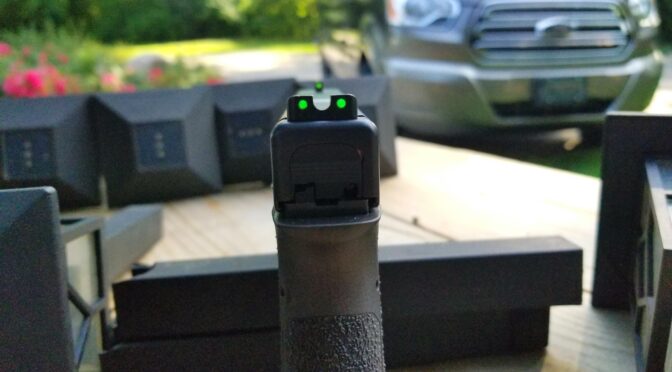
A fellow emailed me wanting to upgrade his from the generic OEM Glock sights that I don’t think really excite anyone to something that would be more visible in general and also work in the dark. My answer was immediate – go with the TRUGLO TFX Pro Tritium and Fiber Optic Xtreme sights.
The featured photo above shows how bright they are on my G17 slide on it. I bought these sights by the way – so you are getting my honest opinion.
Folks, these are my hands down favorite sights for a number of reasons:
They are CNC machined from steel and have a durable black nitride finish — they are not soft plastic.
They do not need batteries – the lit dots are via fiber optics when there is light and sealed tritium when it is dark so you are covered regardless of the light available. The tritium ought to fluoresce (emit light) for about 10-20 years and I’ll worry about replacing them then.
I really like the three green dot configuration – two on the rear sight and one on the front. The front also has an orange ring that you can see when there is light but is green when operating off the tritium only.
The rear sight goes into the slide’s groove very easily and is then secured with a set screw. Some sights can be a bear to install but not these.
The rear sight is big enough that it can help you rack the slide one handed in a one-handed emergency.
They have a 12 year warranty.
They are assembled in the USA – the tritium capsules are made in Switzerland.
What Glock models are supported?
Because these are so popular TRUGLO is making a variety of models to support the different Glock configurations that are out there. I assembled the following table and you can also check their webpage if you want:
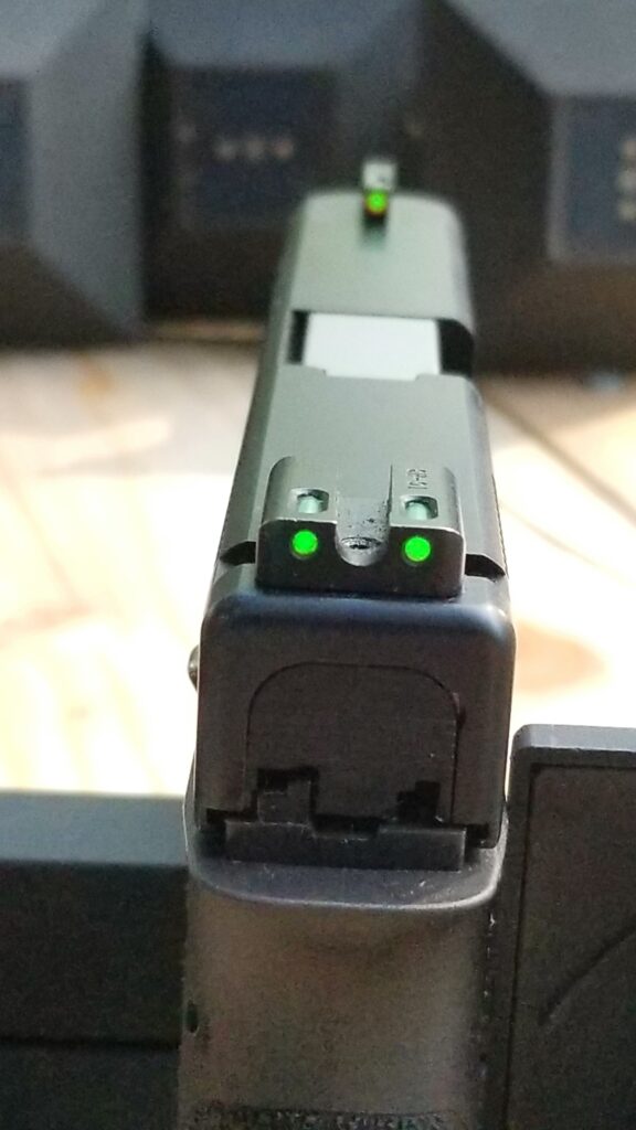
This gives you a better view of the sights overall. This is the TFX Pro TG13GL1PC with the fixed rear sight. I really like the sight picture these give day or night.
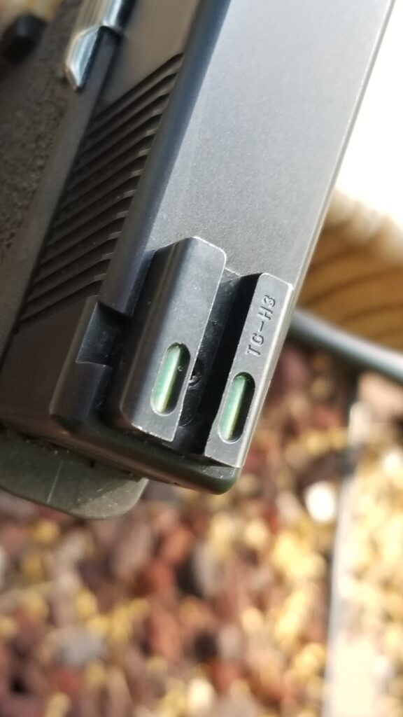
Here’s the rear sight and you can just barely see the set screw that secures the sight between the two “ears”. The slot at the top of each fiber optic is where it collects light to illuminate the dot. If there isn’t any light then that is where the tritium capsules take over.
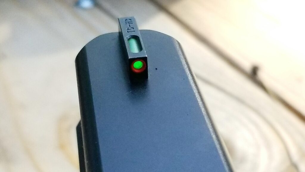
Here’s the front sight. The orange ring is nice during the day and you only see the green tritium dot in the dark.
Well, trying to take a photo in the dark of three green dots with a cell phone camera was an experience. I went in a basement room and shut the door to cut off light. It’s fuzzy but you get the idea – all three dots are nicely lit in any lighting condition.
Do they have lower cost models also?
Yes, they do. The Tritium series just has the tritium for illumination in the dark and show as bright white dots during the day.
They also make a Tritium Pro series that builds on the Tritium base model and adds an orange ring to the front sight plus the back sight is bigger and that makes it easier if you need to rack the slide with one hand.
I find these sights to be an incredible improvement over the plain Glock sights – they are easy to see and aid with rapid aiming. I really do like these sights and use them personally. I strongly recommend them.
I hope this helps you out.
Note, I have to buy all of my parts – nothing here was paid for by sponsors, etc. I do make a small amount if you click on an ad and buy something but that is it. You’re getting my real opinion on stuff.
If you find this post useful, please share the link on Facebook, with your friends, etc. Your support is much appreciated and if you have any feedback, please email me at in**@*********ps.com. Please note that for links to other websites, I may be paid via an affiliate program such as Avantlink, Impact, Amazon and eBay.
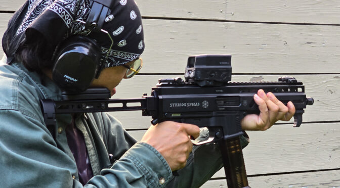
I posted about the modifications to the SP10A3 as well as magazine loaders and now it is time to talk about how it performed. One of my brother-in-laws and nephews were in town and ready to help me try it out. First off, we had a lot of fun and second, the 10mm Stribog ran stunningly well.
Preparing For the Range
When the Stribog arrived, I field stripped, cleaned and lubricated it. This is always a good idea because you never know what all will be in a firearm – preservatives, dirt or even dry with no lubricant.
The manual is well written so read it. The sections on field stripping, cleaning, and oiling are worth your time. I would also recommend hand cycling the action a few hundred times to accelerate your parts getting to know each other – also known as wearing in.
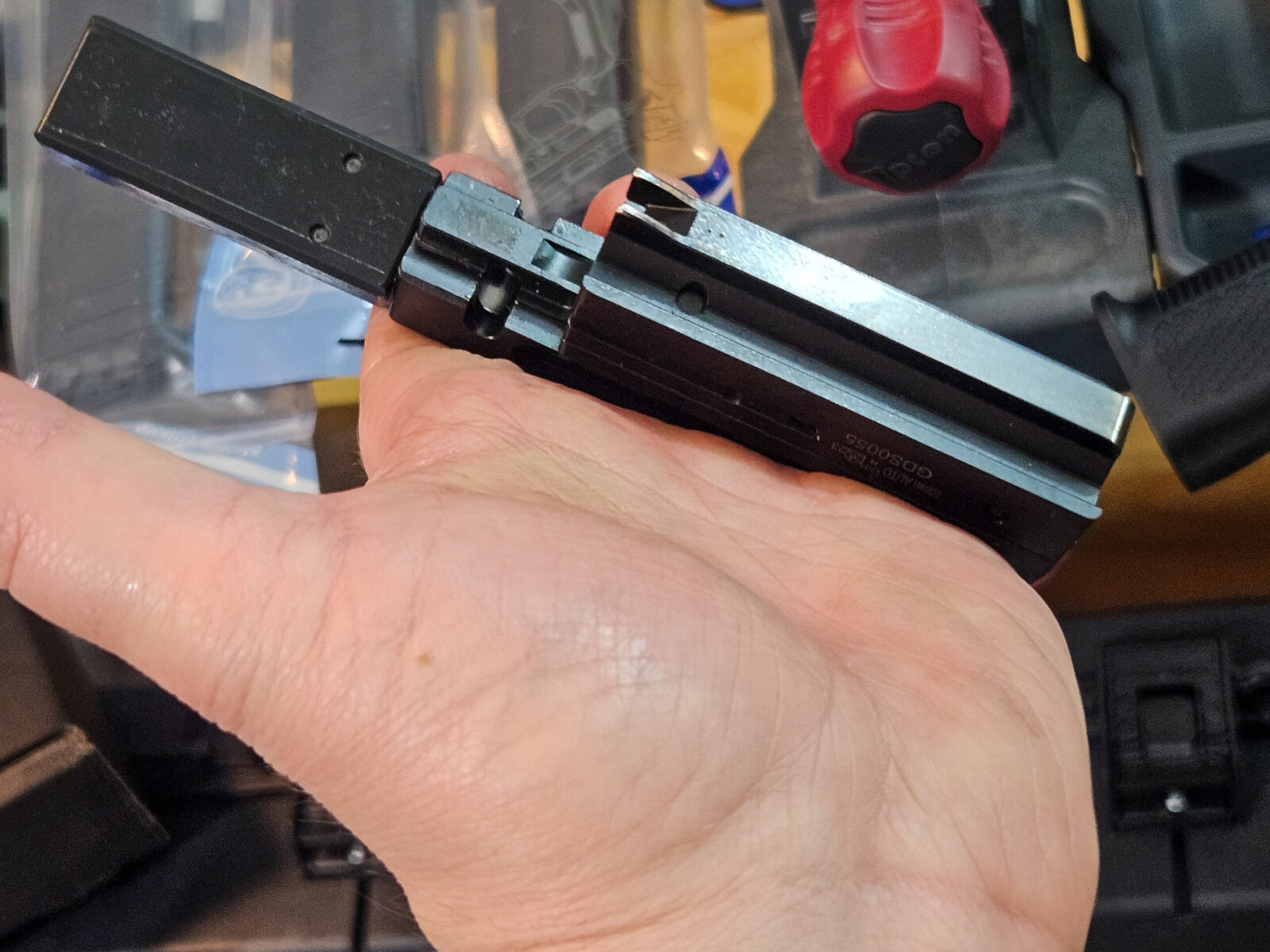
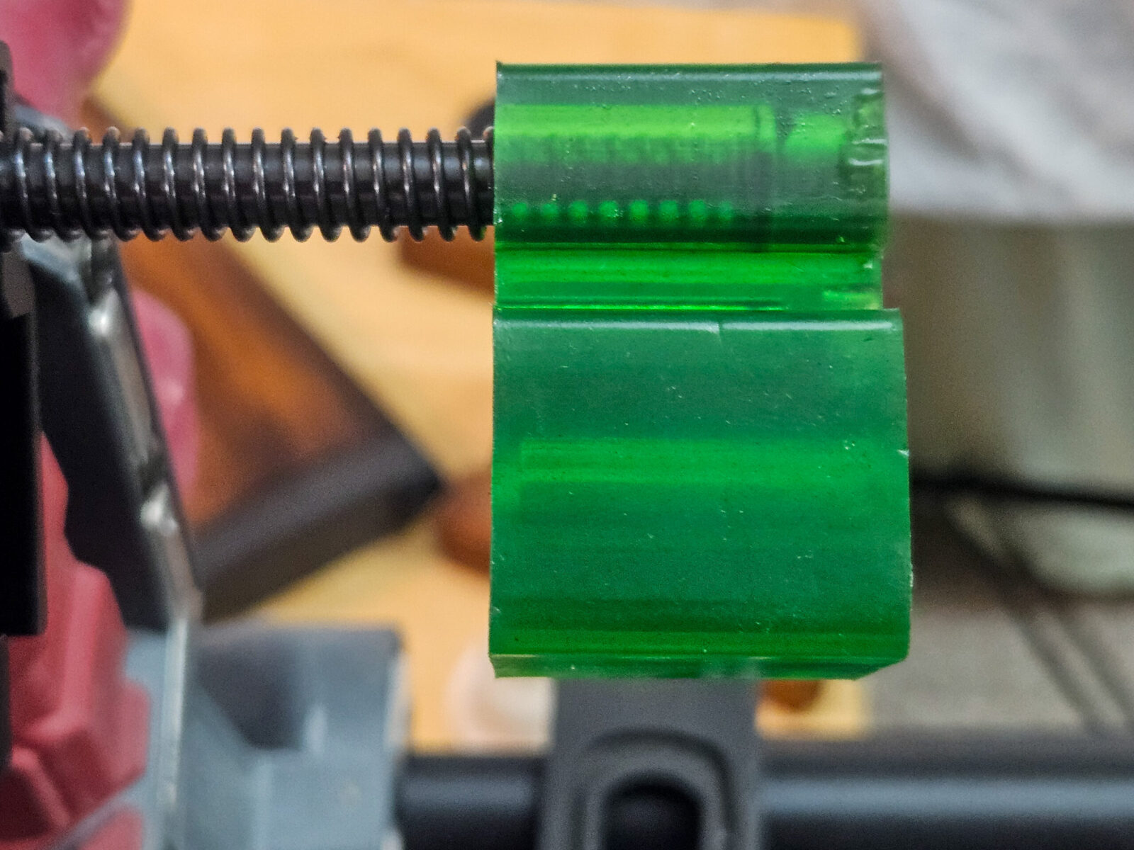
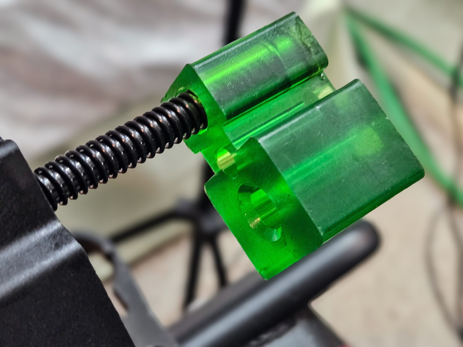
The bolt assembly made up of the large carrier to the rear (right) and the bolt head in front (left), is enormous. A lot of the 10mm recoil is eaten up by inertia, the recoil spring and then a giant buffer block. It’s no wonder the recoil is incredibly mild. Also, when you have something this big, there can be a ton of friction so you need to lubricate it.This giant rubbery green thing is the recoil buffer. I honestly don’t recall ever seeing one this big – every. If the inertia of the bolt and recoil spring leave enough energy to drive the bolt carrier into this buffer, it can handle it without a doubt.
Visiting the Range
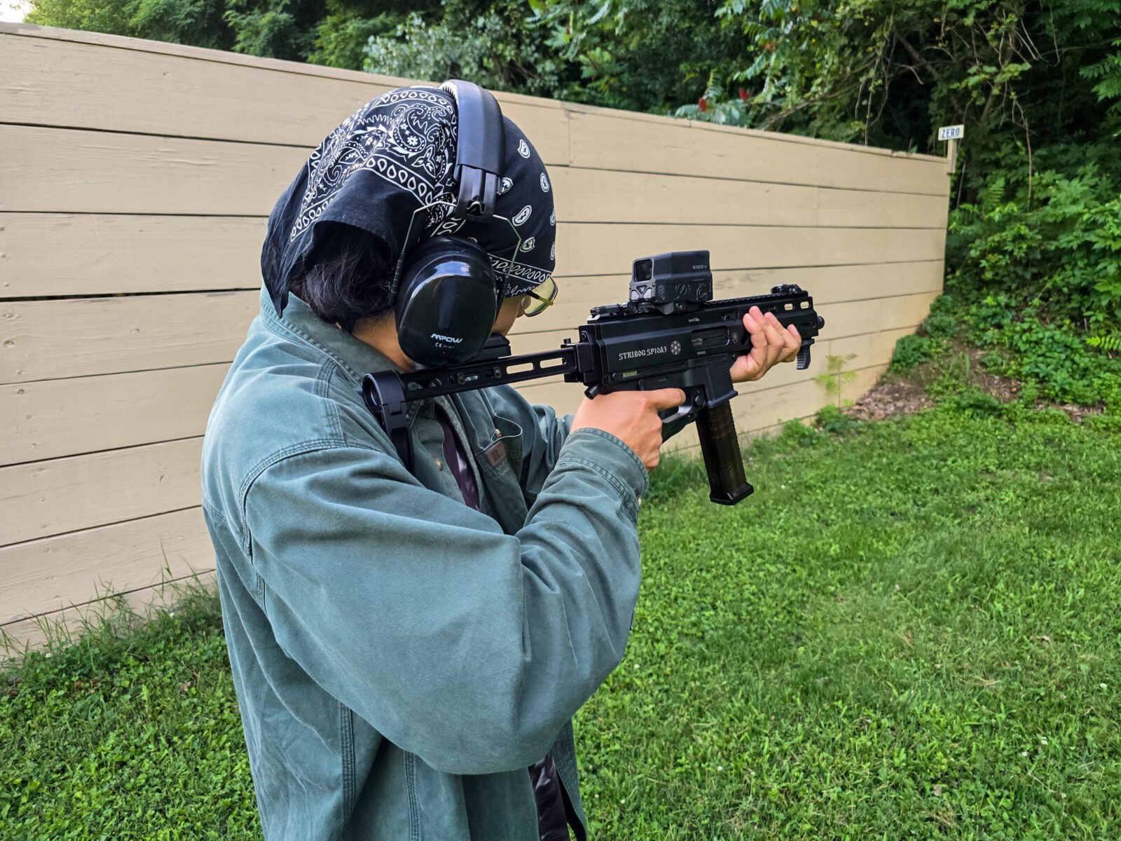
My brother-in-law, Banduy, and nephew, Julian, headed to the range to have some fun and break in the Stribog. It was a great day as we unloaded and set up the targets, moved the bench into place and got ready.
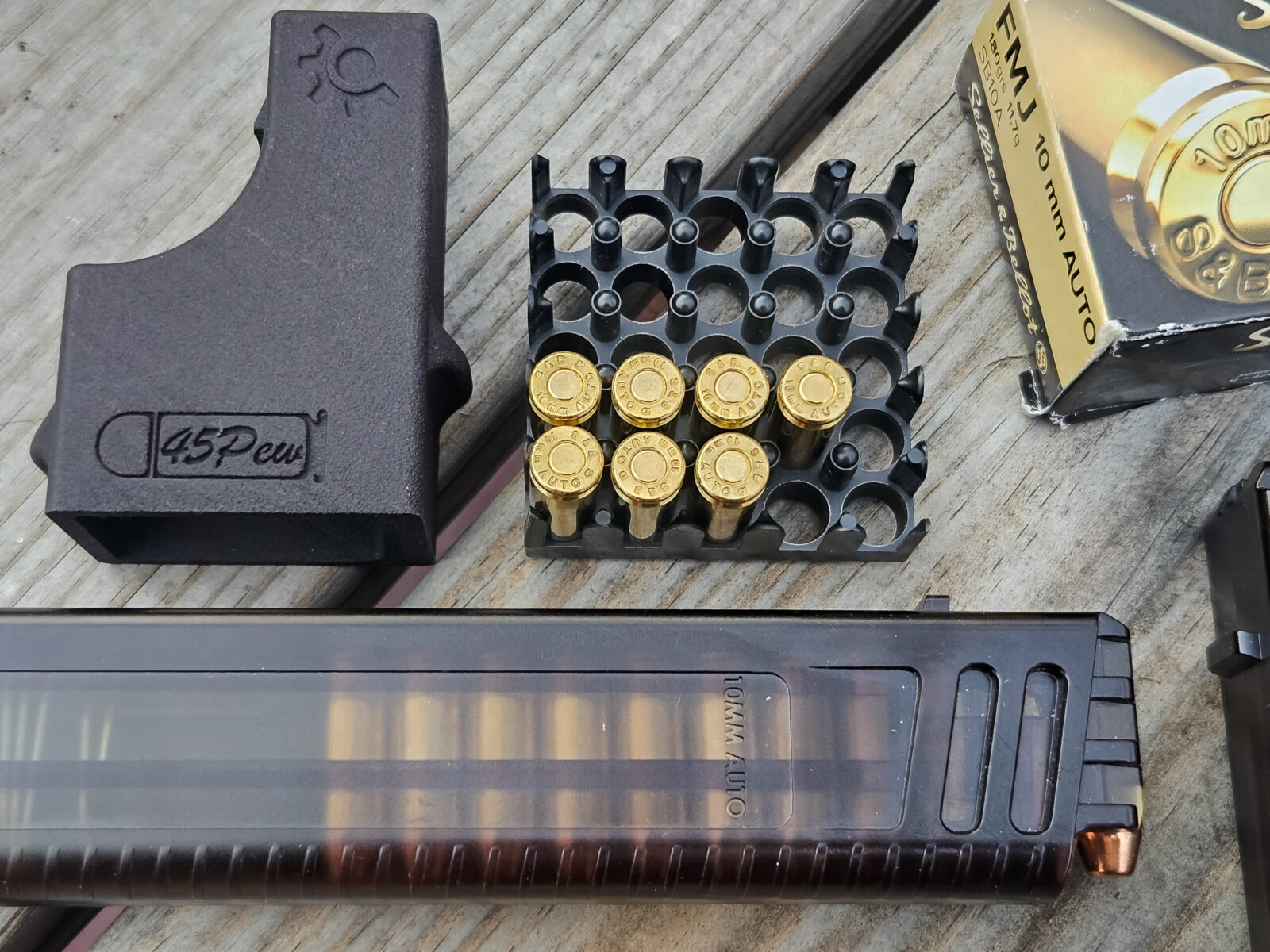
We used the Custom Smith .45 UMP loader to fill up four 20 round magazines with S&B 180gr FMJ. Folks, I have shot cases of this stuff and it’s fantastic range ammo in all of my 10mm pistols and now the Stribog.
I shot the first magazine and was very impressed. The action was smooth with very little felt recoil. I did need to dial in the UH-1 a bit as the laser boresight allowed me to get the UH-1 in the vacinity if the round impacts on the paper.
By the way, I initially had a quick connect sling loop on the A3 Stribog adapter just about the top rear of the grip. It was really annoying and I got rid of it very quickly. Maybe someone with smaller hands wouldn’t notice it but I sure did.
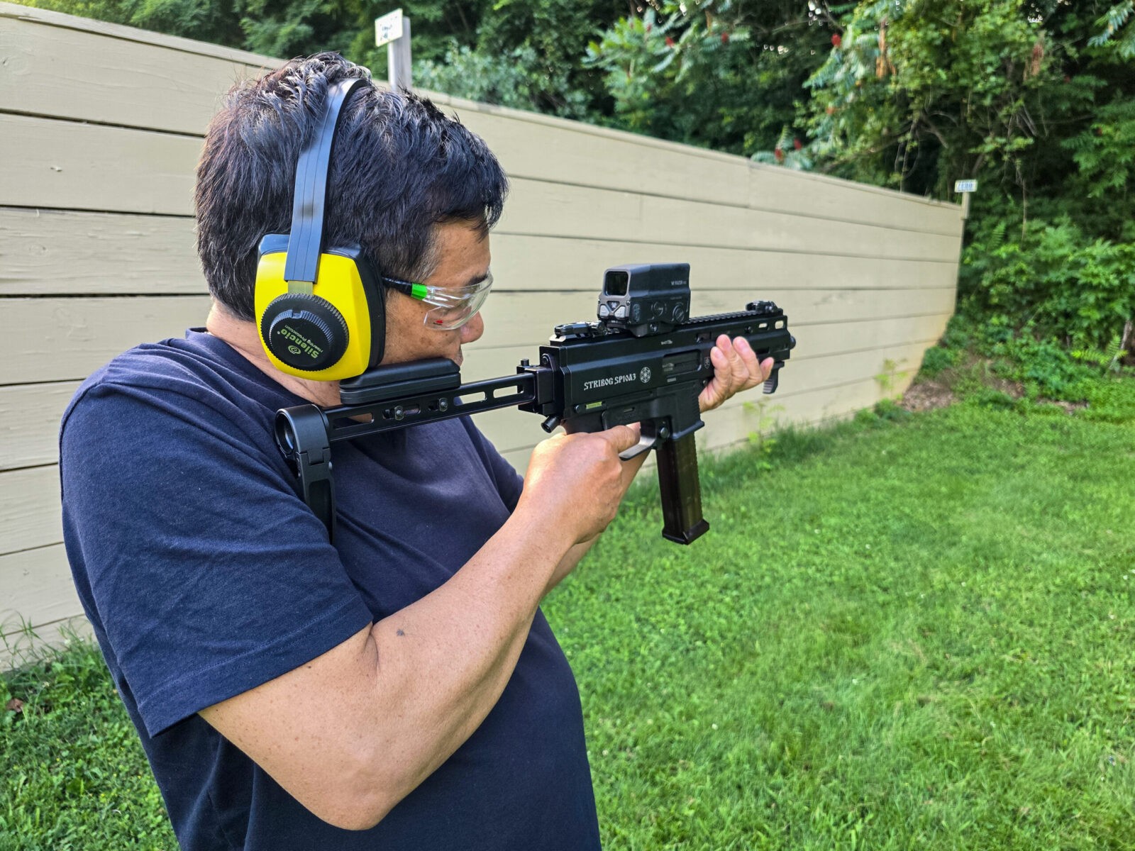
Julian has been shooting with me for almost 20 years now. Time flies by. He was next up and with practiced skill did a steady 20 round set standing freehand with no problems at all.This was his first 20 round set as he got used to the Stribog. He was about 25-40 feet back getting started.His dad was up next and did a good run. I haven’t done a comparison of felt recoil with the micro compensator and without. I can tell you that it is incredibly smooth with it on.We had a lot of fun. The Stribog just rocked it, No failures of any kind through 200 rounds of ammo. The one thing I realized after the outing was that I could shoot through a case of 10mm pretty quick with the SP10A3.
Summary
We shot the Strbog freehand back to about 25 yards and found it to be a delight to shoot. It definitely filled my desire for a 10mm carbine vs. my various 10mm pistols and would highly recommend it. GrandPower did another great job with the SP10A3.
I’ve since had it out a couple of more times and it’s run great everytime. Yes, I did have to buy more S&B 180gr ammo because of it 🙂
I hope this helps you out.
Note, I have to buy all of my parts – nothing here was paid for by sponsors, etc. I do make a small amount if you click on an ad and buy something but that is it. You’re getting my real opinion on stuff.
If you find this post useful, please share the link on Facebook, with your friends, etc. Your support is much appreciated and if you have any feedback, please email me at in**@*********ps.com. Please note that for links to other websites, I may be paid via an affiliate program such as Avantlink, Impact, Amazon and eBay.
Back in 2022, I bought a Stribog SP9A1 and really liked it. Then the ATF brace fiasco rolled around and I decided to sell it. It was a darned nice 9mm pistol caliber carbine (PCC) with the brace and I have since regretted selling it. Once the brace ruling was shot down, it went back on my “I need to get another one some day list”. Before I decided to buy te SP9A3, Grand Power decided to release a 10mm version – the SP10A3. Two weeks later I had one.
Why did I jump on the 10mm? In general, I like to let new designs settle down and get the bugs worked out. In this case, Grand Power was taking a very proven design and upscaling it. The second reason is that 10mm is God’s Pistol Cartridge in my mind. Sure, the 9mm has thousands of loads and can do the job but 10mm was designed by Colonel Cooper to fill a gap he saw for pistols reaching out to 50 yards. It was souped up from the get go.
At any rate, I have a number of 10mm pistols right now, have always liked the 10mm round including for back woods bear defense. I wasn’t adding a caliber but extending the situations wherein I could use it. I’m honestly not accurate with a pistol beyond 25 yards due to my tremor and have wanted a 10mm pistol caliber carbine (PCC) for quite some time. I have always been far more accurate with a carbine than a rifle. The problem has always been a lack of affordable 10mm PCC options on the market. So, when I read the first blog post about a 10mm Stribog being released, I moved fast.
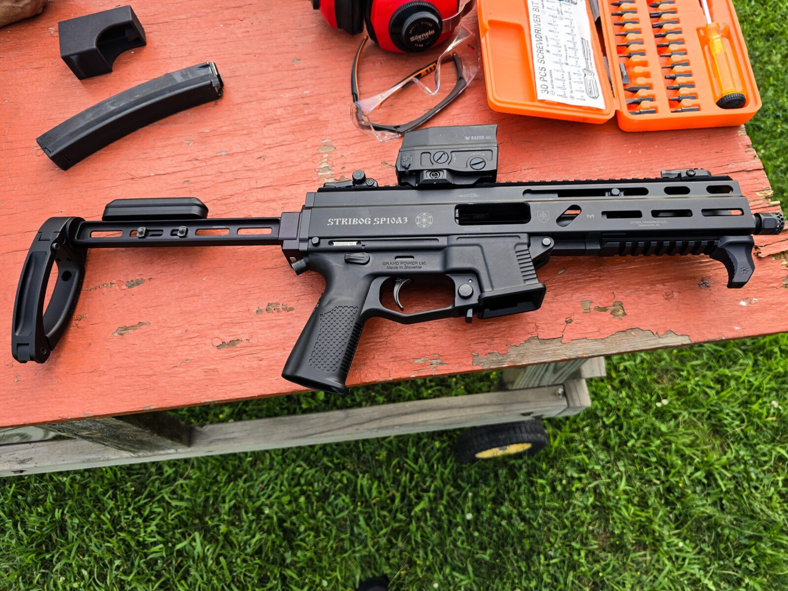
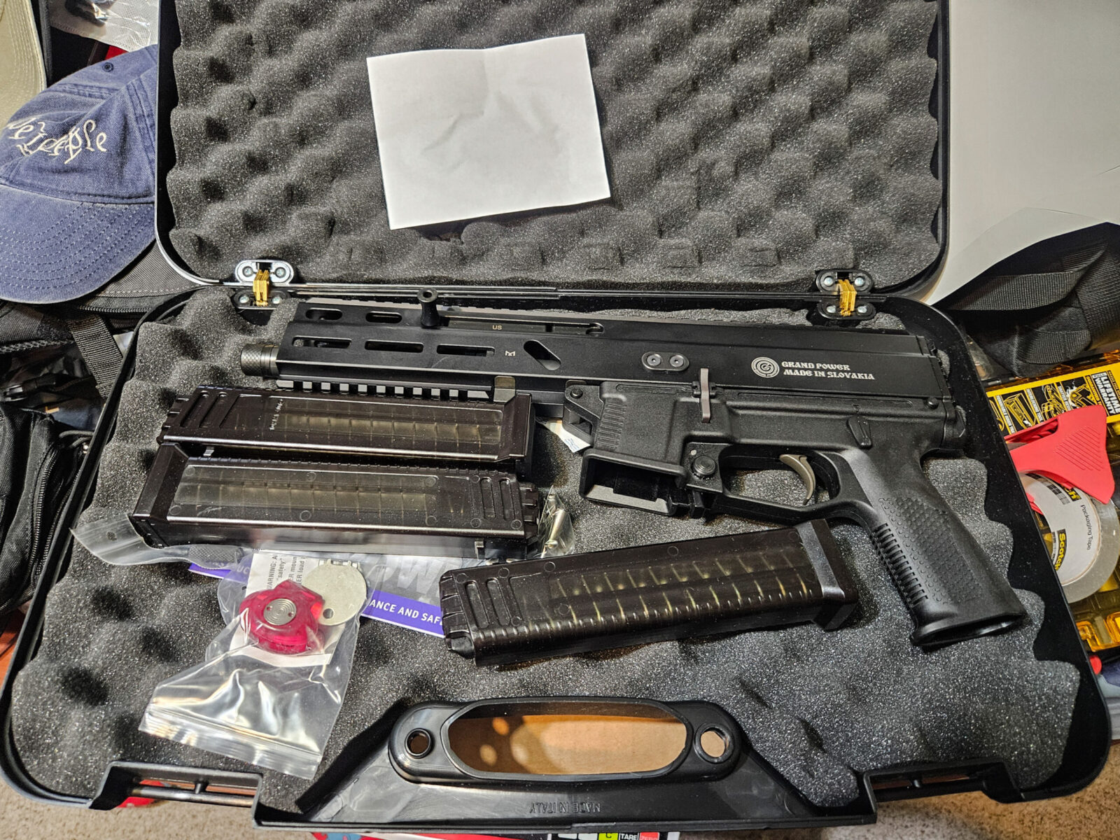
The Stribog SP10A3 showed up in a very nice hardcase with three of it’s magazines. It was time to get creative.
Making the Mods
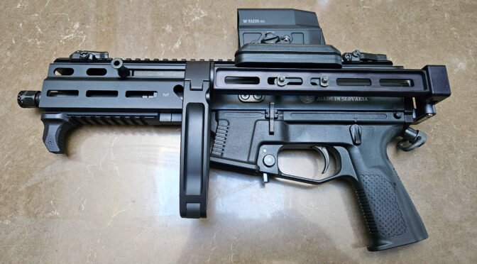
I knew the base Stribog SP10A3 would be too heavy for me to shoot as a pistol so I started researching what all I was going to do in terms of the brace, compensator, optic and handstop.
The Brace
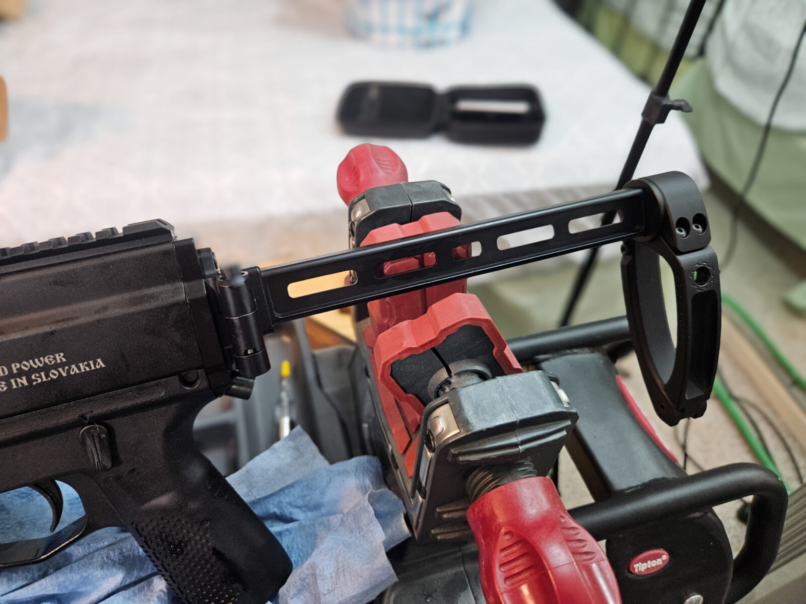
For the brace, my first choice was the F5 modular brace but they were sold out because they really hadn’t kicked back into gear after the brace ruling was repealed. I knew I wanted a folder so I went with an A3 Tactical Modular Folding Brace – which has adapter, folder and aluminum struts. For the actual brace portion, I like the aluminum Tailhook Mod 1 braces – they have great machining and don’t flex at all. I also opted for a Xeno cheekpiece that attaches to the strut.
By the way, the SP10A3 can use the same braces as the SP9A1 and SP9A3 series weapons. It comes with a polymer rear cap that has an integral 1913 Picatinny rail on it so you can use one of the many options out there – notably the various options from JMAC Customs that pioneered the concept.
This is the A3 modular brace comprised of the Stribog adapter, folding mechanism, straight aluminum strut and a Mod 1 Tailhook brace. Note, The SP10A3 uses the same braces as the SP9A1 and A3.This is a close up of the Tailhook Mod 1 brace. You push a button on the other side and it opens up to provide support under your arm for more stable one-handed shooting.
The Compensator
Now this part might have been overkill. The Stribog SP10A3 is a chunky boy but not in a bad way. I expected it to manage the 10mm cartridge’s recoil just fine all on its own but it had a 9/16-24 threaded barrel that needed something stuck on it! Take that thread size and a 10mm/.40 S&W caliber and you enter the land of limited choices. Hint – search for the .40 and you’ll get more results.
First, I detest aluminum muzzle brakes. When you shoot a lot, the erode quickly due to the heat and particles of the muzzle blast. I’ve also seen aluminum brakes and fake cans droop/sag when the aluminum gets so hot it starts to melt. So, I wanted steel.
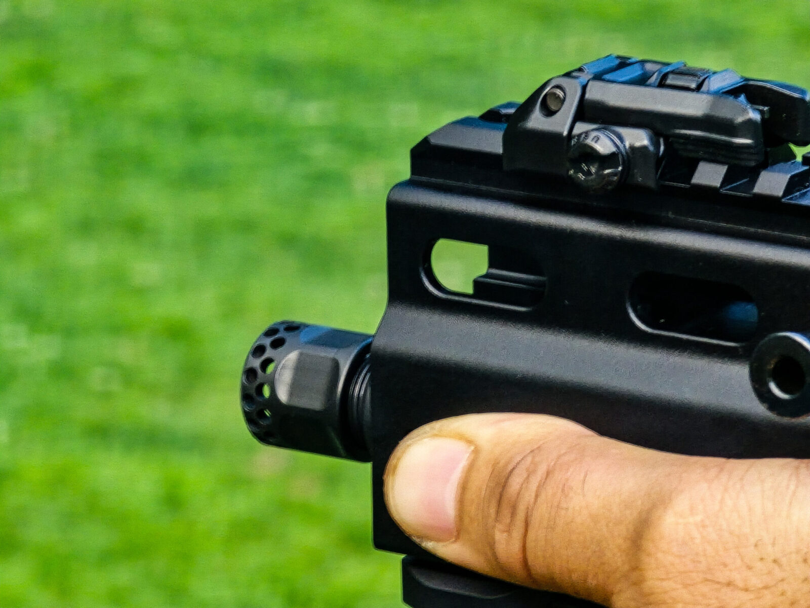
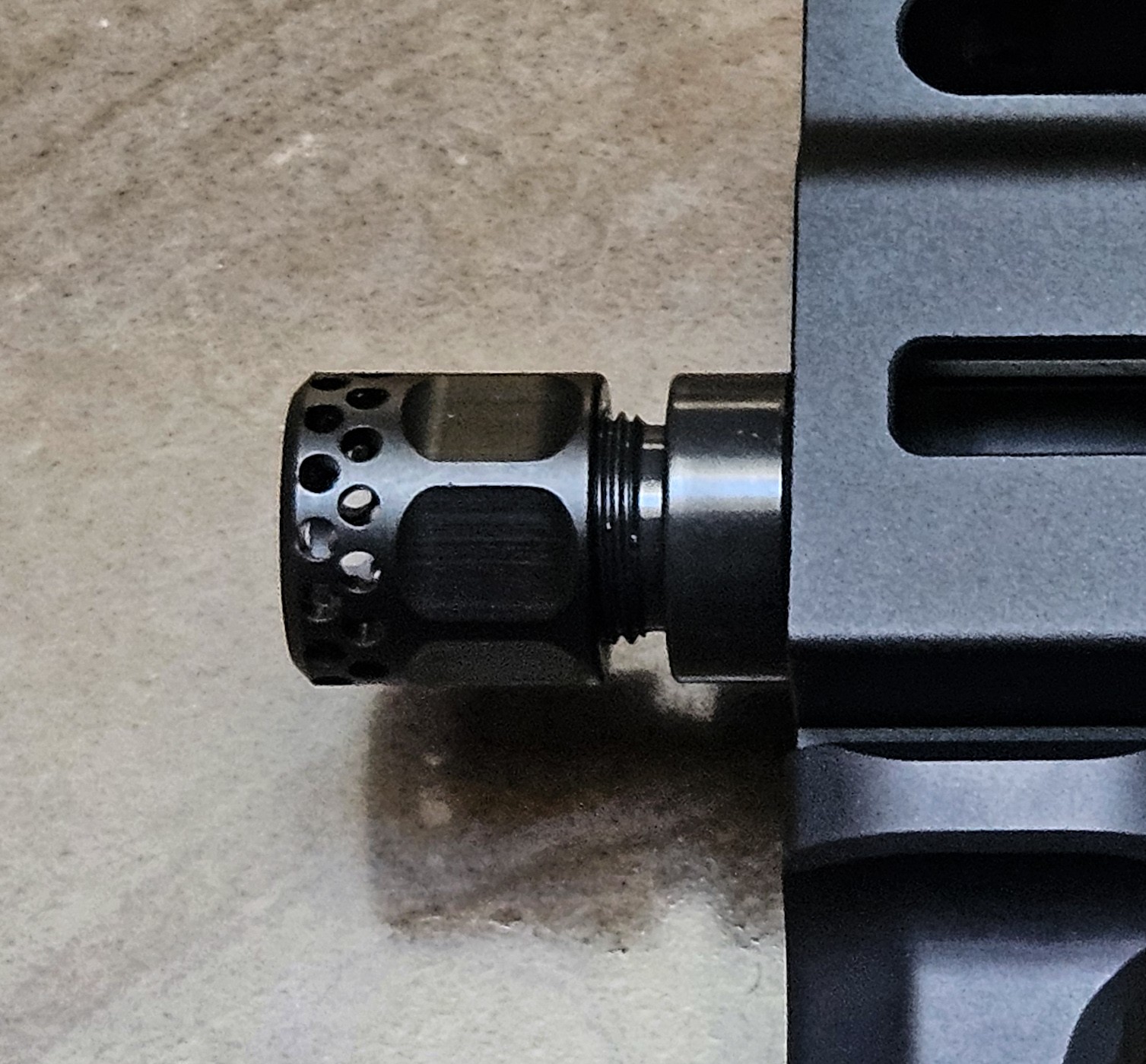
After some digging, I went with an HK Parts Micro Comp. It’s ordnance grade steel, nitride finished, very small and they have two models – one with slotted ports and one with numerous circular port holes. I went with the latter just because I’ve used the circular port style in the past with good luck.
That huge green chunk of rubber is the recoil buffer of the Stribog SP10A3. As I wrote this, I was trying to think of all the SciFi movies that had some substance made up of this green color. Well, I’ll let you ponder that but I can tell you it does the job of soaking uip some of the remaining recoil remarkably well.This is the HK Parts Micro Comp – 9/16-24 for .40 caliber.
The Optic and BUIS
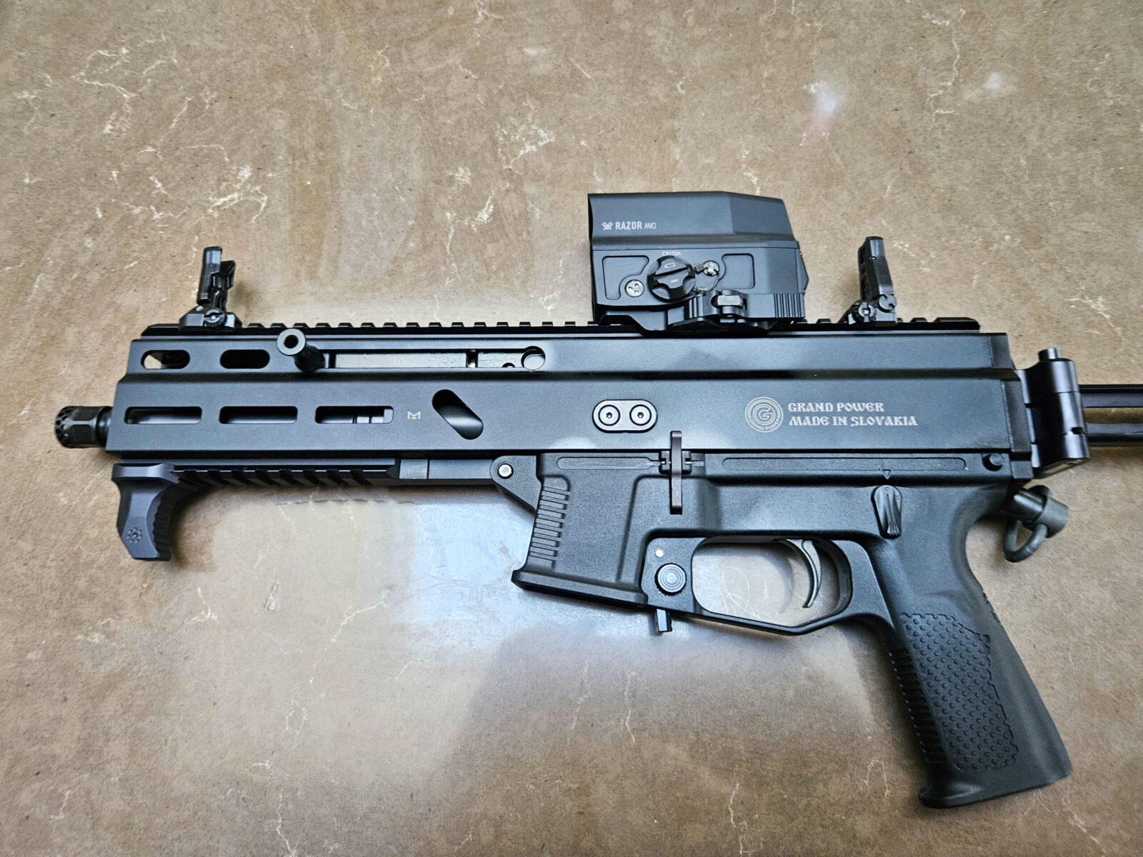
I wanted a fast optic sight for target acquisition within 100 yards. The Vortex AMG UH-1 is a perfect fit for this situation. Being a holographic sight, it is parallax free, has unlimited eye relief and appears to the eye as being on the same plane as the target. Moreover, the laser projected EBR-CQB reticle has a one minute of angle (MOA) red dot surrounded by a 65 MOA target acquisition ring.
People ask me why I am so pro-Vortex and the reasoning is simple – the optics have excellent engineering, work as claimed, are very durable and are backed up by a no-hassle warranty. To save money, I could have opted for the Vortex Crossfire red dot but the UH-1 is such a step up with its bigger window and reticle that I went with it.
By the way, unless a weapon will only be used at ranges, always factor in backup iron sights (BUIS). In the case of pairing BUIS with the UH-1, I used Magpul Pro Sights. The Pro series sights are made from steel vs. their polymer counterparts and I have slowly drifted towards them over the years because I find them robust and reliable.
Here is the Vortex AMG UH-1 optic and the front and rear Magpul Pro Sights. I tend to run the BUIS folded down until I need them. They are in the deployed/up position right now for the photo.
The Handdguard and Handstop
One design difference that I appreciate is that the SP10A3 has a long handguard right out of the box. With the SP9 series you either had a lot of barrel exposed or you added something like the Dragon Snout. So, no changes there.
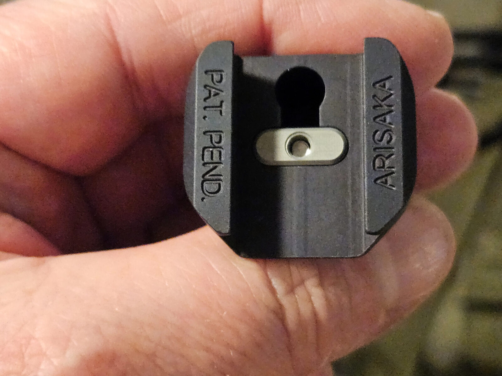
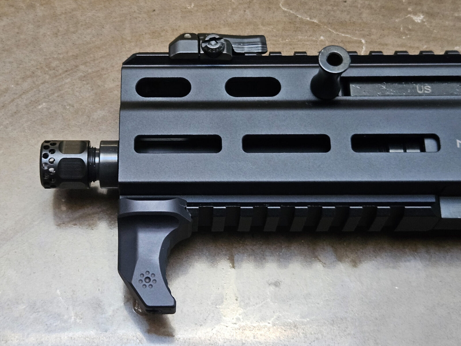
The one thing I did add was an Arisaka HS-P hand stop. Call me paranoid but I want something at the end of the handguard that stops my hand from sliding off the end. The Arisaka is a simple rugged hand stop that has a really novel way of locking itself onto your Picatinny rail vs. unsightly exposed screws.
You slide the HS-P on your rail to the location you want. You then use a hex head wrench to deploy the silver lug shown above between the elevated Picatinny segments and it locks in place. It’s such an elegant design and rock solid.Here is a photo of the Arisaka HS-P in position. It works great and feels great — I seriously like this little hand stop!
I Haven’t Changed The Trigger Yet
One thing I did notice was the trigger. The SP9A1 Stribog I owned had a surprisingly good trigger. What was in my SP10A3 was a “meh” trigger. Not great but not horrible either. Guess what? It turns out it is an AR fire control group. You can go to whatever AR trigger you want although I am doubtful cartridge triggers will work. I may change it out for a Geiselle in the future or even just polish it but left it alone for now.
I was surprised to find out from Grand Power USA that the Stribog SP10A3 uses an AR fire control group. I never asked about my SP9A1 because it was remarkably decent straight from the factory. Looking at the finish on the hammer, it could use some polishing or just to get worn in — in other words, shoot it a bunch, let the parts get to know each other ane a lot of the roughness will smooth itself out as imperfections get worn down.
End Result
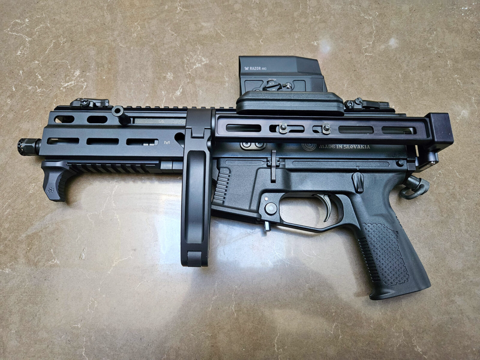
The Stribog turned out slick. The only thing I have ditched so far is the quick disconnect sling swivel you see just above the pitol grip. While it seemed like a great idea, it annoyingly interefered with the web of my hand between my thumb and index finger.
Summary
I was genuinely excited. The SP9A1 I had impressed me so much that I ordered this SP10A3, planned and installed some modifications. Next up was to take it to the range and just to spoil the next post a bit – it ran stunningly well with S&B 180gr 10mm FMJ ammo.
Note, I have to buy all of my parts – nothing here was paid for by sponsors, etc. I do make a small amount if you click on an ad and buy something but that is it. You’re getting my real opinion on stuff.
If you find this post useful, please share the link on Facebook, with your friends, etc. Your support is much appreciated and if you have any feedback, please email me at in**@*********ps.com. Please note that for links to other websites, I may be paid via an affiliate program such as Avantlink, Impact, Amazon and eBay.
The short answer to that question is “No” but then when someone asks if they can use some Picatinny mount on a Weaver rail it becomes “It depends”. Why is that?
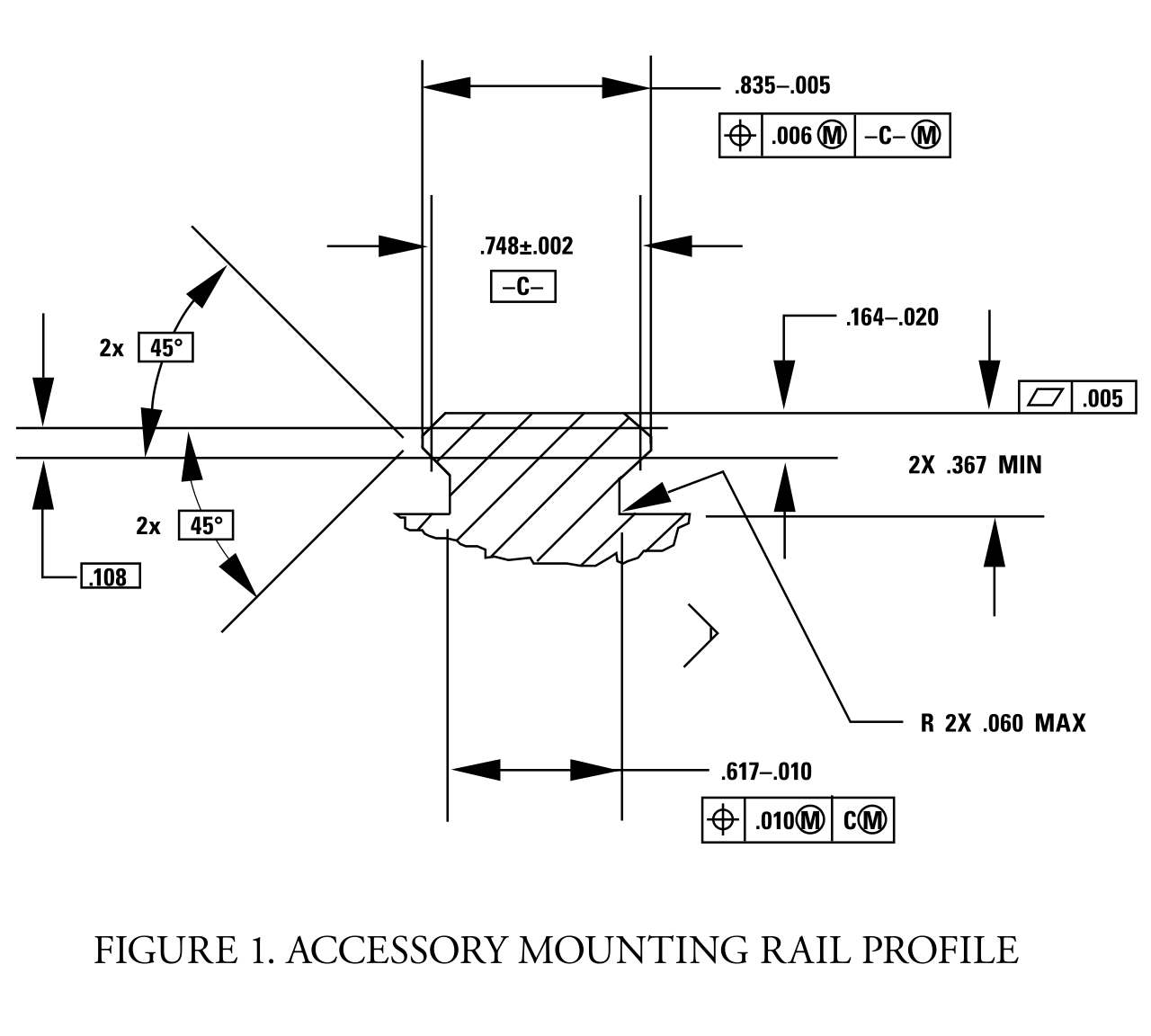
Well, the Picatinny rail does have a true military specification – “MIL-STD-1913″ that lays out the details but nothing like that exists for Weaver rails – when writing this post, I did some digging and I can’t find an authoritative width of the rail, the recoil slot is about 0.180” but their spacing, number and depth can all vary.
The reason that Weaver rings and mounts can typically fit a Picatinny rail is that the recoil slots are 0.206″ wild and spaced 0.394″ apart. However, if you are using rings that were on a Weaver rail, while the bolts or recoil bars may fit the Picatinny slots, the spacing between the mounts may need to be adjusted.
There are plenty of posts out there with more details but I would tell you to only use Picatinny rails and mounts going forward if at all possible. The reason is that because there is the published MIL-STD-1913 specification, the interoperability of parts from different vendors is far, far more likely.
I was unable to find a US DOD direct link for the MIL-STD-1913 but I did find two sites hosting scanned copies – BiggerHammer and EverySpec
Some Photos
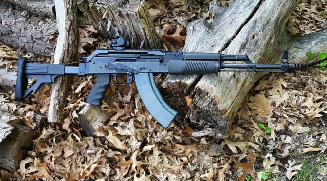
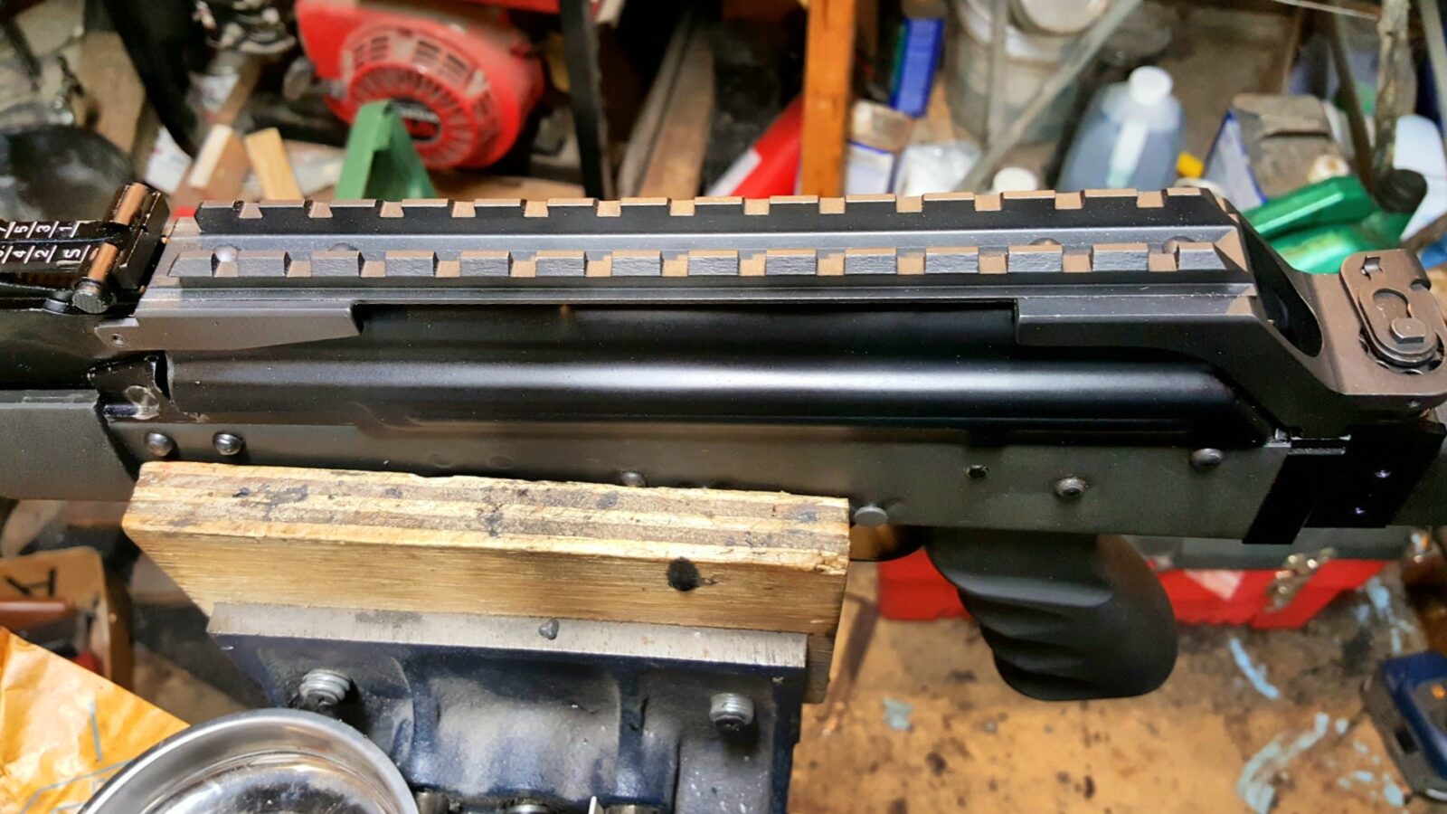
What inspired me to sit down and write this is my working on a 5.56 Polish Beryl right now. The actual Beryl optics rails are a both rare and cost a fortune. While there are Picatinny versions out there, I have two of the older Weaver rail design they started with and am lucky that my ADM and Vortex mounts all surprisingly fit – it’s always nice when things work out in a good way.
At first glance, you’d think it was a Picatinny rail with the slots going the whole length. It’s actually a Weaver rail. Weaver rails can have dramatically different numbers of slots and spacing.
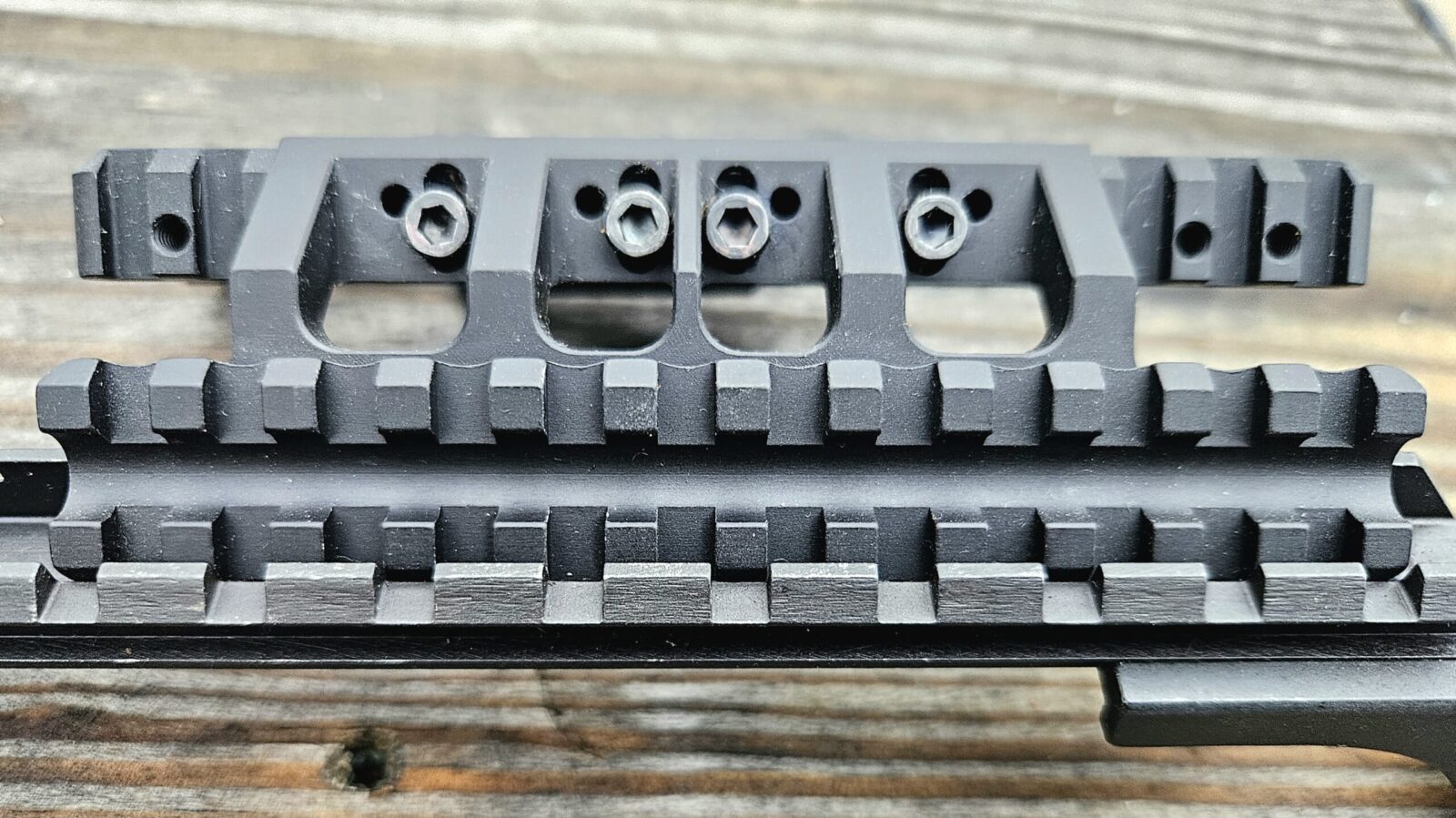
The top is a RS Regulate Picatinny rail. The bottom is the Beryl’s Weaver rail. You can see the difference in the recoil slot spacing. By the way, RS Regulate is my favorite AK scope mount hands down.
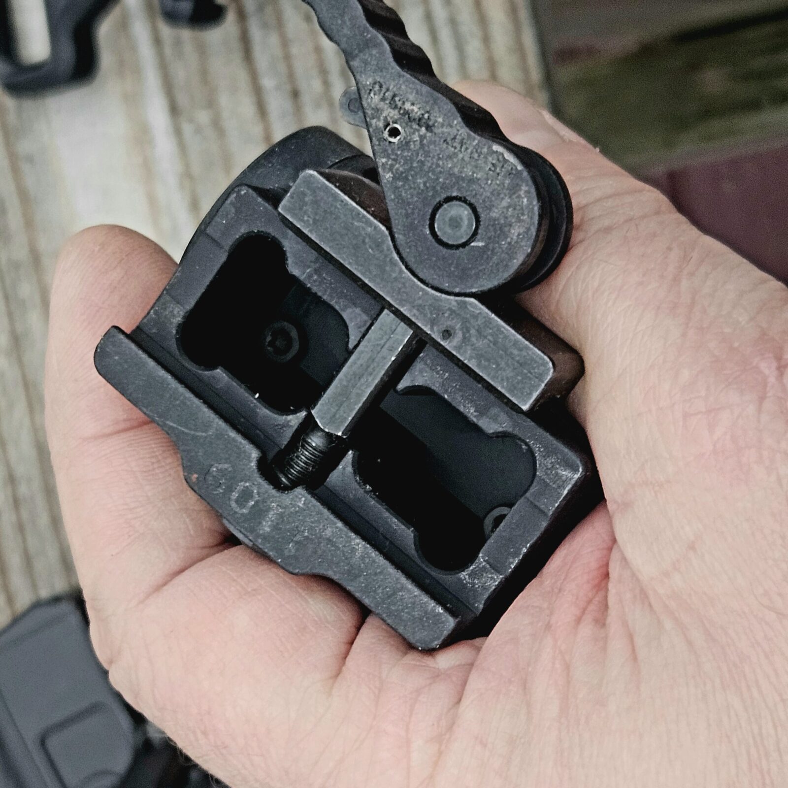
That is the bottom side of an American Defense Manufacturing (ADM) mount and my goto scope mounts these days when I want quick connect levers. The recoil bar is what may or may not fit a Weaver rail. Now this only has one lever and bar – One piece scope mounts will likely have two recoil bars and the spacing between them could compound fitting challlenges.
The Vortex UH-1 and Crossfire red dot on an ADM base both fit the Beryl rail.
In Closing
Weaver and Picatinny rails are different. In general, you can use Weaver mounts on a Picatinny rail but you may not be able to put a Picatinny mount on a Weaver Rail.
In my case, I got lucky and could mount the red dots no problem. A mount with two screws/contact points may or may not line up – that will just depend on many factors in terms of the spacing between the recoil bars, size of the bars, etc.
Bottom line, go with Picatinny rails and mounts going forward to maximize your ability to move components around.
Note, I have to buy all of my parts – nothing here was paid for by sponsors, etc. I do make a small amount if you click on an ad and buy something but that is it. You’re getting my real opinion on stuff.
If you find this post useful, please share the link on Facebook, with your friends, etc. Your support is much appreciated and if you have any feedback, please email me at in**@*********ps.com. Please note that for links to other websites, I may be paid via an affiliate program such as Avantlink, Impact, Amazon and eBay.
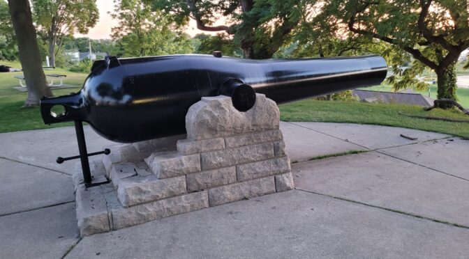
In Saint Joseph, MI, near the intersection of Lake and Broad Streets sits a civili war monument consisting of an Eleven Inch Dahlgren and some stacked shot. The gun is pointing out to the lake and there is a simple sign for curious folks to read.
I’ve read this sign and looked at the cannon many times over the years and realized it was time to write a post about it.
Photo Gallery
The following is a gallery of photos of the 11-inch (XI) Dahlgren. If you clck on one, then you can see it full size and navigate around:
Some History
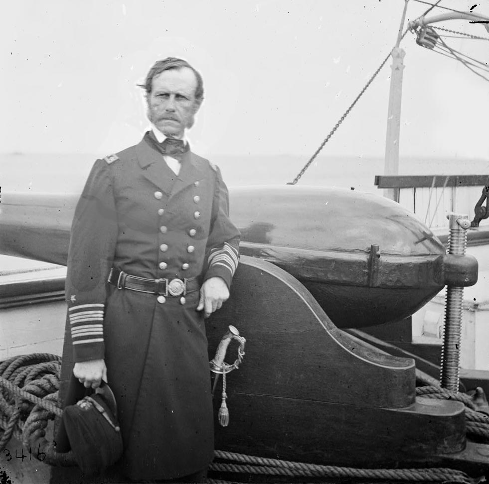
St. Joseph’s 11-inch Dahlgren gun was built in 1864 at Hinkley, Williams & Co. in Boston, Massachusetts, for service in the Civil War. It and other guns of its type were designed by Rear Admiral John A. Dahlgren who wanted to use more more modern design methods to create a safer and more powerful gun. His designs were known as “Soda Bottles” because of their characteristic rounded shapes with additional steel at the rear to strengthen the breach.
Rear Admiral John A Dahlgren – the designer of the Dahlgren guns (Source: Wikipedia)
In total, 465 of the XI (Eleven) inch guns were made at five different foundaries between 1856-1864. That means the Saint Joseph gun was built during the last production year.
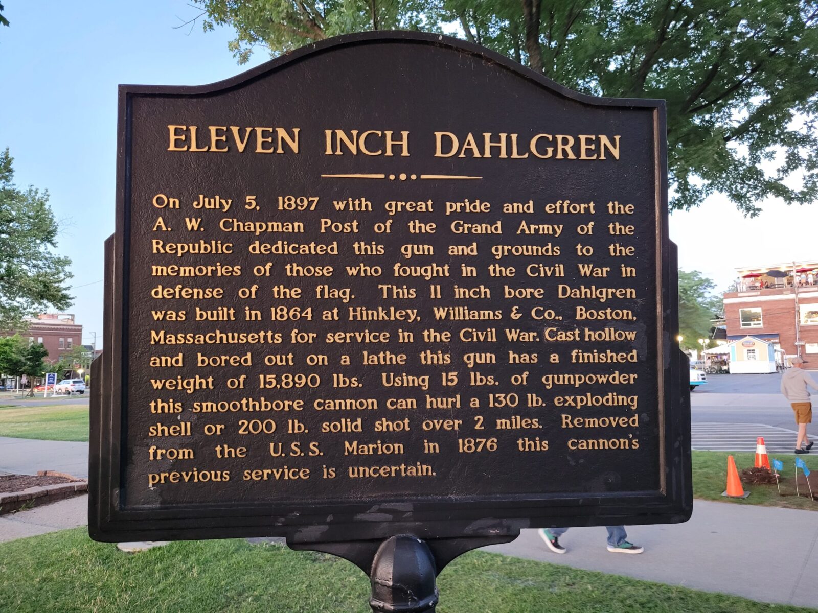
The smoothbore gun was cast hollow, bored out and lathed to a finished weight of 15,890 pounds which is marked on the gun. The sign and the reference table from Wikipedia are close but not exact:
The sign says the gun used a 15 pound charge and could hurdle either a 130 pound exploding shell or 200 pound solid shot a distance of over two miles.
Wikipedia cites a reference book on Civil war artillery that the gun used a 20 pound charge to launch either a 133.5 pound exploding shell or 166 pound solid shot a distance of 3,650 yards (2.07 miles) at a 15 degree elevation.
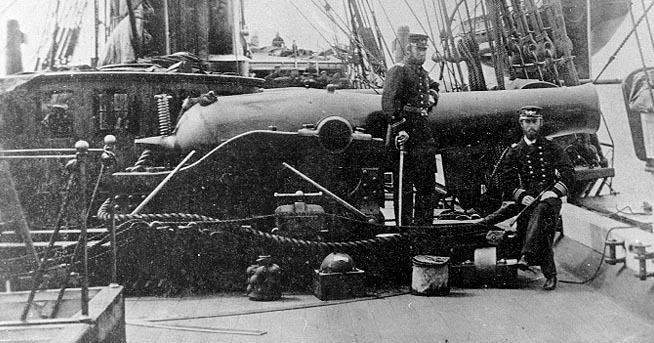
Here is an 11-inch Dahlgren mounted on a pivot mount. This is on the USS Kearsarge, a contemporary ship to the USS Marion that the Saint Joseph gun came from.
There is an interesting 12 year gap here. The gun was made in 1864 and the sign says it was removed from the USS Marion in 1876 and it’s previous use was uncertain. Was it on the Marion the whole time? Let’s try and look at that.
USS Marion
Drawing of the Marion at Hampton Roads circa 1880 (Source: Wikipedia)
From Wikipedia, here’s a quick timeline of the USS Marion:
April 24, 1839 – Launched as a sloop-of-war – 25 years before the St. Joseph gun was made in 1864
1856-1857 in ordinary – this means it was in a reserve fleet. It might have needed repairs or overhauling.
June 21, 1861 – recommissioned after the Civil War broke out
July 14, 1861 – set sail
May 1862 – ordered to Boston for repairs
July 24, 1862 – ordered to Annapolis for use as a practice ship until 1870
1864 – The St. Joseph gun was made in Boston (according to the sign)
1871 – Rebuilt as a third-class steamer
January 12, 1876 – Recommisioned
1876 – The gun was removed from the Marion (according to the sign in St. Joseph)
July 5, 1897 – gun dedicated in Saint Joseph – it had to travel there, be installed, etc. (according to the sign)
So, not much we can glean from what I can find. Odds are the 11-inch Dahlgren was getting dated by that time.
Summary
Today, kids climb around on the XI-Dahlgren gun and families take photos but they don’t know much about it. I suppose the Civil War is becoming just a few days, if even that, in history classes. Regardless, it is a memorial for men who served from the area. It’s well maintained by the city and gracefully stands guard looking out at the lake.
If you find this post useful, please share the link on Facebook, with your friends, etc. Your support is much appreciated and if you have any feedback, please email me at in**@*********ps.com. Please note that for links to other websites, I may be paid via an affiliate program such as Avantlink, Impact, Amazon and eBay.
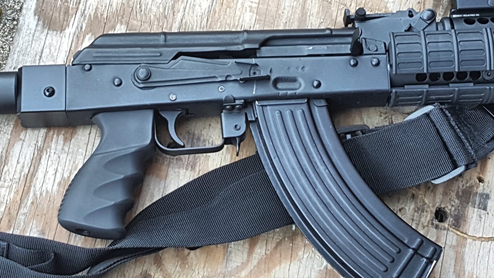
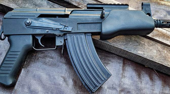
Some time back in 2017 or 2018, I bought some original Beryl second generation grips – the larger one with finger grip cut outs. I then made a couple of molds based on the originals. I thought they would be popular right away, but I’d sell one here and there and then Arms of America started importing Beryls with the AKM-looking grip. Guys started buying my grip and reports started coming back to me this year that my grip was loose on their Beryl rifles. This really confused me as my mold was cast from an original. At first I thought it was occasional issues with the customer or the rifle but then more reports came back and I had to dig in.
A customer, Phillip, sent me a ton of photos and links to posts of guys sharing how they fit my grips to their rifles. Whoa! I had no idea! Thanks to Phillip’s help, I was able to figure out what was going on and write this post.
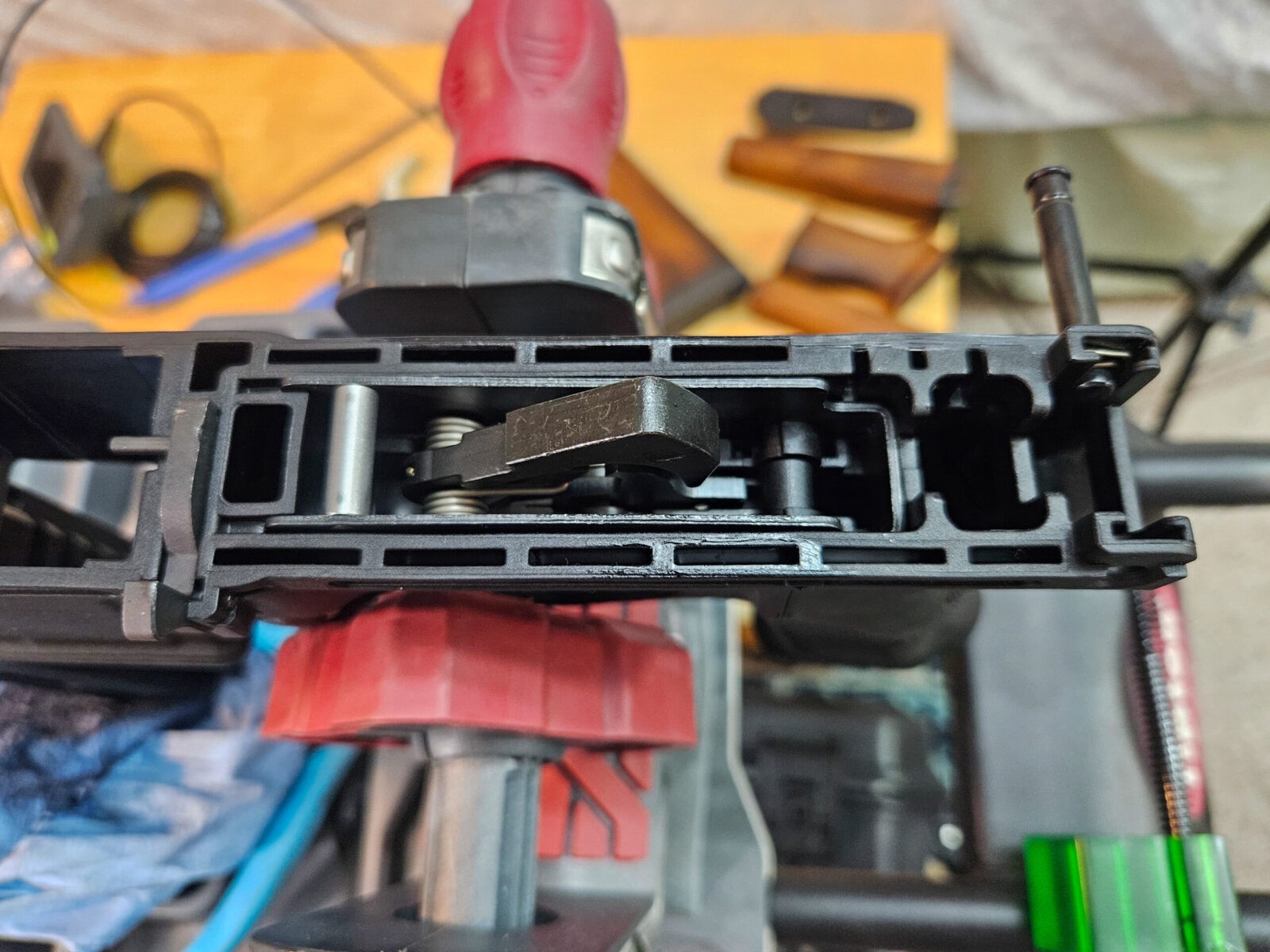
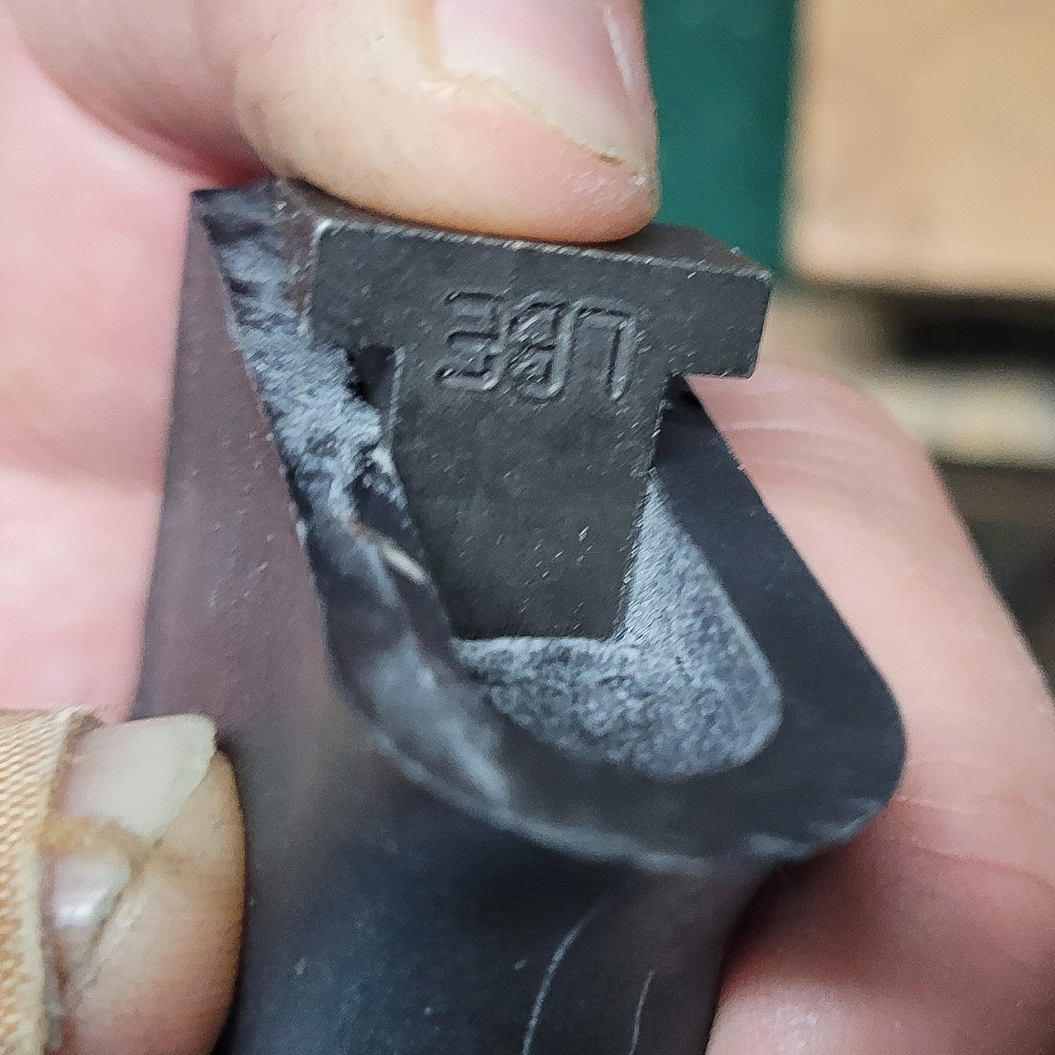
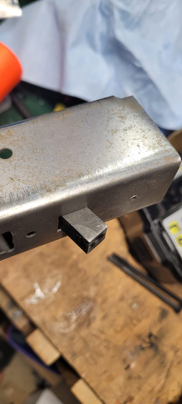
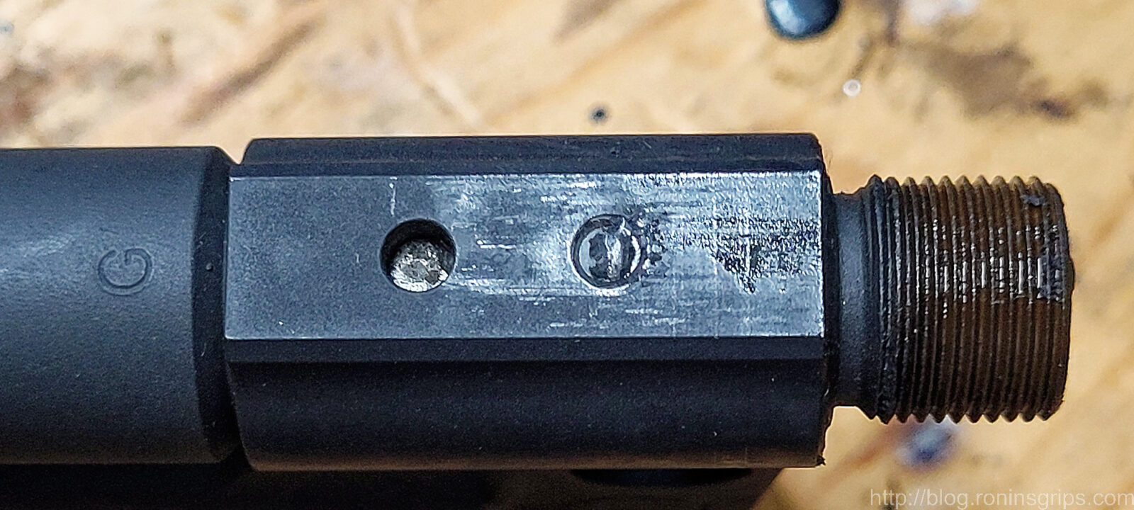
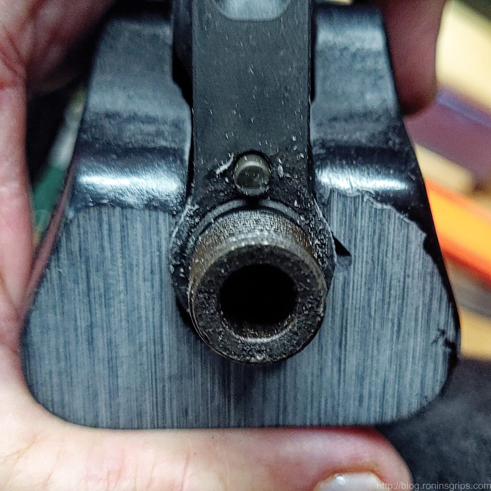
What is keeping the grip from sitting all the way is the grip nut – the small square forging that the pistol grip screw threads into for securing the grip against the receiver and trigger guard. It’s just a tad too long and the inside top of the grip is hitting it.
The grip nut is hitting the inside top of the grip. That inside top shelf was in the original grip. Maybe they had a grip reinforcement plate or shorter grip nuts when using this style of grip – I’m not sure.
Not all grip nuts are too long – this is a Romy G kit that I built way, way back sometime between 2004 and 2006. I know I did not need to trim the nut. This is what threw me off when guys said they weren’t fitting. In hindsight, different countries and makers of grip nuts having different lengths isn’t surprising – you often see a lot of differing parts tolerances across AK makers and models.
Trimming the Nut
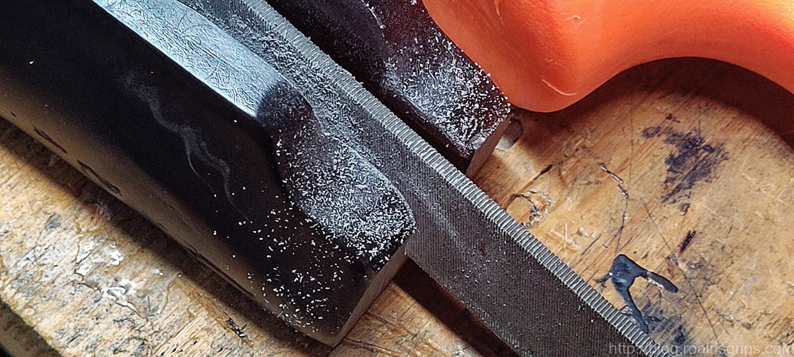
At this point, I can’t change the mold so you need to make any adjustments on your end. You either need to carve open the inside top of the grip using a bur, sanding tip or even a small 1-2″ saw blade. That seems like a lot of work – the easiest seems to be to file or grind the grip nut’s bottom so it is a tad shorter.
If you want to save your original grip nut, you can buy another and trim it if you want. Any AKM-style grip nut ought to work. For the screw though, use the one we supply with the grip.
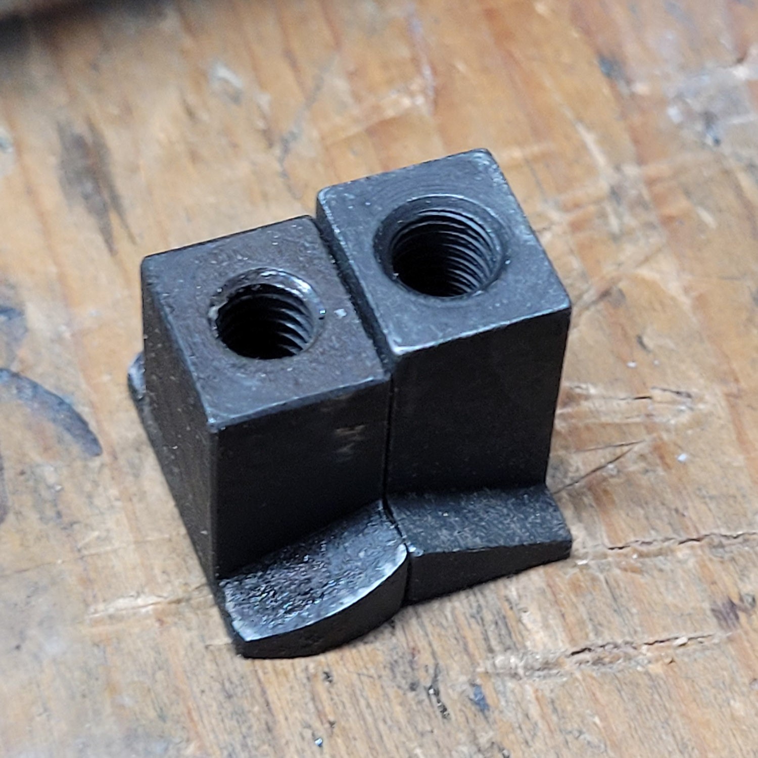
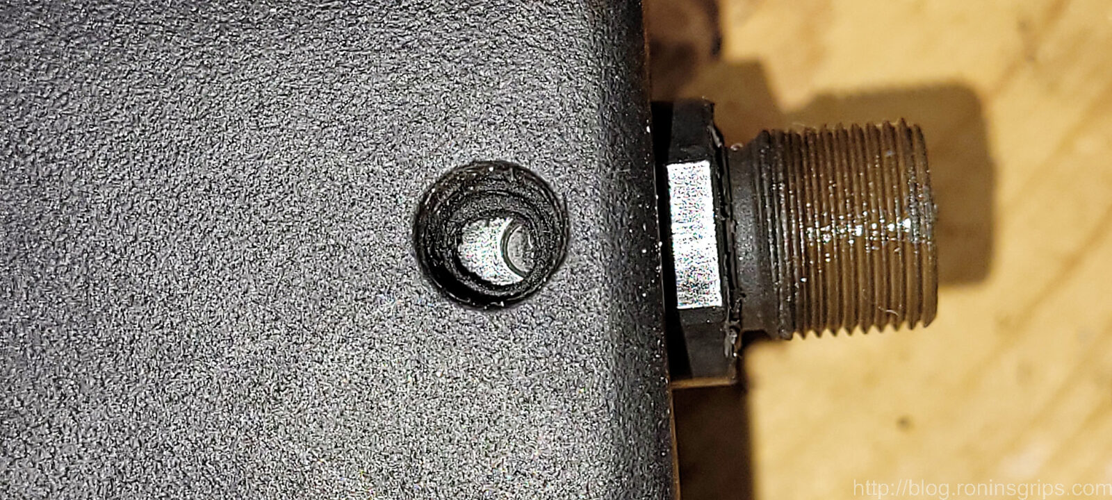
The left is a Romanian MD.63 nut and the right is a new slightly taller LBE Unlimited nut, The LBE is just a tad taller but either one would need to be trimmed to sit flush. Regardless, it is the part of the grip nut that is face up in this photo that you need to shorten via a file, sanding belt, end mill or whatever. Normally, this flat part is facing downwards the the grip screw slides into it.
It’s that bottom edge that needs to be trimmed.
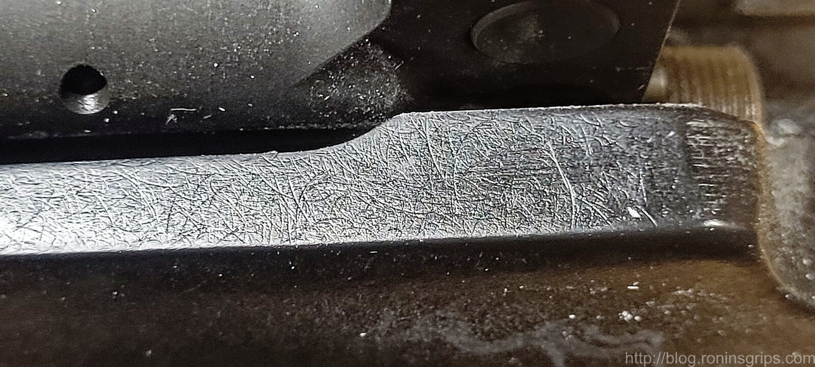
To fit it, trim off a bit and test over and over. You don’t need to do it all at once. If the threads seem off at some point, run the grip screw in from the other direction to clear the threads.
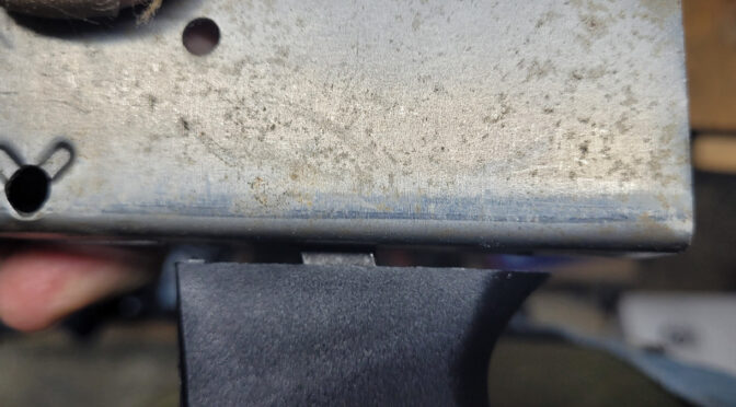
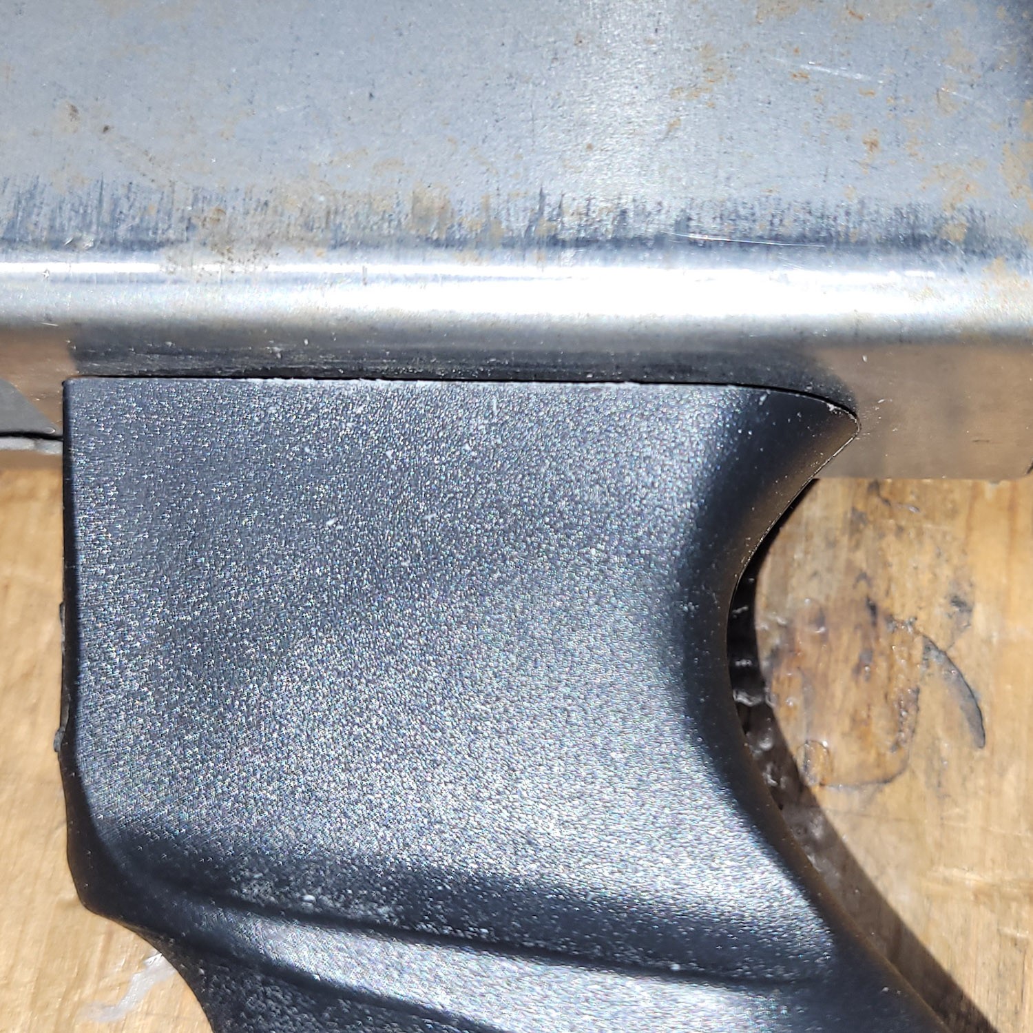
Trim the bottom of the grip nut until the grip sits nice and flush against the receiver.
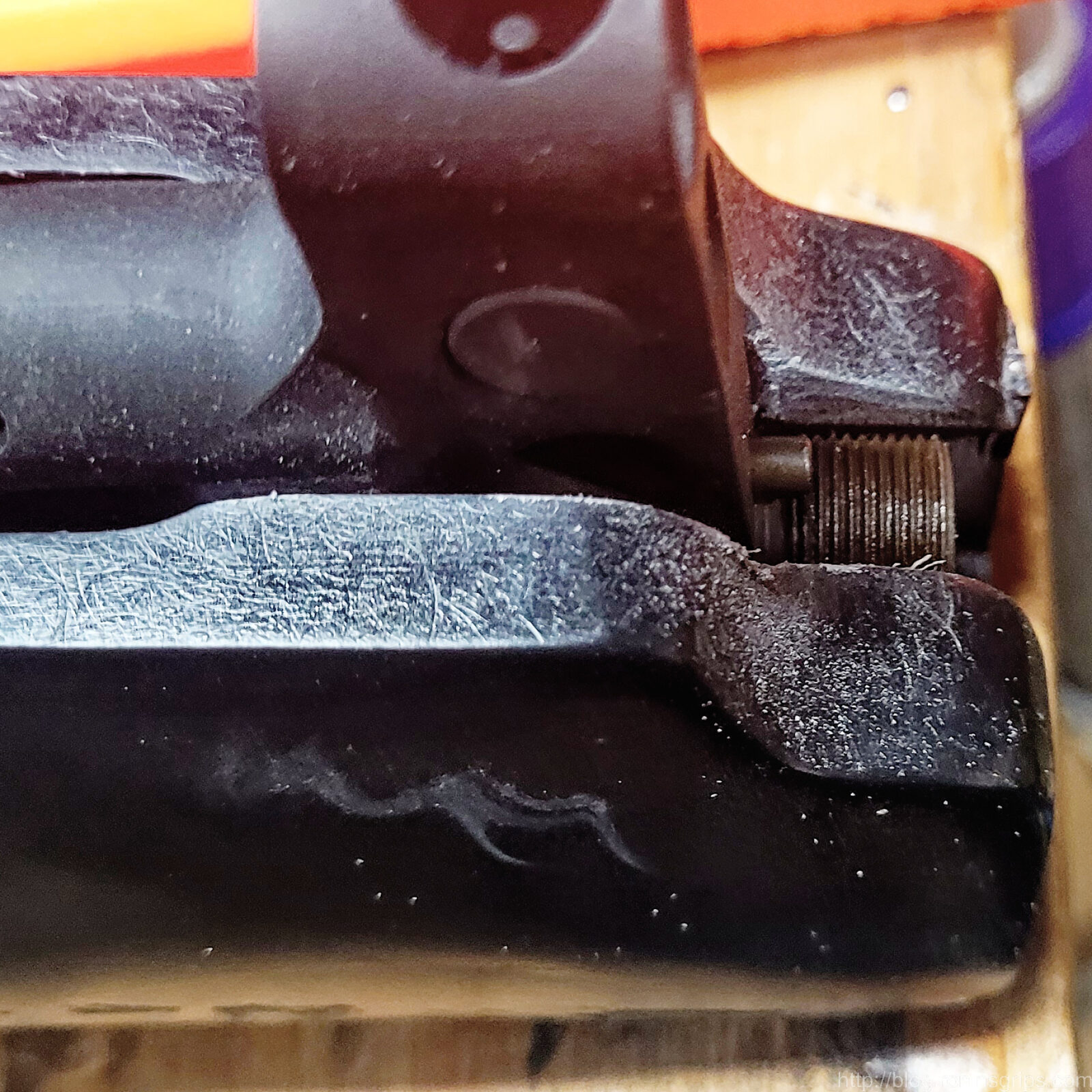
By the way, if you are wondering what the grip is against, it is an old AK-Builder bent flat where I messed up the top rails years ago and now use it for mocking things up.
Summary
I didn’t know the grip nut length was going to be a problem and don’t have a way to change the molds at this point. What I’d recommend is either trimming your nut or buying a replacement and trimming it as needed.
I hope this helps you out.
If you find this post useful, please share the link on Facebook, with your friends, etc. Your support is much appreciated and if you have any feedback, please email me at in**@*********ps.com. Please note that for links to other websites, I may be paid via an affiliate program such as Avantlink, Impact, Amazon and eBay.
By popular demand we are bringing back our C39 Micro handguard that can also be fit to the Micro Draco. The purpose of this post is to share some fitment issues you need to be aware of and general guidance.
In my honest opinion, installing the Orca requires some expertise with woodworking or machining and is not something I would recommend to a novice. it is not just a drop in handguard like you would expect with an AR handguard for example.
Safe Use Is Your Responsibility – This is a short handguard on a short pistol. Please be mindful of safety whenever you are shooting it. Do not let anyone with a weak upper body, grip or who can’t control the pistol, fire the pistol.
Why You Must Fit the Handguard – A First-Hand Lesson
There are two reasons – first, there are a lot of things that can differ pistol to pistol and the pressure casting method we use has a tolerance that will require you to make some adjustments.
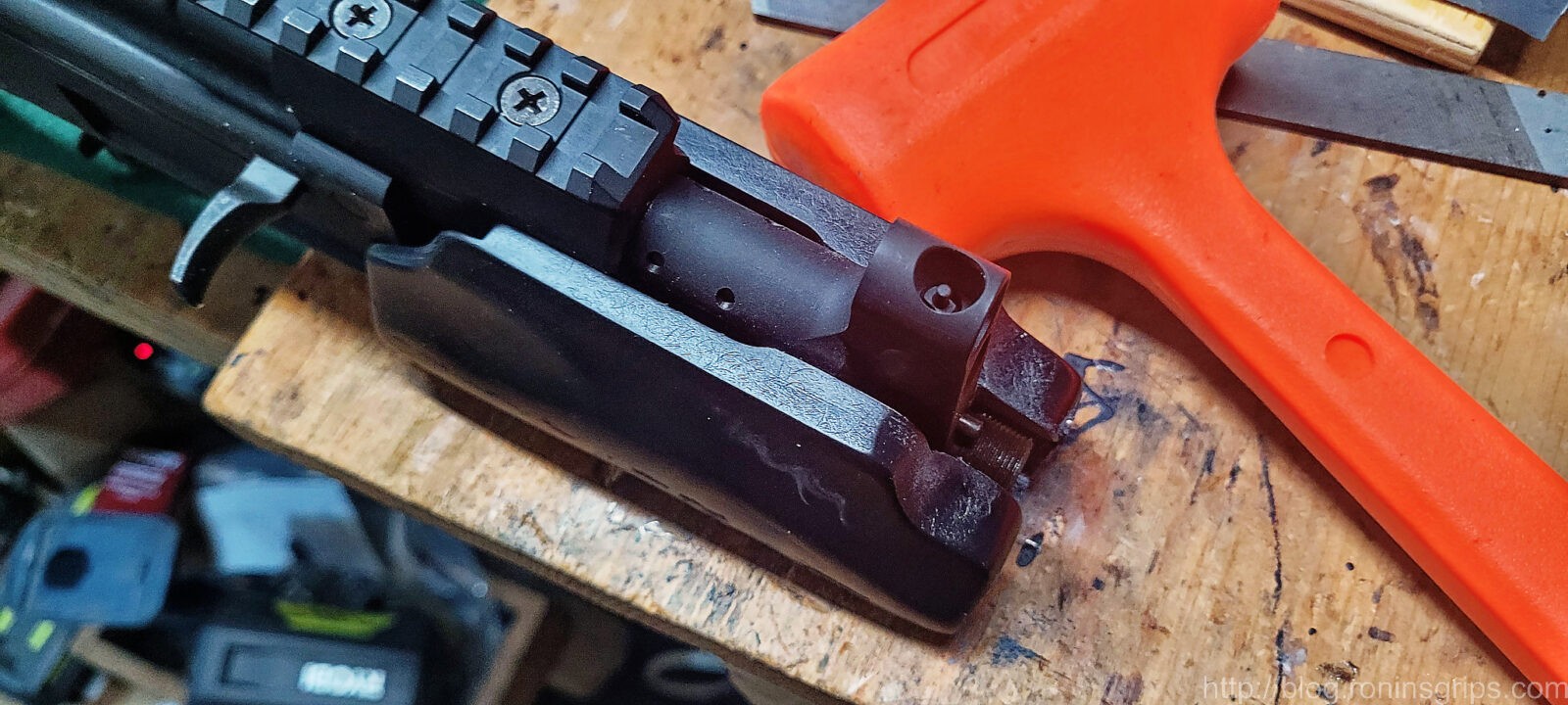
Second reason, the rear of the handguard must butt up against the front of the receiver to transfer the stress of recoil. If these surfaces do not contact each other, all of the stress will be placed on a small #8-32 screw that can’t handle the load and will shear off – I’ll show you what I mean.
Some time early this year, my friend Scott told me the screw sheared off when his wife was shooting his C39 Micro. This caused me to stop bringing the Orca handguard back until I sorted things out.
So, I finally had some time to look at it and the handguard wasn’t fully seated back against the receiver. His was the first Orca I made and I missed it. So, the Orca beat the heck out of the screw until it snapped off.
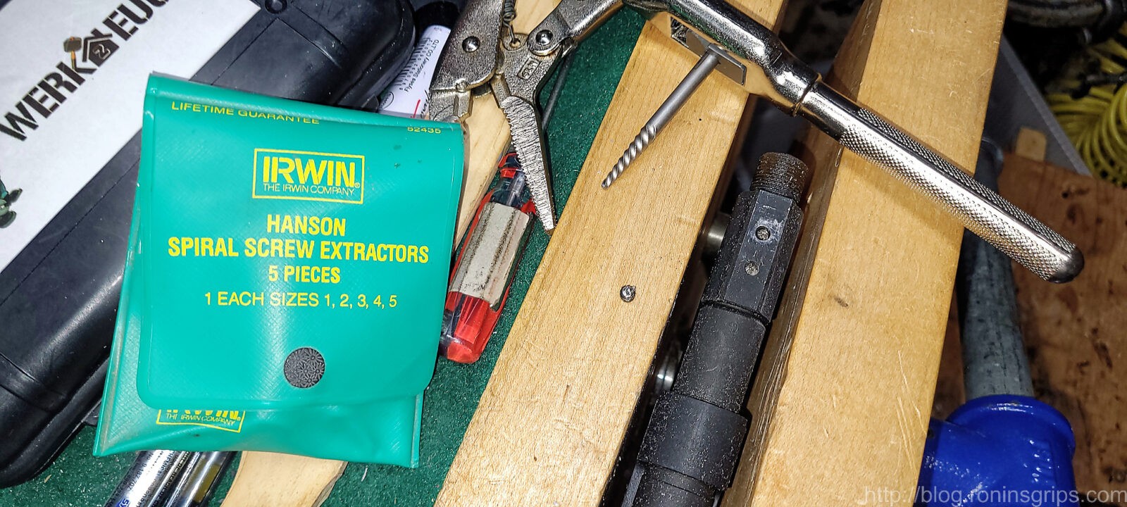
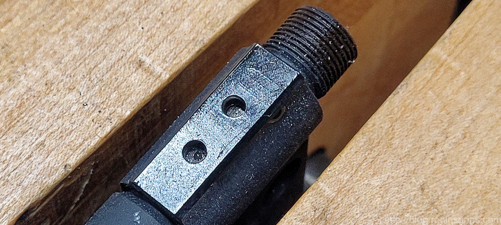
The handguard is firmly against the receiver and you can see what was left of the screw was towards the front of the hole. This tells you that I messed up installing it years ago and the #8 screw was taking all of the load.The screw sheared off right at the top of the hol.I sanded it flat, center punched the screw, drilled a hole and then used a Hanson screw extractor to back it out.Thanks to Brownell’s Oxpho-Blue, you would never know the original finish was missing.
Fitting the Handguard the Right Way to a C39 Micro
Armed with what went wrong, I dug in. I had the original handguard and I also cast two new ones to test with. For those of you reading this to install an Orca on a Micro Draco, read this for information but there will be a section further down with a video you need to watch.
Safety Brief: Before you do anything with your pistol, please make sure it is unloaded and safe.
Okay, the plastic used is a temperature resistant glass fiber reinforced urethane. It does not like to bend or compress. Think of it as a hardwood with an attitude. It can be sanded, filed, whatever you like. Wear a dustmask to avoid breathing the dust – you don’t want to do that.
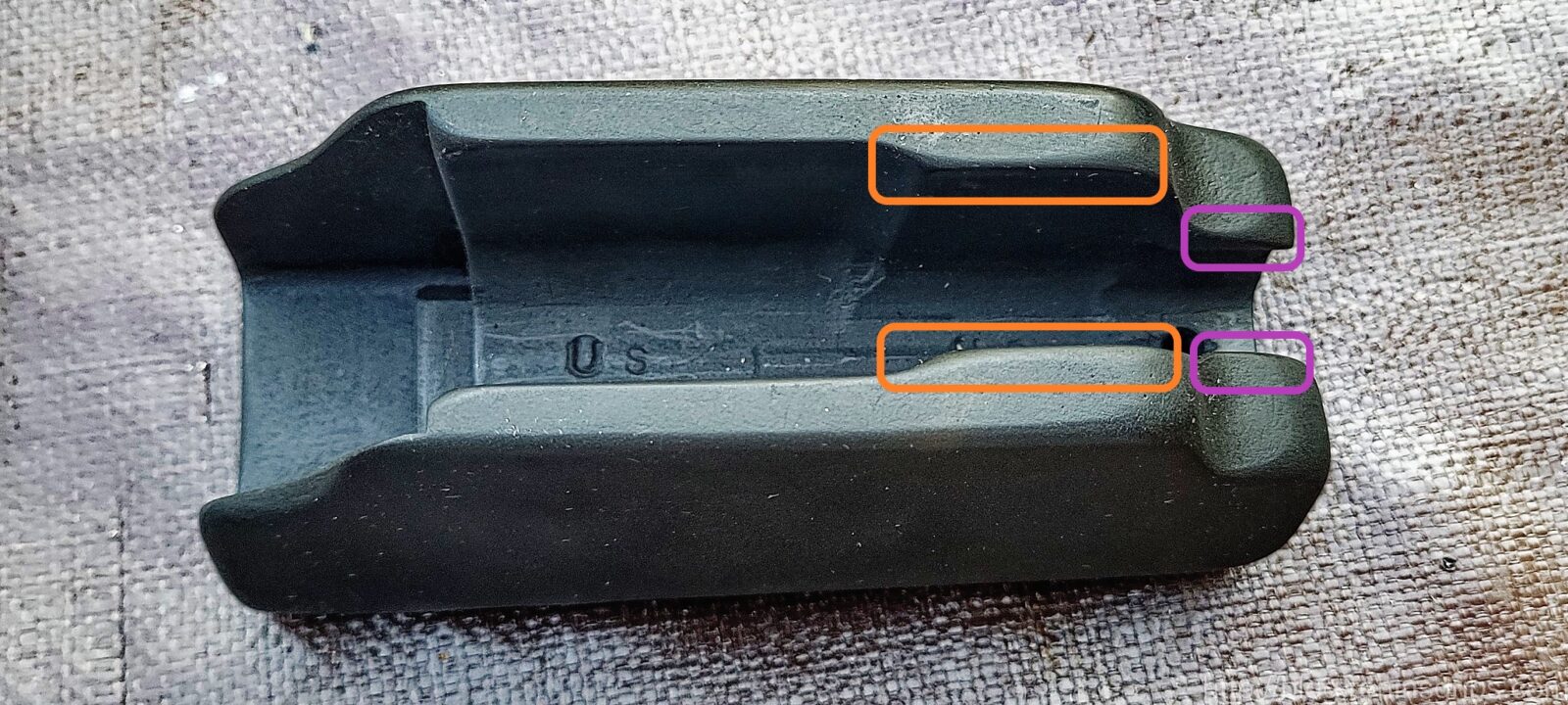
The orange areas will likely need trimming to clear your gas block and the purple areas may need adjusting to allow the area around the barrel to seat. The orange virtually always needs adjusting the but the purple may or may not.
To fit the handguard, pretty much all you need is a file or sandpaper wrapped around a couple of paint stir sticks. I just use a file and you’ll see what in the photos.
I use a file and take the same amount off each side. Count your strokes and equal pressure. Don’t try and remove everything at once – take off just a bit and test over and over.
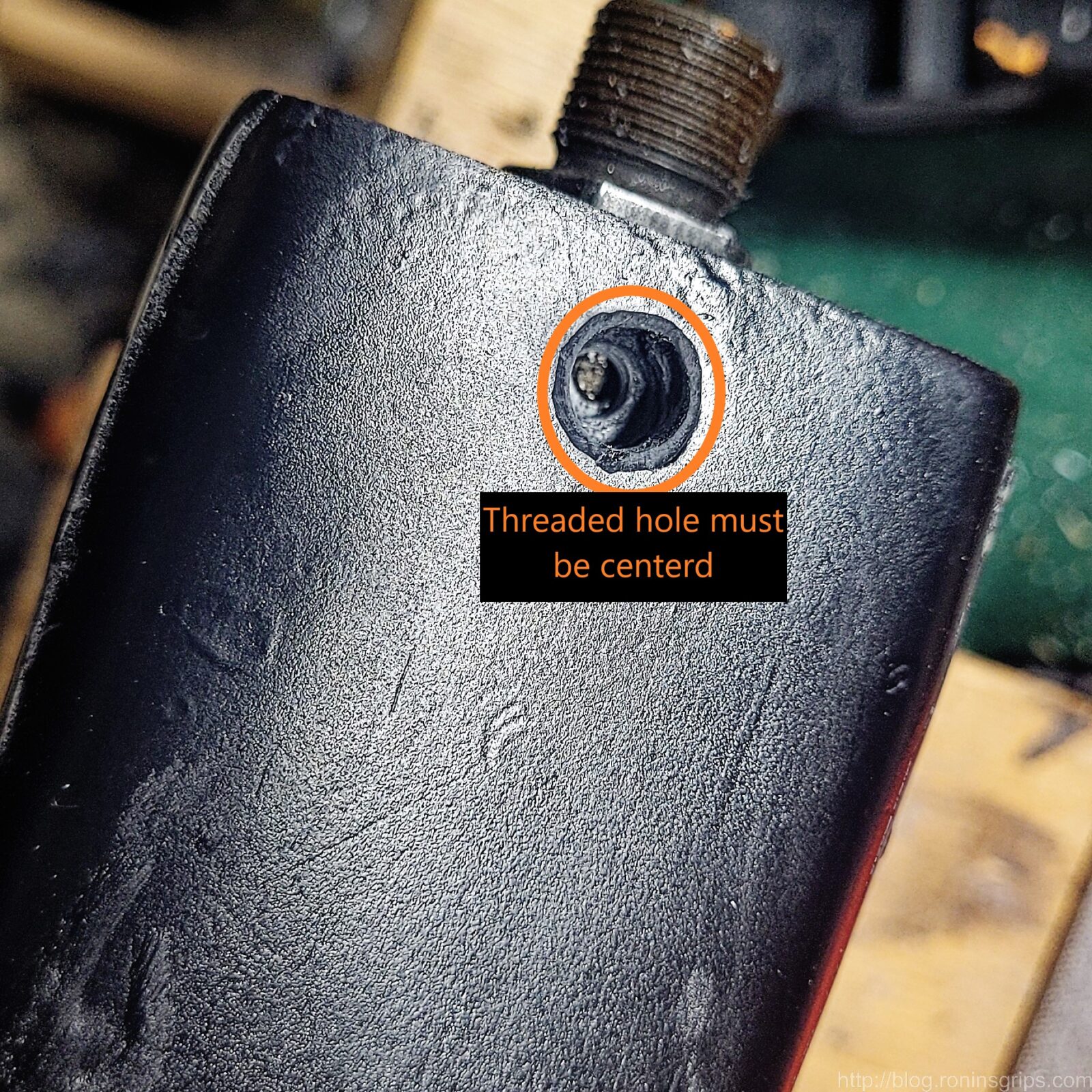
When removing material, do it equally with a few strokes from each side. If you slide the handguard on and the screw hole is off-center then you need to decide which side needs adjusting. Ideally, you don’t want to see that at all – remove material equally from both sides and do it slowly – don’t rush.
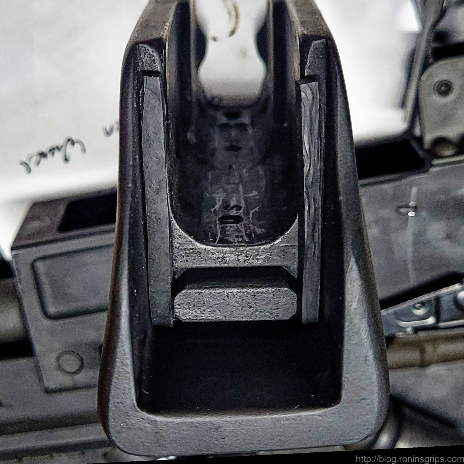
The sides need to clear the gas block and gas tube.When you are trying to clear the front, make sure the barrel is to the bottom of the handguard. Here, it is sticking because it is out of position towards the top.This test handguard had the waste plastic sawed off but no sanding that’s why the front looks so coarse. I wanted you to see that it is a snug fit up front and the barrel must sit down in the channel during fitting and testing.You will need the threaded hole to be centered.
The trick is to test fit, remove a bit of material equally and test again. I have a dead blow mallet to tap the Orca on or off but it is not done forcefully – you want snug. If you try and force it, the plastic will snap sooner or later.
The dead blow mallet is there to help me tap it on and off. It is not there for a “Mongo smash” level of force. You want a snug fit only.
Depending on your pistol and how the fitting goes you may or may not need to add a shim. A shim is a thing piece of material that closes the gap between the handguard and the front of the receiver. It can be metal strips or a high temp gasket material. Just don’t use paper or cardboard or something that heat or oil/solvents can destroy.
I had three handguards during testing. One need an 1/8th in shim and the other two needed far less – somewhere between 1/32nd and a 1/16th. I made this one so you could see it.The shims are 2″ tall and 5/32″ wide – I cut them from a sheet of high-temp abrasion resistant Buna rubber. As mentioned, these are an 1/8th” thick. You just need the sides but if you want to go all around and shim every contact surface you could. You can leave them free-floating or but a dab of super glue or your favorite adhesive behind them once you know they are what you need. Don’t glue them in until you’ve done all the testing, etc.
So that’s pretty much it for the C39 Micro – get the handguard to slide on centered over the threaded hole in the gas block and shim if needed to it seats fully.
Fitting the Micro Draco
A fellow did a real nice job documenting how he converted the Orca to fit a Micro Draco. He created this video and put it on YouTube so everyone can benefit from it:
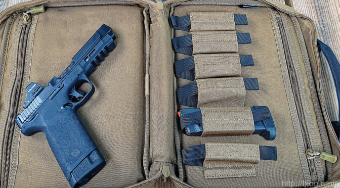
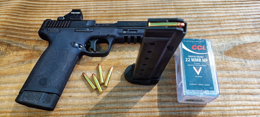
As I mentioned in the last post, I am a new owner of a S&W M&P .22 WMR pistol. It wasn’t really planned – I had young nieces coming to visit and nothing really that I would consider a good pistol for them to start with. It worked great – I have no hesitation recommending it based on my experience.
Click on one of the photos and you can navigate around and see others:
I hope you find the photos helpful. I am very impressed by the pistol – that’s for sure.
Note, I have to buy all of my parts – nothing here was paid for by sponsors, etc. I do make a small amount if you click on an ad and buy something but that is it. You’re getting my real opinion on stuff.
If you find this post useful, please share the link on Facebook, with your friends, etc. Your support is much appreciated and if you have any feedback, please email me at in**@*********ps.com. Please note that for links to other websites, I may be paid via an affiliate program such as Avantlink, Impact, Amazon and eBay.