Category Archives: Firearms Building and Gunsmithing

How to build and/or gunsmith on certain platforms.

Add A “Thumper” To A Blast Cabinet And More Than Double Your Productivity!

Okay, Ronin’s Grips started making Yugo M70 grips sometime around 2004 and rapidly added models – the challenge was that I hand polished each and every one of them. It took a ton of time, handwork and was putting my carpal tunnel through the roof. Jeff Miller of HillBilly Firearms told me to abrasive blast the grips for a better grip and a heck of a lot less handwork. I was sold – I had to change something. Jeff also gave me a few tips – get a foot control to protect the seals vs. being in the cabinet with all of the grit, put transparency film on the window of the unit to make it last longer and he told me to get a “thumper” to make the grit settle.

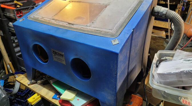
Well, way back in the day margins were super thin so I bought a large bench top abrasive blast cabinet from Cyclone Manufacturing in Dowagiac, MI – they are about an hour from my shop and I could pick it up along with the foot control, I got a box of transparency film either from Amazon or a local office supply store, but I had no idea what a “thumper” was or how important it is to productivity.

Fast forward to about a month ago. Abrasive blasting used to take me a while – blast, hit the cabinet or manually move the material around in the hopper, blast some more, whack the cabinet or move the material around … it gets old. It took me years to realize that this really sucks but blasting was so much better than polishing that I didn’t think much about it.

So, a “thumper” is basically and industrial vibrator (insert joke here) that uses an electric motor in a housing with off center weights on the shaft that then vibrate like crazy when the motor runs. I guess you could call it the power of Amazon but one day I was scrolling through Amazon and a suggested item came up – a concrete vibrator – and it looked like a small motor in a housing. I had 25 Galil grips I was going to blast and all of a sudden I remembered Jeff’s advice.

Okay, the power of a vibrator with a blast cabinet is that the vibrations cause the grit to shake down to the lowest point constantly. You can blast and blast and blast. The unit was $118 with free delivery and I figured I would give it a try.

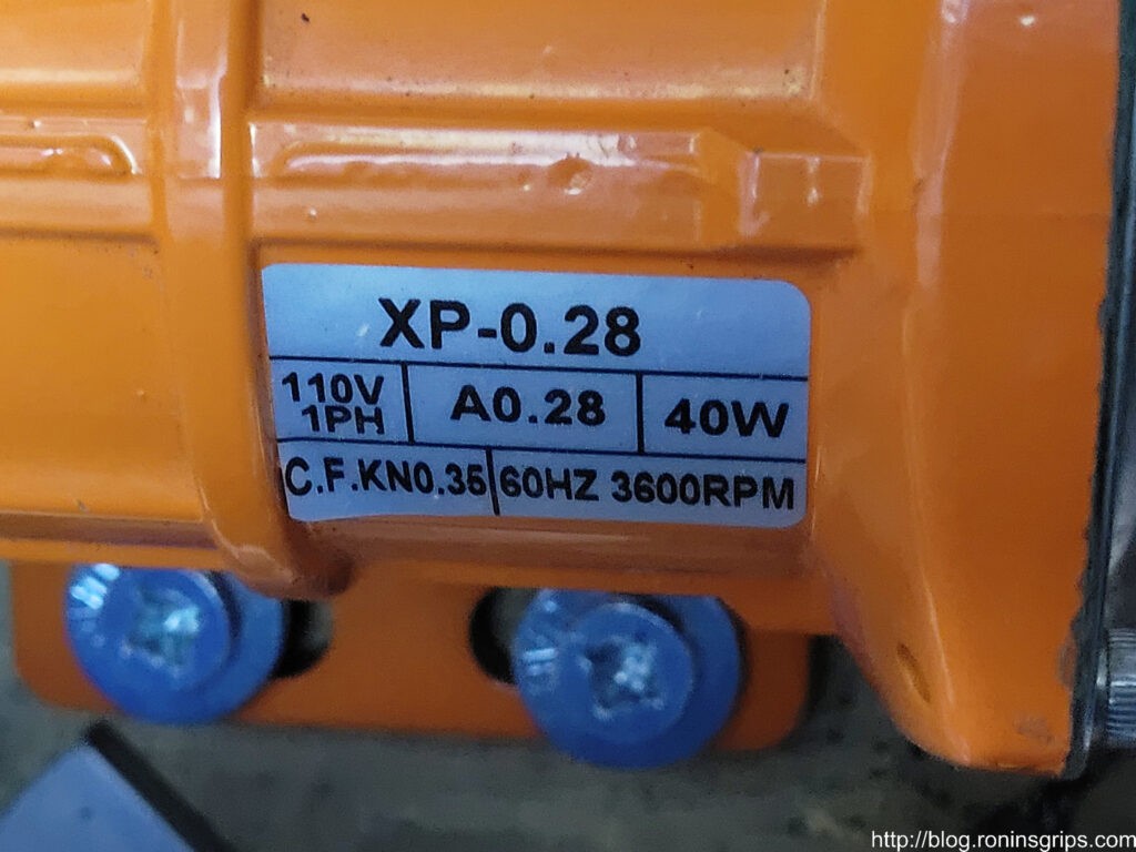
It shipped from the importer, not Amazon, and showed up a few days later – it was pretty quick as I recall. The unit was very well made other than my needing to tape up a plastic junction box on the power cord that was a little cracked and I needed to attach a 120 volt plug – it was one phase and they said about 40 watts so nothing special. The machine label says – 110V, 1 phase, 40 watts, 3600 RPM – the little thing totally kicks butt and was only $49.

Here’s a close up of the label – note it says 40 watts. There are bigger units but I don’t think you need them for an abrasive blaster.

I didn’t put it on the blaster right away because I wasn’t really sure how violent it would be and I am glad I didn’t – it vibrates like you would not believe – there is nothing subtle about it – and I immediately realized two things – 1) I was going to mount it on the free standing tool bench and not the plastic blast cabinet walls or it would eventually shake loose and 2) I needed a variable speed control to tone it down some.

Try #1

Okay, so sometimes you just have to poke fun at yourself – or at least I do. I marked the bolt holes on the 3/4″ plywood bench top and mounted the vibrator. I then plugged the power cord from the vibrator into the speed controller, the controller into a surge strip and turned it on at full speed.

I wish I had a before photo or a video of what happened next but I don’t. Every single thing on that table started vibrating right off of it. Yeah, all the grit went to the bottom on the blast table but the blast table was headed to the edge of the bench too. Whoa! I hit the off switch.

Try #2

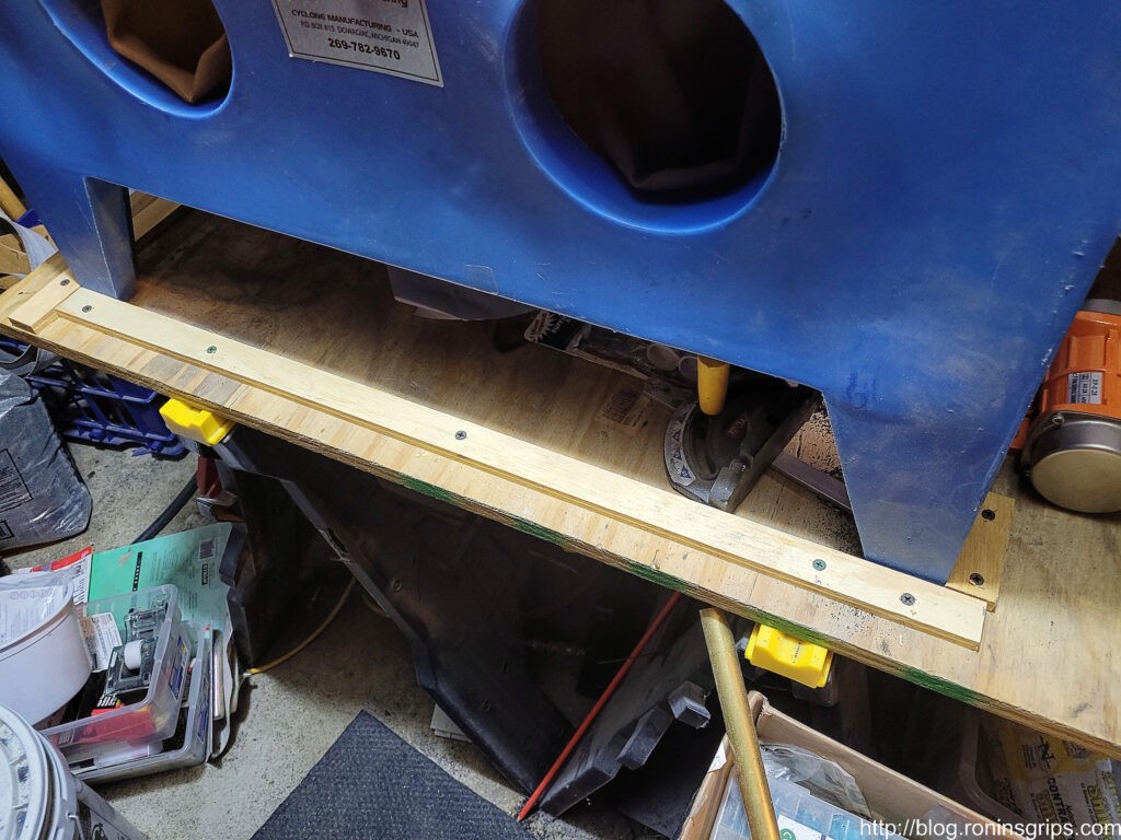
I simply took some strips of plywood and added a cradle around the legs to limit travel. That worked. Time to try blasting some stuff.

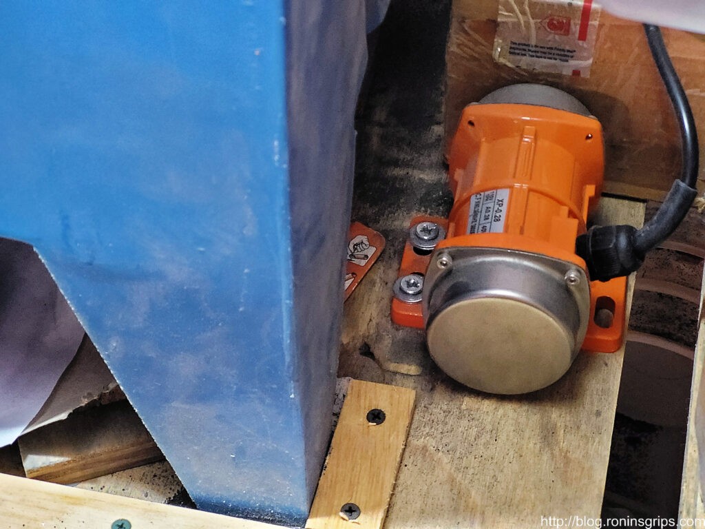
Here’s the vibrator.
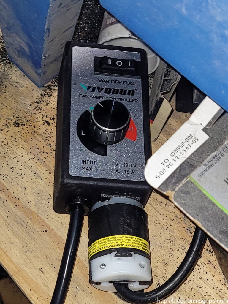
Here’s the speed controller.
Another view of the strips to limit travel. Everything on the floor had been on the workbench before I turned the vibrator on the first time 🙂 By the way, the 3/4″ plywood top is screws into the stands it is on.

Actually Blasting

Folks, it is night and day different – stunningly different. Because I don’t have to stop and whack the side of the baster or reach in and move grit around, I’d bet I’m getting work done 2-3 times faster. A bench top blaster doesn’t have a very deep bottom so without a thumper, I spent a lot of time moving grit over to the pick ,up.

Another fun lesson learned. Over the years, I’ve developed the habit of putting my chin on the plexiglass as I focused on doing the work. Don’t do that. I put my chin down on the vibrating plexiglass and it felt like someone was playing the tambourine with my teeth 🙂

Those are two IMI Galil grips getting blasted. What an amazing difference.

In Conclusion

This is one time I can honestly tell you that I have one regret – I should have done this years and years ago. Wow. It was worth it! I’ve used vibrator and speed controller both extensively for a little over a month and it’s a great combo. I don’t use the slowest speed but I am closer to the low end on the dial than I am the fastest speed.

Note, I got lucky with my first purchase. I really wasn’t sure what size to buy but the 40 watt unit has worked great. I can’t imagine anyone needing a bigger unit for a blast cabinet. These generic industrial vibrators have all kinds of uses including for the movement of powders, grains, rock, etc. so they sell bigger and more powerful ones as well.

I’d highly recommend this to anyone who has a ton of blasting to do and is getting tired of having to stop and manually move grit around.


Note, I have to buy all of my parts – nothing here was paid for by sponsors, etc. I do make a small amount if you click on an ad and buy something but that is it. You’re getting my real opinion on stuff.

If you find this post useful, please share the link on Facebook, with your friends, etc. Your support is much appreciated and if you have any feedback, please email me at in**@ro*********.com. Please note that for links to other websites, I may be paid via an affiliate program such as Avantlink, Impact, Amazon and eBay.


My Adventures With Rock Island Armory 9mm Extractors

Starting in 2021, I started to offer 10mm magazines for the Rock Island Armory A2 HC pistols – “A2” being a marketing opportunity to refer to the next generation 1911A1 pistol prototyping the US Army did starting in 2004 that experimented with different sights, extractors, mainsprings, etc. The “HC” stands for high capacity and reflects the RIA pistols are using a staggered magazine design to hold far more rounds than a single stack could.

At any rate, I had a number of customers ask me to produce mags for the 9mm RIA A2 HC pistols – the 51679 Tac Ultra and the 56645 Pro Ultra Match HC. Our 10mm mags had proven to be very successful and after enough requests, I decided to enter the 9mm magazine market.

One thing I learned with making AK grips is that you really need to have the weapon to make a part for it. This allows you to check fitment, reinforce potentially weak areas, etc. So, when I started with the 10mm mags, I bought a 52009 Rock Ultra HC and later a 56862 Tac Ultra Match HC. Why? Because you also find that a given firearm may differ enough that if you build and test only with it, you may not be making something others can use.

There’s an engineering problem called “stacked tolerance”. Every part has a specification that says, for example “9.0mm” and then there is a tolerance specified – for example “+/- .01”. That means the part produced can range from 8.99 to 9.01 in size. Make an assembly and all of those tolerances may combine, or “stack” in such a way that if you build a part to work for that particular unit then another assembly that happens to stack in the other direction may not be able to use that part. Testing on multiple pistols helps with a testing – at least a bit because you are reducing the odds of one pistol having a problem or working and others not.

So, by having both the 52009 and 56862 10mm pistols, I could test magazines to make sure they fed right, dropped free, etc. With the 9mm pistols, I had limited funds and just started with the 51679 – the Tac Ultra. That decision bit me hard.

The Initial Magazine Prototyping Didn’t Make Sense

When I prototype, I buy a bunch of original magazines and then start looking for what is close enough to modify and start tinkering with the feed lips, feed angles, the spring and the follower. To keep track of things, I applied numbered stickers to every magazine and kept track of the dimensions plus performance.

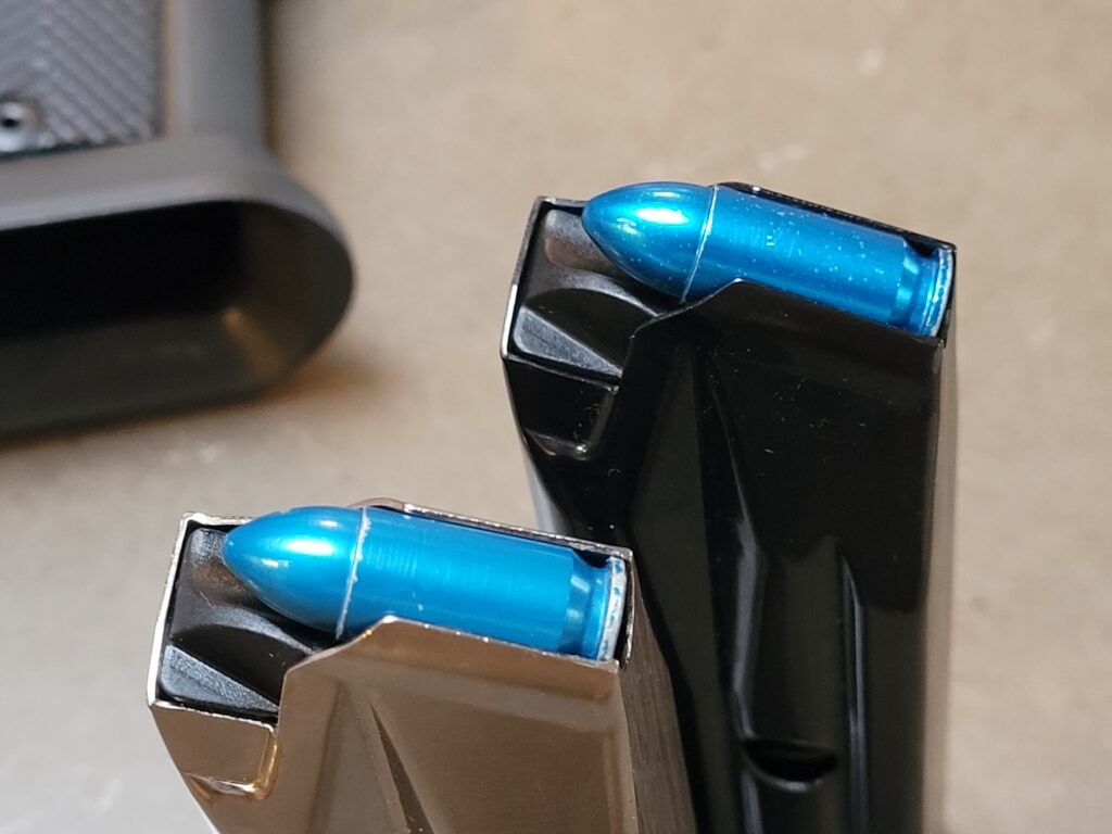
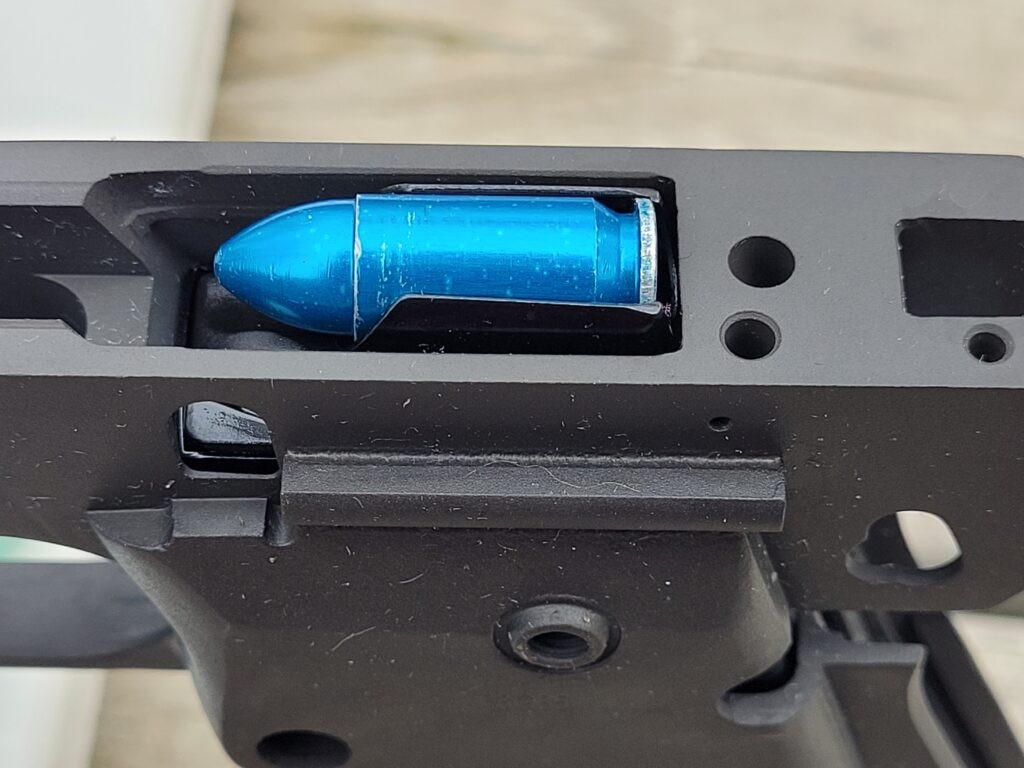
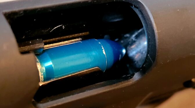
What I also learned with the 10mm mags is that the best dummy rounds are the machined aluminum A-Zoom Snap-Caps. Dummy rounds that are made from a case and a bullet will see the bullet pushed back into the case and/or get deformed after some fairly low number of cycles. The machined aluminum A-Zoom Snap-Caps are dimensionally accurate and can cycle hundreds of times before needing to be replaced. By the way, don’t do this type of work with live rounds – it’s an accident waiting to happen.

Back to the 9mm world, I was working on the mags and things just didn’t make sense. A magazine would work and then it wouldn’t. One set of dimensions would work and then they wouldn’t. Something just wasn’t adding up. The pistol would fail to eject randomly, I’d then have the old round and the new round in the slide at the same time and of course it jammed.

It had to be the mags right? I blew through a bunch of mags and time before it dawned on me that the pistol itself must have issues. I hadn’t questioned it before because the pistol was brand new out of the box. Sure, I had cleaned and lubed it first before cycling hundreds of snap caps through it. The problem was that I assumed it was good to go and the initial testing seemed to show a reliable pistol … but I only tested a few mags worth of snap caps – maybe 34-52 cycles max.

Testing The First Pistol

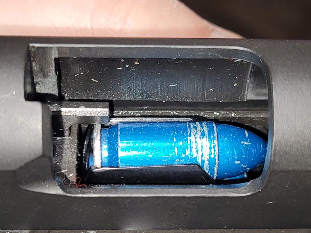
I loaded a magazine up, racked the slide and loaded a snap cap. I then pulled the slide back slowly and the extractor lost control of the extracted round as I pulled the slide to the rear. That wasn’t supposed to happen. If I went slow, it would either fail to extract completely or lose control of the round.

I’m not a 1911 gunsmithing guru but I had to learn some stuff really fast. I knew if I sent the pistol back to Rock Island/Armscor, it would be at least a month before I would get it back. So I read posts and watched videos that explained the pistol had an extractor problem and how to correct it. I bought a few different brands of 9mm extractors, the Brownells extractor tool, the Jack Weigand extractor gauge and tensioning tool.

Boy, I could not get that thing to work even after trying a few different brand extractors and a Wilson. At this point I was pretty ticked off. My last best guess was that the extractor looked like it was clocked slightly. When I inserted the Weigand 9mm gauge, I could feel initial tension as I inserted it and then it would drop off rapidly as I inserted the gauge the rest of the way (it centers over the firing pin hole). Rather than do a new firing pin stop plate, I decided to stop chasing best guesses mainly because I was blowing time I did not have to spend. The pistol was under warranty so feeling both stupid and defeated, I finally got an RMA to send the pistol back.

No, I’m Not Incredibly Patient

In the meantime, I bought a 56645 Pro Ultra Match HC and it has worked great – no problems at all. I was able to work out the details on the mags. Now, I am not patient so I actually ordered a second 51679 Tac Ultra that I looked at, cycled a few rounds through but really didn’t use a great deal – my primary go-to test platform was the 56862 … until I decided to take some photos about the RIA 9mm A2 HC pistols and looked at the 51679’s extractor.

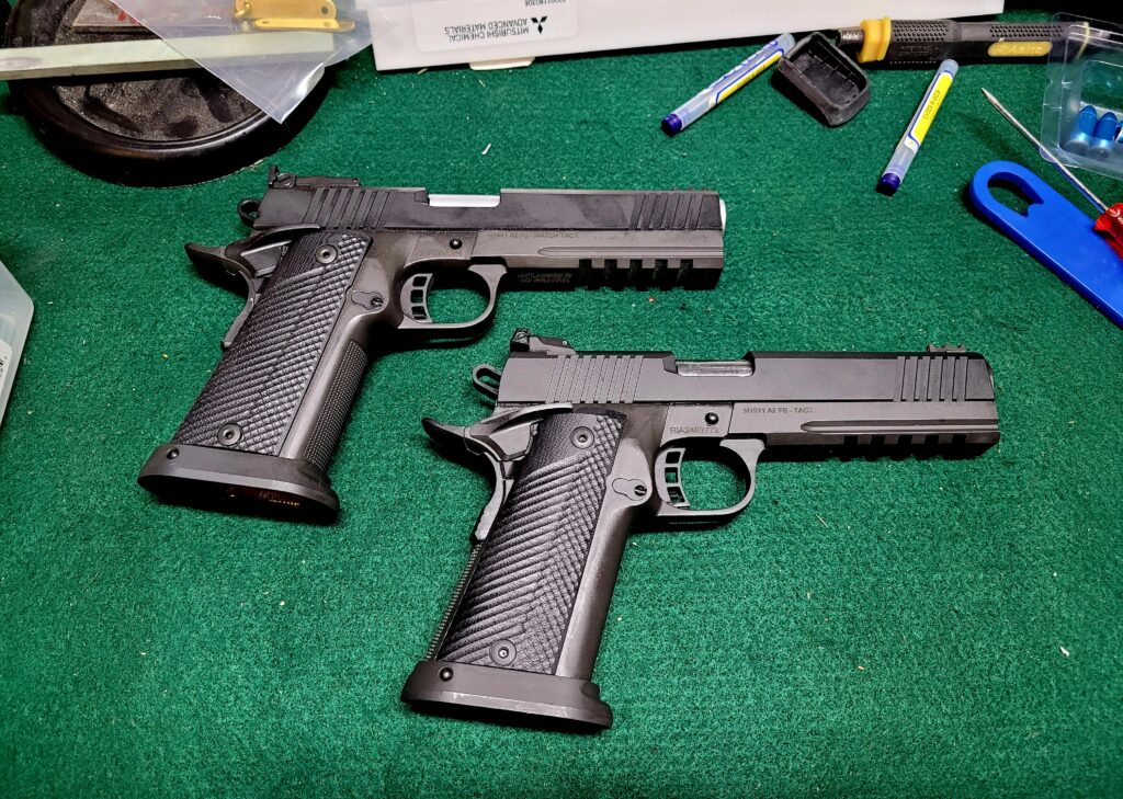
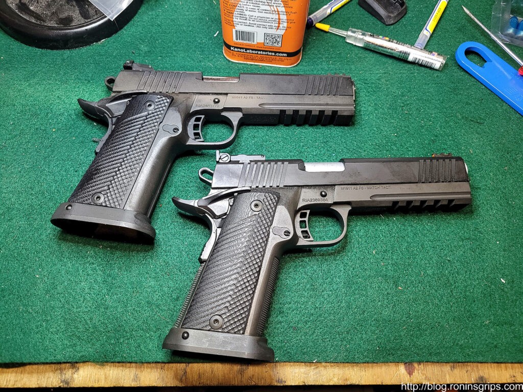
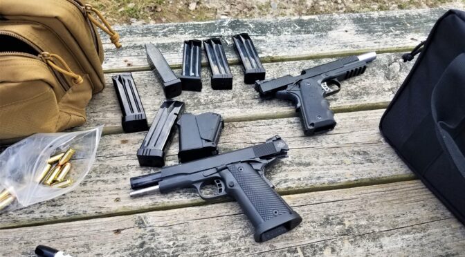
The second 51679 is at the top and the 56862 Tac Ultra Match is at the bottom. The Match pistol has nice checkering on the front of the grip, the top of the exposed barrel is a grey matte finish and has a target rear sight.

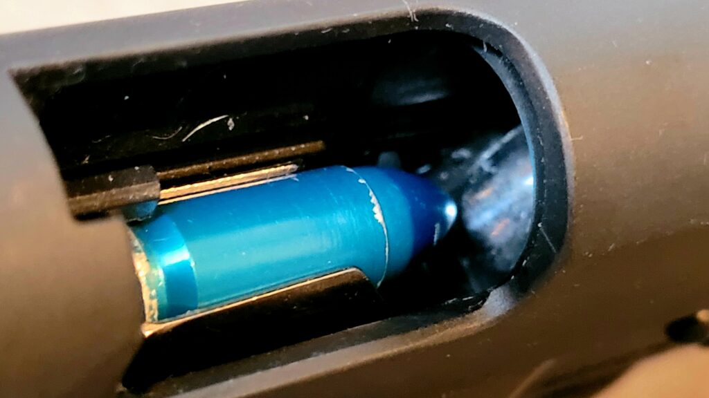
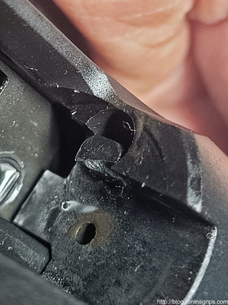
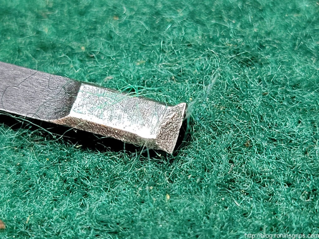
“You’ve got to be kidding me” – I thought to myself. Inserting a choice F bomb of course. The extractor in the brand new 51679 that probably has less than 100 hand cycled Zoom snap caps through it was almost completely broken off other than a little tiny nub on one end. WTF?!?!

I was happily taking photos for a blog post when I saw the silver grain of the busted extractor. Yeah, I was swearing up a storm. Really?

Okay, two 51679s bought from different vendors off Gunbroker about a month apart both having extraction problems …. wow. I’ll be honest – I’m disappointed. RIA 1911s are econobox models but they usually work – so, no, I’m not remotely happy not to mention jumping through hoops waiting for ever for their customer service to respond. I did learn a bunch though and will share with you what I did and what you can do if you want to.

Metal Injection Molding For Extractors Isn’t The Best Choice

The problem is that to keep costs down, Armscor, who owns the Rock Island brand, make the ejector using Metal Injection Molding (MIM). If you search on the web, you will see a ton of guys arguing against the use of MIM in high stress parts. As I just learned with extractors, it’s not the strongest manufacturing approach – making them from forged high-quality steel is a far better idea.

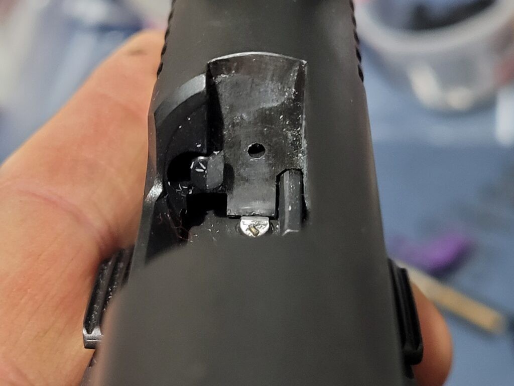
I removed the extractor from the pistol and zoomed in as best I could to get you this photo. You can see the grainy structure that is a signature of metal injection molding. That nub at the top right edge in the photo was just enough to yank the case out of the chamber … sometimes.

Okay, if you get a new RIA 9mm pistol, check the extractor out of the box. Clean and lube it, go to the range and keep your eye on the extractor. If it breaks you have two options – send it back to Rock Island/Armscor for a RMA repair or do it yourself. Heck, you could even just replace the extractor yourself before you have a problem if you want to.

I Decided To Replace the Extractor Myself

I learned a ton on that first pistol plus I had all of the tools and spare Wilson Combat extractors. I just needed to trust in my abilities a bit more and try it again. If there’s one thing I know about myself, it’s that I am persistent and don’t give up easy. With this in mind, I dove back in again with far better results.

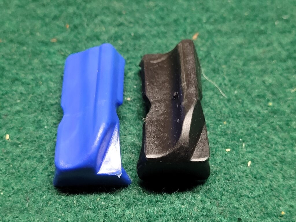
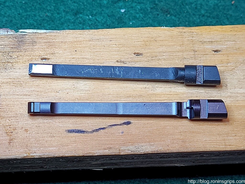
The top is the failed Rock Island 9mm ejector and it is a series 70 design. The lower extractor is a state of the art forged 9mm extractor from Wilson Combat. It is a series 80 design but will work just fine in a series 70 pistol.

First, let me explain why I went with a Wilson “Bullet Proof” .38/9mm extractor. They have an excellent reputation a number of guys posted about throwing away their RIA ejector and installing a Wilson. Instead of being MIM, here’s what Wilson says about their extractors:

  • Fully Machined from S7 shockproof tool steel with a tensile strength of 275,000 PSI
  • Optimized hook design for maximum strength and case rim contact
  • Hook location tolerances held to +/- .001″
  • Radiused corners for extended life and smooth feeding
  • Enhanced design holds tension longer over factory part many times over
  • Heat treated to optimum hardness and cryogenically treated
  • Guaranteed for life against breakage or we will replace at no cost to you

Note: I went with a series 80 extractor because they were in stock even though the RIA pistols are based on a series 70 design. You can use a series 80 extractor in a series 70 pistol but not vice versa. You can get them from Brownells, Wilson directly and other places.

You don’t need specialized tools but if you can afford them, I would highly recommend the following:

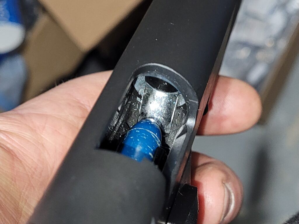
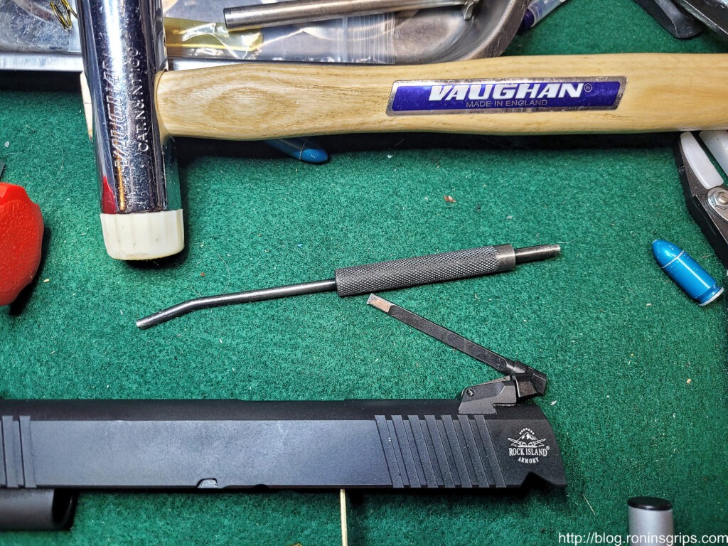
The long angled tool is the 1911 Extractor Tool from Brownells and totally worth it in my opinion. The long angled end lets you reach into the slide and push extractor back and then down into the hole for removal. The other end is perfect sized for pushing down the firing pin to aid with the removal and installation of the firing pin stop. Note the blue A-Zoom snap cap – that is the color of their volume packs of rounds. Exact same material and tolerances – just a different color.
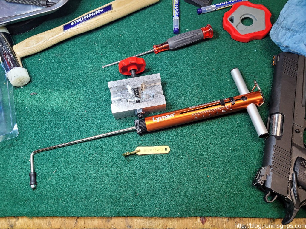
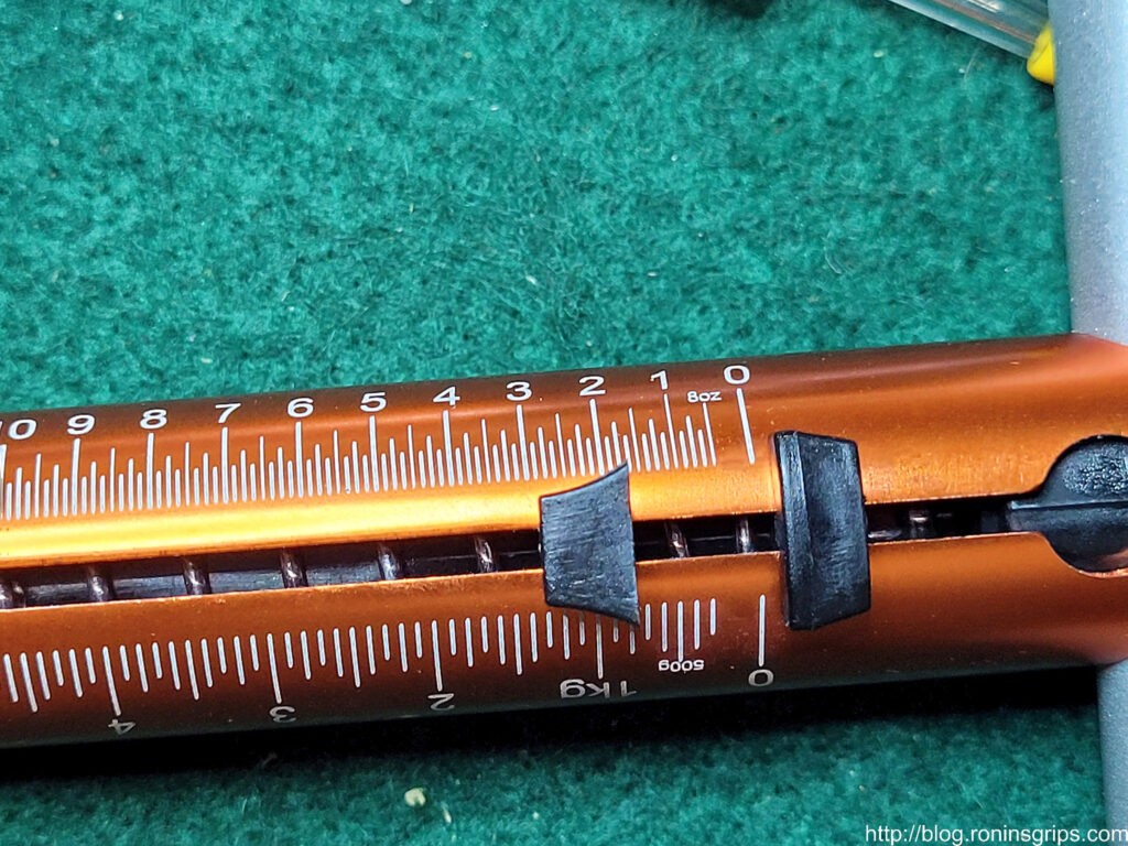
The silver block with the red handle is Weigand’s tool for adjusting extractor tension. The big orange thing is the Lyman mechanical trigger pull gauge. The brass plate is the gauge with a brass S-hook that I added. The gauge is sold as a set and each end is for a different caliber. The hole you see is actually for lining up on the firing pin hole – I just added the S-hook on the .38 end because I don’t have any plans to shoot .38 Super. Note, the small blade screw driver makes it real easy to nudge the firing pin up or down so the firing pin stop plate can be pushed into position.
Polish the Extractor

From what I read and saw, the Wilson extractor is practically ready out of the box other than setting the tension. Some guys recommended polishing the surfaces where the cartridge will come in contact and I did that with one of the small rubberized abrasive polishing bits in my Dremel.

How to Install

Make sure your pistol is unloaded – that the chamber is empty and a loaded magazine is not inserted. In short, work safe. Also, do not use live ammo for testing – use snap caps.
Let me give you an overview and then a couple of videos to watch:

  1. Remove the slide
  2. Remove the firing pin stop plate by pushing down with the straight short end of the extractor tool and then slide the plate off. Be CAREFUL that the firing pin and/or spring don’t come flying out as you remove the plate.
  3. Push the extractor backwards by pushing the head of extractor backwards down the hole out the rear of the slide
  4. Insert the new extractor and line it up so the stop plate can be re-inserted. It needs to line up with the top and bottom of the stop plate groove and it needs to be straight up and down parallel to the sides. You don’t need to install the firing pin and spring until you are done.
  5. Insert the Weigand gauge and pull it out using the trigger pull gauge to find out how many ounces it takes.
  6. Use the Weigand tensioning tool to increase or decrease the tension. I dialed mine in to 28 ounces (1.75 pounds).
  7. You can try testing feeding and extracting dummy rounds to see how it performs. The extractor should maintain control until the extracted dummy round hits the ejector.
  8. Once it is dialed in, you can then re-install the firing pin return spring, lube the firing pin and reinstall it also.
  9. There’s a trick to the plate – wiggle it in and push down the firing pin enough to get the plate to sit on the “shelf” at the rear. You can then maintain pressure on the plate and use the other hand to use the extractor tool to push the firing pin down far enough and hold it there while you push the plate back into place.

More Details

Wilson has a video on how to change to their extractor and a bit about setting the tension:

Now, I also read the Brownell’s blog post about extractors plus a more detailed Wilson Combat instructional PDF file.

The following is a video of Jack Weigand explaining how to use his extractor gauges and tensioning tool:

Adjusting The Extractor Landing Pad

The most detailed post and guidance in general about extractors that I read is here – and if you read down, you will get to sections/replies about 9mm extractors. One thing you will notice discussed is reprofiling the “fitting pad” to better fit the radius of the extractor hole. I stoned and polished the fitting pad to be more rounded but that was it. I put more emphasis on getting a weight in the 25-28oz range and did do that after may 3-4 tries.

Pulling the gauge out the final time was about 1-3/4 pounds which is 28 oz. In testing the pistol, extraction was just fine.

Was The Match Pistol Higher End?

I wondered if maybe more care was put into the match pistol. There are some nice perks in terms of features but the trigger feels about the same between the two pistols. I’ll write up something more detailed down the road – for now let me just say they pistols are not night and day different in terms of how they feel with cycling the slide or pulling the trigger.

In terms of pricing, there’s not a huge difference on Gunbroker. The first 51679 was bought on 3/5/22 for $819.99, the Match pistol was $899.00 on 3/25/22 and the second 51679 was bought on 4/3/22 for $899.00 also. In writing this, it’s surprising that the Match wasn’t $100-200 more on the street but it wasn’t. If you look at the manufacturer’s suggested retail price (MSRP) – Armscor did set the 51679 at $899 and the Match 56645 at $1099. In other words, Armscor was hoping the Match would command a premium.

You can find the 51679 pistols right now with a bit of hunting. The 56645 match pistol is challenging to find as it seems to be a bit more rare now but it is out there too. I’d tell you to get the 56645 Pro Ultra Match HC if you can find it. As you can imagine, I’m not too thrilled with my 51679 experience right now and there is little to no price difference *if* you can find one.

Conclusion

I’m not sure what to tell you about what happened – I only have data from two 51679 pistols and one 56645 pistol. It could just be really bad luck – neither of my current 10mm pistols have given me any trouble and the 56645 Pro Ultra Match has been fine so far as well although I have only cycled maybe 500-600 snap caps through it so far.

The first 51679 had something going on that I can’t explain and am waiting on Armscor to fix it under warranty. It certainly was not a broken extractor. For the second one to have a snapped extractor claw with so very few rounds – I guess that highlights the limitation of MIM and that forged extractors are better – there’s a reason why Wilson’s Bullet Proof extractors have such a good reputation.

6/22/22 Update: RIA did a warranty repair after about 4-5 weeks. All they told me was that they confirmed the extraction problem, fixed it and the pistol was fully operational now. So, I still don’t know exactly what happened but at least Armscor/RIA stood behind it and made things right.

We’ll see what Armscor comes back with regarding the first pistol and I’ll report it here. I guess the big thing I want folks to know is that changing an extractor is not an arcane black magic endeavor. There are tons and tons of videos and posts that you can read. At some point you just need to wade in, give it a go and learn.

My other lesson learned is that don’t replace a busted Armscor extractor (MIM) with the same thing. Upgrade. I decided to go with Wilson Combat due to all the good reviews I read and would recommend that.

I still have a lot to learn about 1911s and don’t claim to know much. I’m really focused just on the mags but I hope this helps out anyone who reads it.

A Stunningly Good 1911 Reference Book Recommendation

By the way, If you want a really good book with tons of dimensions, drawings and photos, then get Jerry Kuhnhausen’s “The Colt .45 Automatic – A Shop Manual”. What I bought off Amazon is the “New Expanded 10th Edition” published in 2015. It gave me a better understanding about the extractor and the firing pin stop.

I hope this post helps you out!

6/29/23 Update: The match 9mm MIM extractor is still doing just fine and I have no idea how many thousands of times it has been cycled. The Wilson is doing great on the other pistol also.

12/17/22 Update: I’m somewhat surprised – the original MIM extractor in the Match 9mm is still doing just fine thousands of rounds later. So is the Wilson but I am not surprised about the Wilson holding up.


Note, I have to buy all of my parts – nothing here was paid for by sponsors, etc. I do make a small amount if you click on an ad and buy something but that is it. You’re getting my real opinion on stuff.

If you find this post useful, please share the link on Facebook, with your friends, etc. Your support is much appreciated and if you have any feedback, please email me at in**@ro*********.com. Please note that for links to other websites, I may be paid via an affiliate program such as Avantlink, Impact, Amazon and eBay.


Super Secret AK Furniture Fitting Tool

Ok, now that I have your attention with that title, I often get asked how to fit the various furniture parts of an AK to a given rifle – the gas tube cover / upper hand guard cover, the lower handguard and the buttstock. Most of the work can be done with a secret tool – a slightly modified single cut file and patience.

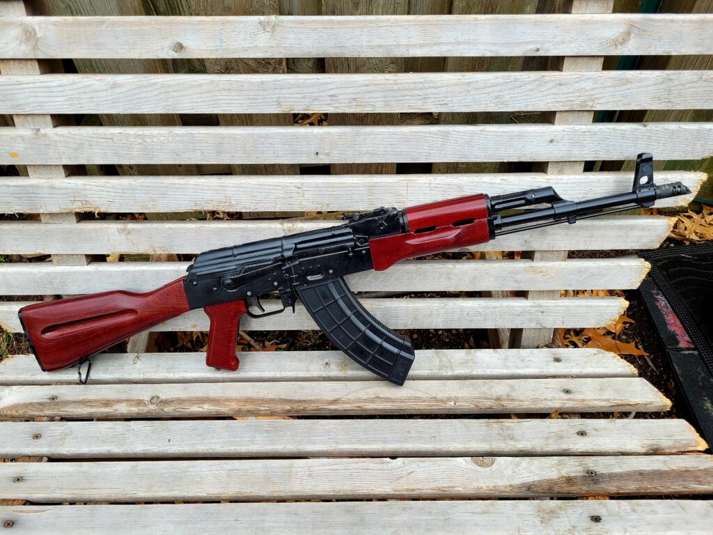
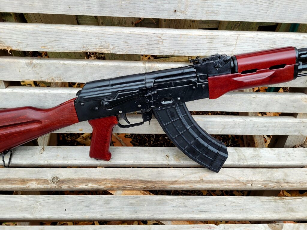
For example, this is Palmetto State Armory’s Redwood furniture set on a Romy G kit I built.

Most of the time with new furniture, you need to remove material and a single cut file works great for that. With the pictured PSA Redwood furniture set, I needed to think the half circle ends of the gas tube cover and I also had to fit the lower hand guard just a tad.

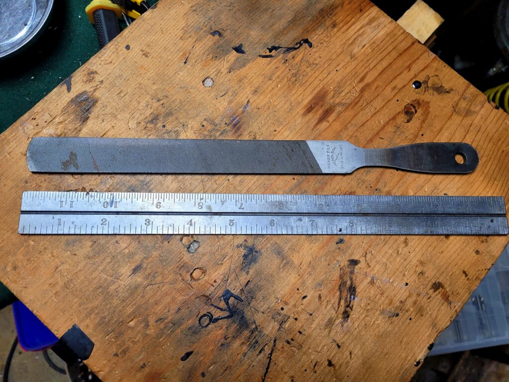
This is an 8″ single cut Nicholson Handy File that I bought many years ago and modified. I prefer a single cut file so I can go slow and not remove material too fast. Just remember an old saying – “it’s easier to take more material off than it is to put it back on.”

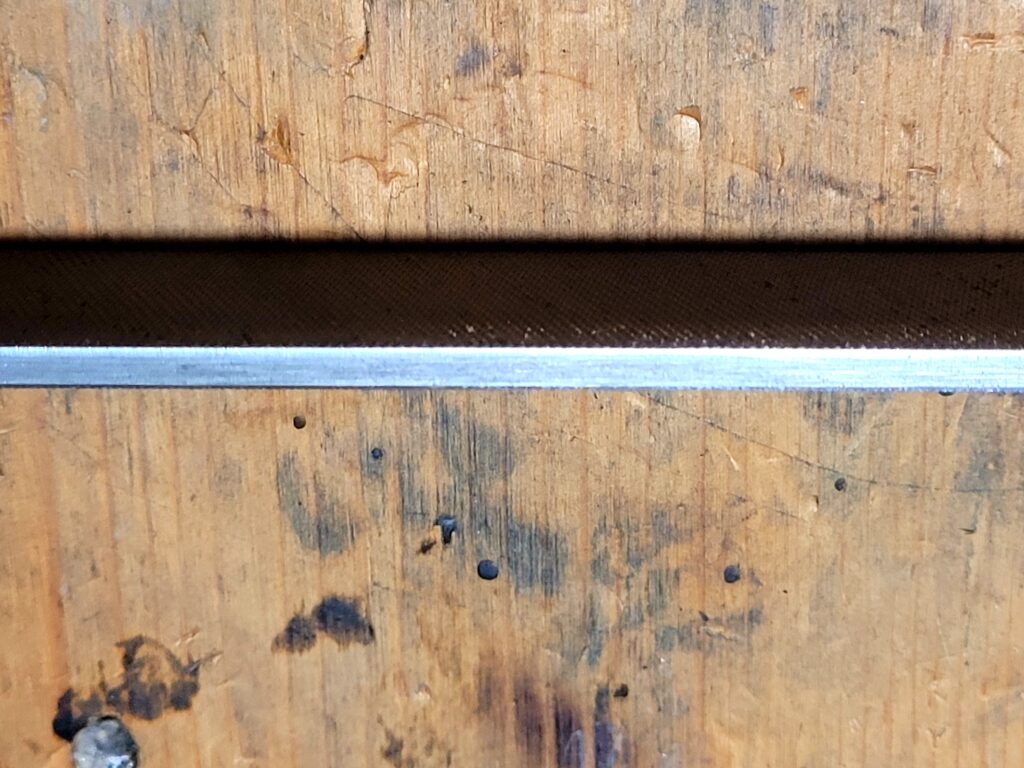
Now here’s the trick to really make this tool work for fitting furniture – grind one thin side smooth – literally get rid of the file’s teeth. This will allow you to quickly and easy run the file right against a raised edge, such as the lips of the gas tube cover, and remove material that you want while leaving the raised edge untouched.

I find an 8″ file just the right size. 8″ is the measurement from the front edge, or “point” of the file, to the base of the heel – the bottom of the main body before the tang starts. The file shown is an 8″ Nicholson Handy File but any 8″ single cut or a file with single cut on one size and double-cut on another would work.

Any brand of file ought to work. Some come with a “safe” edge meaning no teeth. Just test it first to see if any of the teeth from the perpendicular surfaces protrude enough to cut – if they do then knock them down so the smooth surface can ride on the material you are working on with zero cutting happening from that side.

I used my big belt sander and removed all the teeth from this one edge and ensure it was smooth. I purposefully left the teeth on the other thin edge.

Just be patient – look at where the furniture is binding, remove a small amount and test the fit. In general, you want AK furniture to fit snug vs. rattling around. Patience is the key though – don’t rush things. Just keep inspecting, filing off a bit and testing over and over.

So everything is installed, nothing broke because I rushed and the end result is nice snug fitting furniture.

Summary

A single cut file with one thin edge ground is the secret tool but you need to be patient when using it. I can’t even begin to guess how many lower and upper handguards I have adjusted with this file over the years plus I have learned a bit more patience as well.

I hope this helps you out.

I Use A 5.11 Select Carry Pouch To Conceal Carry My Glock 29 Gen 4 When Hiking

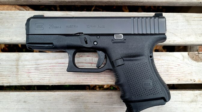
I recently wrote about my Glock 29 Gen 4 and carrying it while hiking. A fellow asked me for more details on what I was using to carry it ands I told him I was using a 5.11 Select Carry Pouch – which is a fancier product name than “tactical fanny pack”. Joking aside, it really does a great job.

Ok, why the fanny pack? I’m on the heavy side and when I go hiking I am usually wearing shorts or sweatpants depending on the weather. Jeans are a “maybe” but I’m at the point in life where I go for comfort. I’m sure not dressing to impress anyone.

If I am wearing jeans and can use a pistol belt then I might use a holster but it depends on the weather. I’d rather conceal the firearm vs. dealing with people staring at my pistol as we are walking along. If I am wearing a coat or open long sleeve shirt then I might wear a belt holster. My preferred option is a Galco shoulder holster.

What I find is that I am often hiking or fishing and it’s too hot for a coat or loose shirt so I had to figure out what to do. I knew a fanny pack might look goofy but would work great if I could find the right one given how it could distribute the weight while concealling the pistol.

The Glock 29 gen 4 is relatively compact but it is not tiny by any means and once you load it down with 10 rounds of 10mm and have a couple of back up mags of 10mm, you’ve got a lot of weight to deal with.

A couple of years ago I ordered in some different models of the no-name import fanny packs that claim to support concealed carry and the quality was very disappointing – light fabrics, lousy sewing and poor zippers across the board. They weren’t an option for the Glock 29 gen 4 because they would never hold up to real world use.

There are a lot of carry options out there but I think I can make the blanket generalization that you get what you pay for – you need a well thought out design, rugged materials, a rock solid zipper and these aren’t cheap.

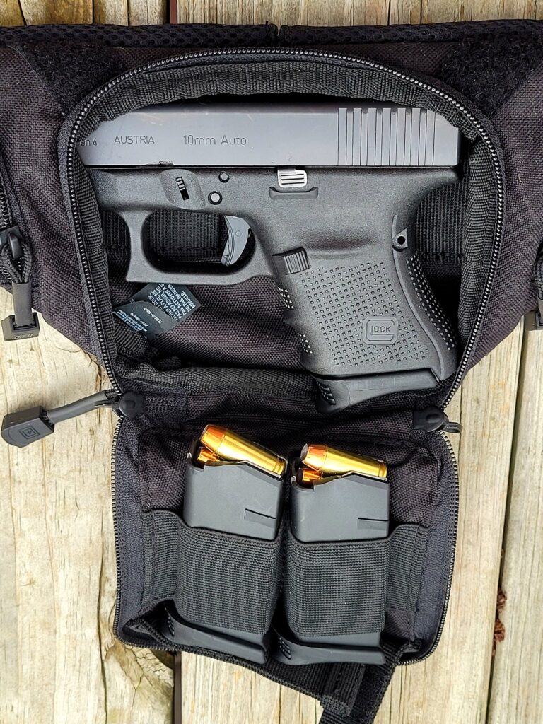
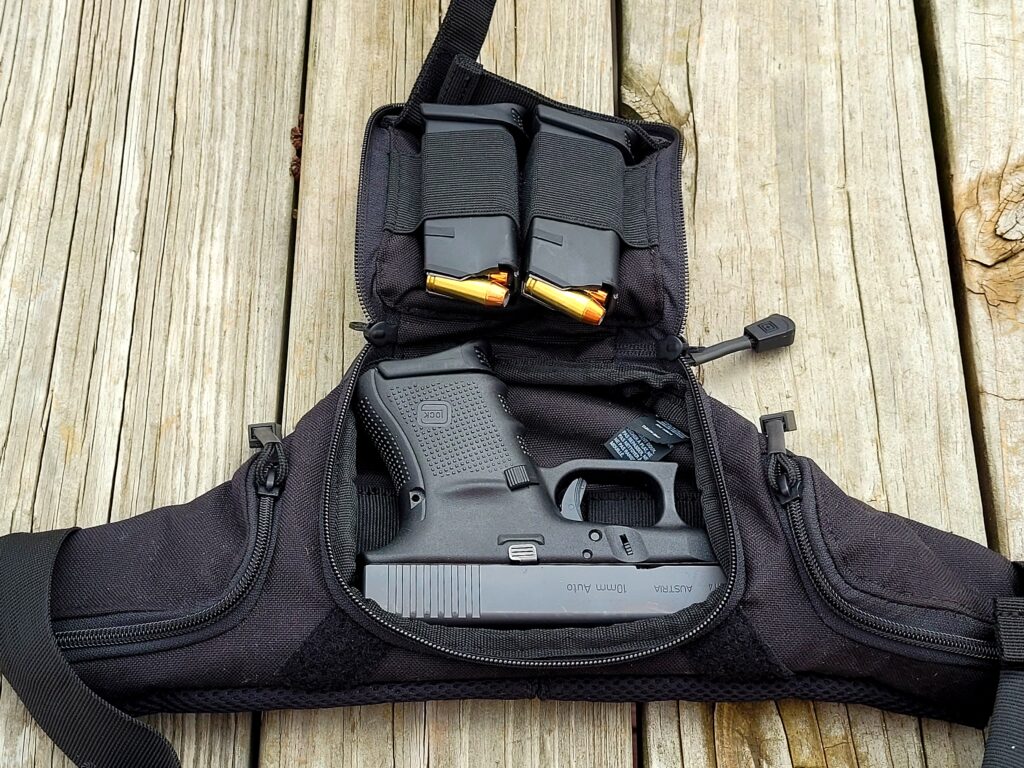
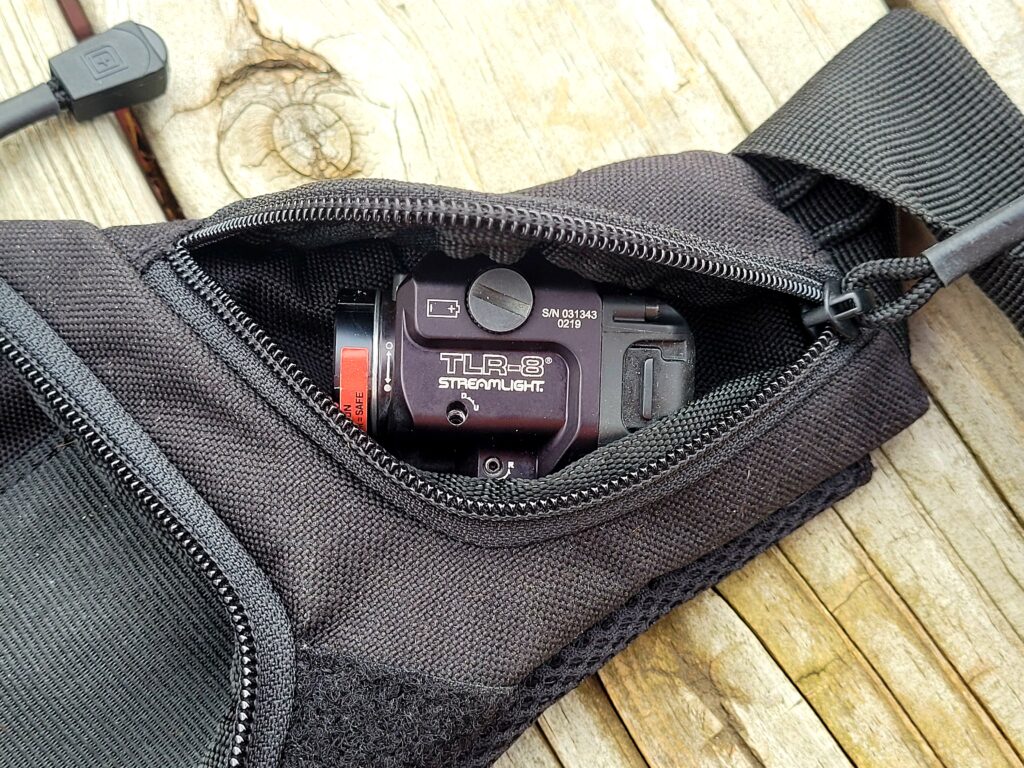
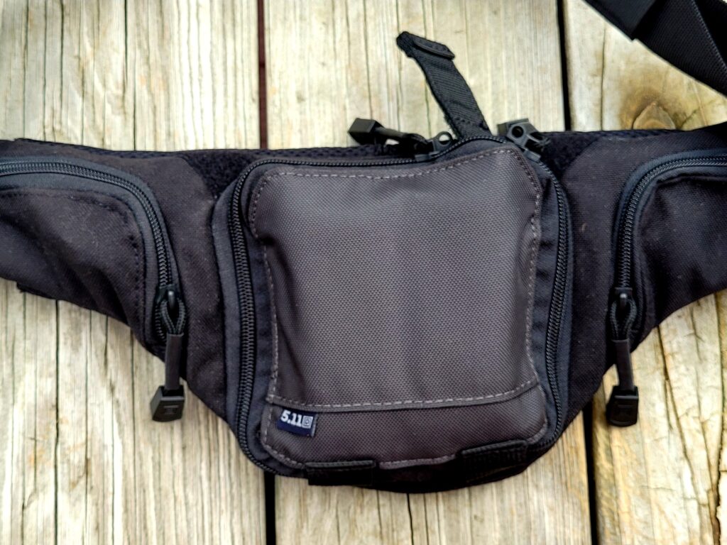
One company I like is 5.11. Their gear is reasonably priced and has never let me down. Yes, I am getting to my point – their 51804 Tactical Select Carry Pouch is very well made, looks good and doesn’t attract attention. It’s a tight fit but I can squeeze in my G29 with the Pearce magazine base plate so I have a place to rest my pinky finger, two more 10 round mags and a Streamlight TLR-8 that I keep in a side pouch.

The main pouch is a tight fit but I can squeeze in what I need. It’s symmetrical so you can insert the pistol facing either left or right. I have mine set up to rip open with the left and pull the pistol out with my right hand.
Here’s another angle. When you have the load shown, there is very little extra space.
I keep a TLR-8 stored in the right side pouch. It’s a snug fit also.
They call that thing sticking up a “hot pull strap” that you can use to yank the compartment open in a rush. Now that folks is one heck of a good idea. If you are in a hurry and the adrenaline is kicking in, fumbling with a zipper is going to suck. Grabbing that pull strap and yanking open the pouch is very do-able.

To give you an idea of real world sizing, a G29 Gen 4 is about 7″ long andjust over 4.5″ with a regular mag. Let’s just round that to 5″ in my case with the Pearce base plates. You can see in the photos that it is a snug fit. My Sig P365 fits no problem.

It works great for me. If you are interested, here’s the link to the pouch on Amazon – click here. Also, here are other sources for you:


Note, I have to buy all of my parts – nothing here was paid for by sponsors, etc. I do make a small amount if you click on an ad and buy something but that is it. You’re getting my real opinion on stuff.

If you find this post useful, please share the link on Facebook, with your friends, etc. Your support is much appreciated and if you have any feedback, please email me at in**@ro*********.com. Please note that for links to other websites, I may be paid via an affiliate program such as Avantlink, Impact, Amazon and eBay.


Seeing The Different Dawson Precision Base Plates For Para P16 and RIA A2 HC 9mm and 10mm Double Stack Pistols

I genuinely like the Rock Island Armory (RIA) double stack 10mm pistols. I jumped into the deep end of the pool and started converting some really cool Mec-Gar Para P16 mags for use in the 10mm and .40 S&W pistols for folks who need either 10 or 15 round limited pistols due to unfortunate magazine limit laws where they live. The feed lips must be shortened and reprofiled to work reliably in RIA double stack pistols.

I’ve written about the conversion and you can click here to learn more but I didn’t really show a lot of photos of the different Dawson Precision base plate options. In addition to changing the feed lips, you have to replace the plate because it literally will not fit in the funnel – it’s a show stopper plus it really does need to be longer to allow for positive seating of the mag in the pistol. You could grind the OEM plate down but then you would need to glue/add material so you can fully set it – note, if you do that, leave a hole so you can unlock the plate in the future.

This post also applies to folks who own the RIA A2 HC double stack 9mm pistols. The same base plates are used on the magazines for your pistols as well and the magazine capacity is limited to 15 rounds as a result.

At any rate, here are a number of photos showing the Dawson Precision base plates and get a better idea of their different thicknesses relative to each other as well as when fully seated in the pistol:

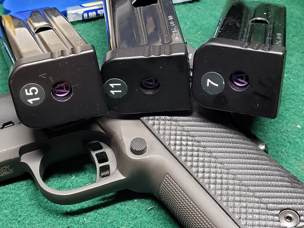
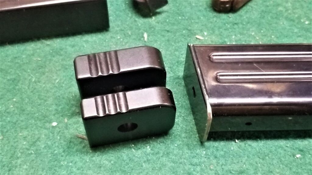
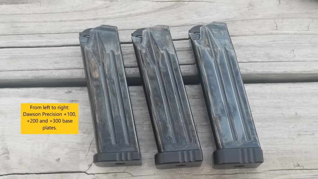
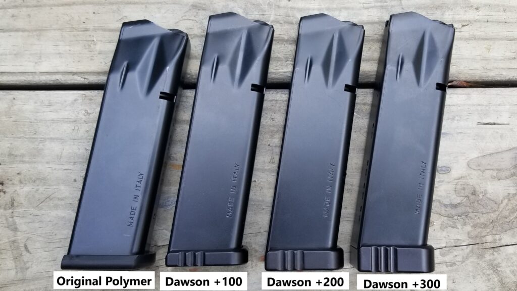
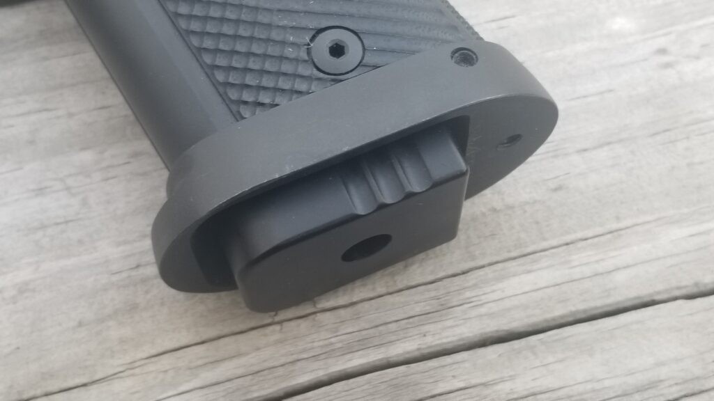
The Dawson plates are machined from aluminum and their sizes are how much thicker they are than the original Para P16 base plate shown on the right. The bottom left Dawson plate is their +200 model and the one above it is the +300.
Here are the three Dawson plates next to each other on our converted P16 magazines. The +100 is on the left, +200 in the middle and +300 on the right. They increase the height and weight of the mag but do not increase the capacity.
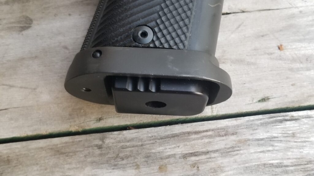
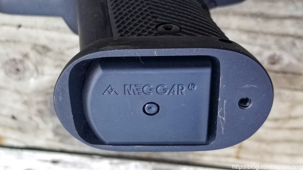
With our 3rd Gen mags, Mec-Gar started using the left polymer plate and it works great in the RIA pistols. Both it and the +100 Dawson plate sit flush in the RIA mag funnel.
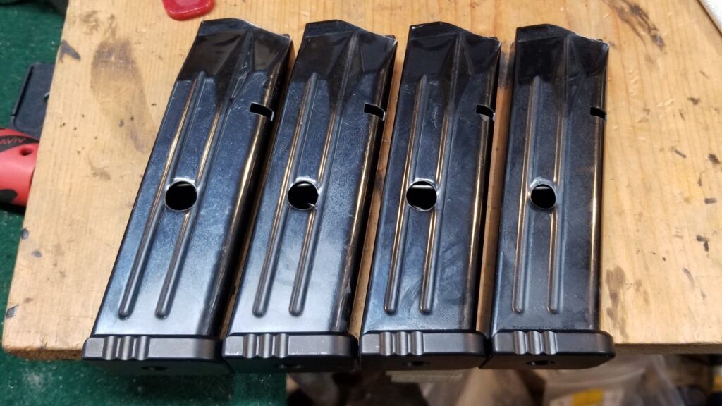
These 15 round windowed mags all have +100 Dawson plates.
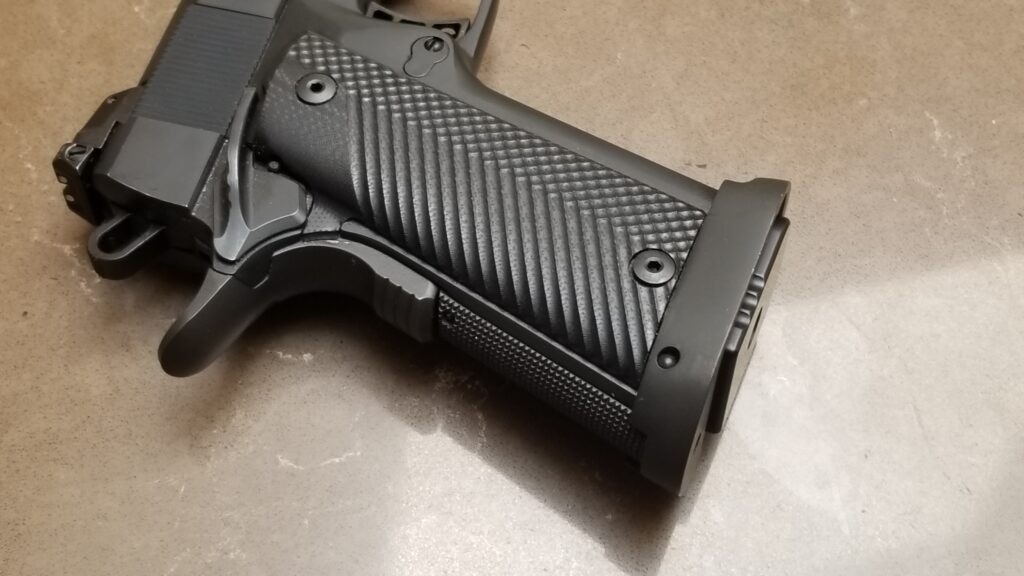
This is a +100 Dawson plate in my RIA 52009 Ultra HC 10mm pistol.
This is the +200 base plate.
This is a +300.
This is the 3rd gen polymer Mec-Gar plate that comes on the 10mm/.40 S&W mags for reference. It fits the RIA funnel just fine.

I do need to note something – out of the two to three hundred converted P16 mags I sold, two buyers had pistols where the distance from the mag catch to the bottom of the funnel would not allow the mags with the Dawson plates to fully seat. I gave them full refunds and don’t know if the issue was the mag catch or the fitment of the funnel to the pistol. Again, only two gentlemen out of hundreds. I really do not think it was an issue with the base plates just to be clear – just stacked tolerances going in the wrong direction.

Summary

Dawson Precision makes great base plates for Para P16 and P18 magazines that enable them to fit in the funnel of most RIA high cap 9mm, 10mm and .40 S&W pistols. They come in three sizes and you can choose based on your preference.

If you would like to purchase base plates or a magazine, please click here to go to the section of our website that has them.

Note, I have to buy all of my parts – nothing here was paid for by sponsors, etc. I do make a small amount if you click on an ad and buy something but that is it. You’re getting my real opinion on stuff.

If you find this post useful, please share the link on Facebook, with your friends, etc. Your support is much appreciated and if you have any feedback, please email me at in**@ro*********.com. Please note that for links to other websites, I may be paid via an affiliate program such as Avantlink, Impact, Amazon and eBay.


How To Locate And Drill AK Front and Rear Trunnion Rivet Holes

Building an AK takes a fair amount of drilling, fitting and riveting that can intimidate someone thinking about building their first rifle. Lucky for them, the industry has evolved a lot of really cool tools exist to enable faster higher quality results. A good example of evolution is the location and drilling of the the rivet holes in the receiver for the front and rear trunnions.

Back around 2006 or so when I got started, you either measured the location of the trunnion holes and marked them or you could take a post it note, push it on the trunnion to get an outline of the holes and then transfer it to the receiver, again marking where to drill. You learned quick to start with a small drill bit so you could adjust a bit if you were off with either method – I got pretty good with the post it note method actually.

One of the AK-parts and tool vendors that has been around the longest is AK-Builder and he was always bringing new offerings to the market, I slowly added one of all of his tools as funds permitted. I had his rivet jig, flat bending jig, the top rail layout jig (if you remember those) and so forth. At some point he added a really, really cool jig for locating and drilling the holes for the trunnions. I bought it and swear by it to this day.

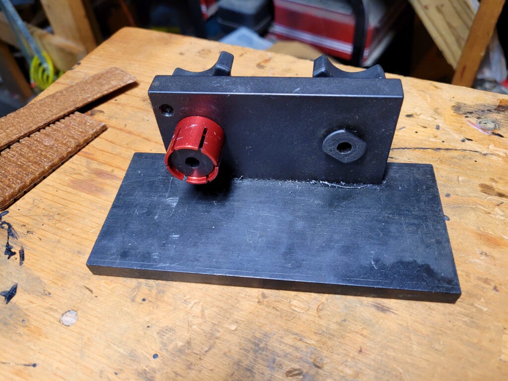
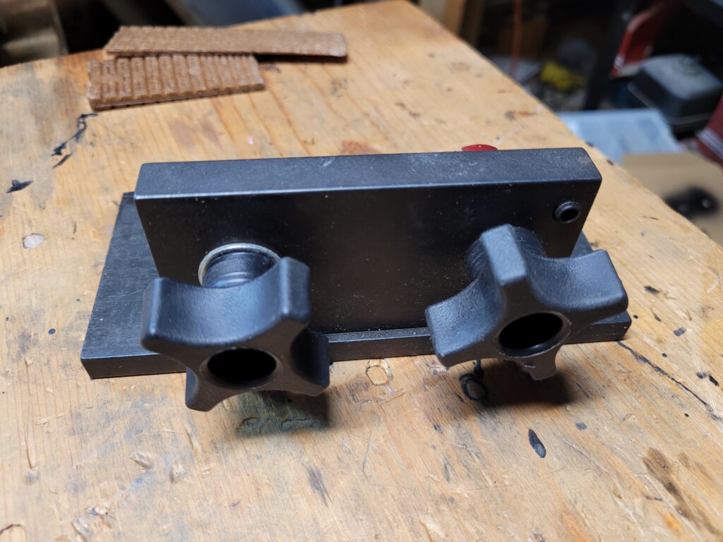
The jig is extremely well made and durable. When you buy it, you have options for the sizes of mandrels to fit different barrel channel holes. The red one you see works on 7.62 AKs and they also have one for 5.45 and the unique MAK90. The rounded rectangle on the right holds the rear trunnion.

Using It For The Front Trunnion Holes

Using this fixture is about as easy as it gets but you must have a drill press. I’d recommend an X-Y table on your drill if you plan to do this much but at least have a drill press.

  1. Securely mount the fixture to your drill press.
  2. Insert the trunnion and tighten the knob so it can’t move.
  3. Move your drill table around to line the drill bit up with the hole in the trunnion.
  4. Slide the receiver over the trunnion.
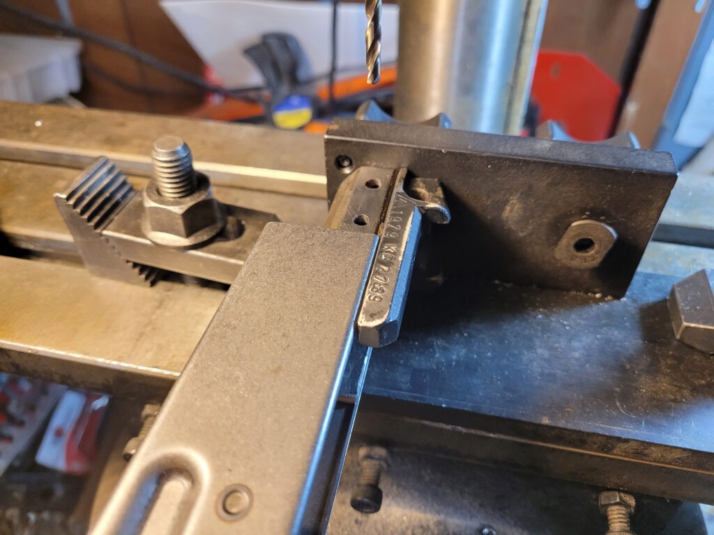
  5. Lower the drill and it will go in the exact same location as the trunnion hole you lined up on.
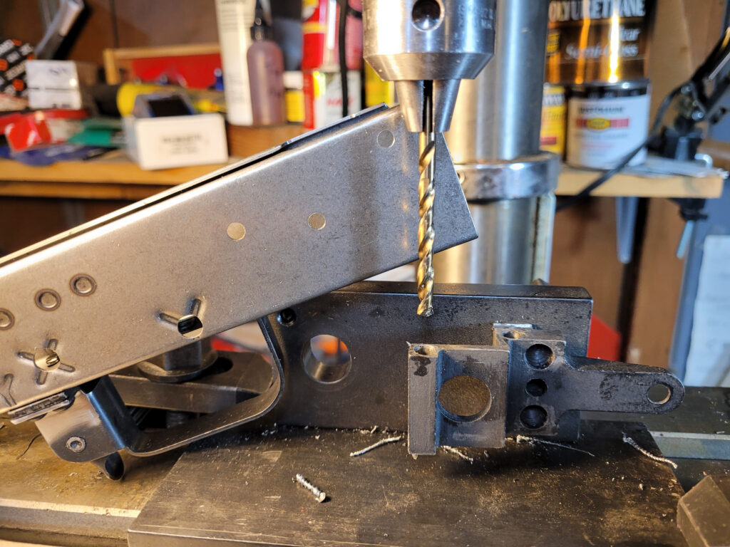
The front trunnion is being held securely by the fixture. I am sliding the receiver forward and when I bring the drill down, it will make the hole in the exact same spot as what was in the trunnion.
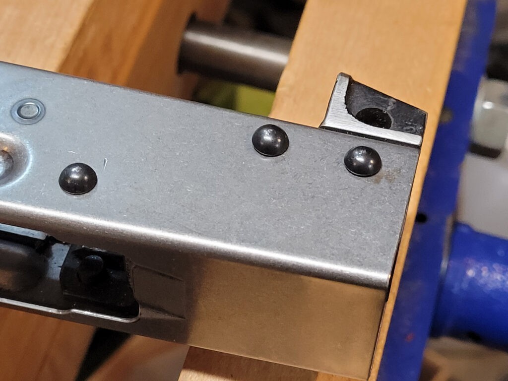
This fixture is the best means I have found to quickly and accurately locate and drill the trunnion holes in the receiver. I prefer undrilled receivers because with this jig I can put the holes exactly where I want them. By the way, these are AK-Builder rivets also.

Tips For The Front Trunnion Holes

  • Confirm the drill bit sizes you need before you start. For most AKMs, the front rivet holes are 4mm so you can use either a 4mm or 5/32″ (3.868mm) bit. Note, that dimension can be different so just confirm is my point. Also, I’d recommend good cobalt bits personally.
  • Use cutting fluid – I like Tap Magic personally.
  • You will drill a hole at a time – do not try to go all the way through. Small alignment errors become big problems when you do that. Avoid the grief – do a hole per rivet.
  • Make sure the table can’t move, that the fixture is secure and that the trunnion is being held firmly. If anything moves, you are hosed.
  • Line up on the hole, slide the receiver all the way on, pull it back just enough to verify nothing moved one last time.
  • After I drill the first rivet hole I carefully inspect everything is lined up. I then move to the second rivet hole and repeat the above but before I drill, I insert temporary rivets in the holes to make sure nothing moves. DO NOT SQUISH THEM – I literally am just using their bodies to keep everything lined up. It really helps avoid small movement errors.
  • If you mess up real bad for some reason, weld the hole shut and start over.
If you go to the AK-Builder product page for this jig [click here] you should note the link in their description to a page with a lot of photos and detailed instructions.

Doing The Rear Trunnion

Doing the rear rivet holes uses the other side of the drilling jig. The little rectangular tab goes into the top of the rear trunnion where the recoil spring rod normally sits and you can then crank it down tight to hold it in place while drilling.

Notice the receiver will be parallel to the jig during these operations. Again, make sure everything is secure and you need to make sure the back of the receiver is true to the rear of the trunnion.
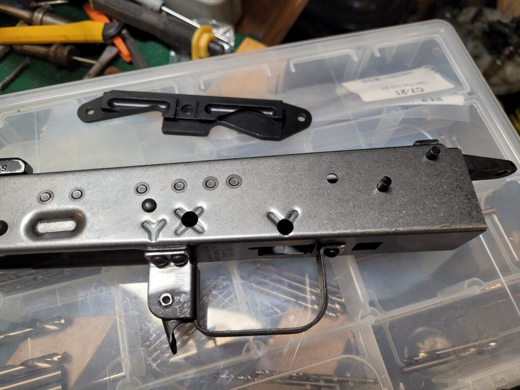
The end result will be accurately located holes. Before you set the rivets, this is when you should be thinking about a side rail for optics if you want one. I like the AKM side rail mount from AK-Builder. Those holes you will need to manually locate and drill. Use a caliper and true the top of the rail to the top of the receiver if you do install one.

Tips For the Rear

  • First, read all the tips I wrote for the front trunnion if you skipped them.
  • The key to all of this is a solid setup and nothing moving.
  • Confirm the size drill bit you need. It will probably be 4.5mm which you can do with that size drill or be close with 11/64″ (4.365mm).
  • DO NOT DRILL STRAIGHT THROUGH. I’d recommend you take your time and do a hole at a time.
  • Once you get a hole drilled and are ready to do the next, stick a rivet in it to prevent movement.

Summary

The AK-Builder drilling jig is the best tool I know to help you quickly and accurately locate and drill the front and rear trunnion holes in your receiver. I definitely recommend it.


Note, I have to buy all of my parts – nothing here was paid for by sponsors, etc. I do make a small amount if you click on an ad and buy something but that is it. You’re getting my real opinion on stuff.

If you find this post useful, please share the link on Facebook, with your friends, etc. Your support is much appreciated and if you have any feedback, please email me at in**@ro*********.com. Please note that for links to other websites, I may be paid via an affiliate program such as Avantlink, Impact, Amazon and eBay.


How To Quickly Remove AK Receiver Rivets

Okay, there are a ton of ways to remove rivets and I’ve posted some details both about removing the trigger guard and side rail rivets (if your AK has a side rail). This post is going to get straight to the point.

I use a 4.5″ cordless Ryobi angle grinder and take all the rivet heads down flush. Unless I plan to reuse the receiver, I don’t care how the receiver looks when I’m done. If I do care, then I will be much more careful and stop just before I get to the surface.

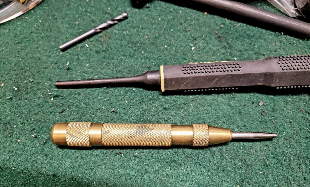
I then center punch all of the holes to make drilling easier. I like to use an automatic center punch so I can focus on where I want to make the divot for drilling vs. trying to keep everything aligned. If you’ve never used one, they are worth their weight in gold.

I drill an 1/8″ hold in each one use quality cobalt drill bits and cutting oil. I like to buy Tap Magic in bigger containers and then transfer the fluid as needed into smaller squeeze bottles with long metal tubular “needle” tips so I can precisely put it right where I need it.

From the top – 1/8″ drill bit, roll pin punch and an automatic center punch on the bottom.

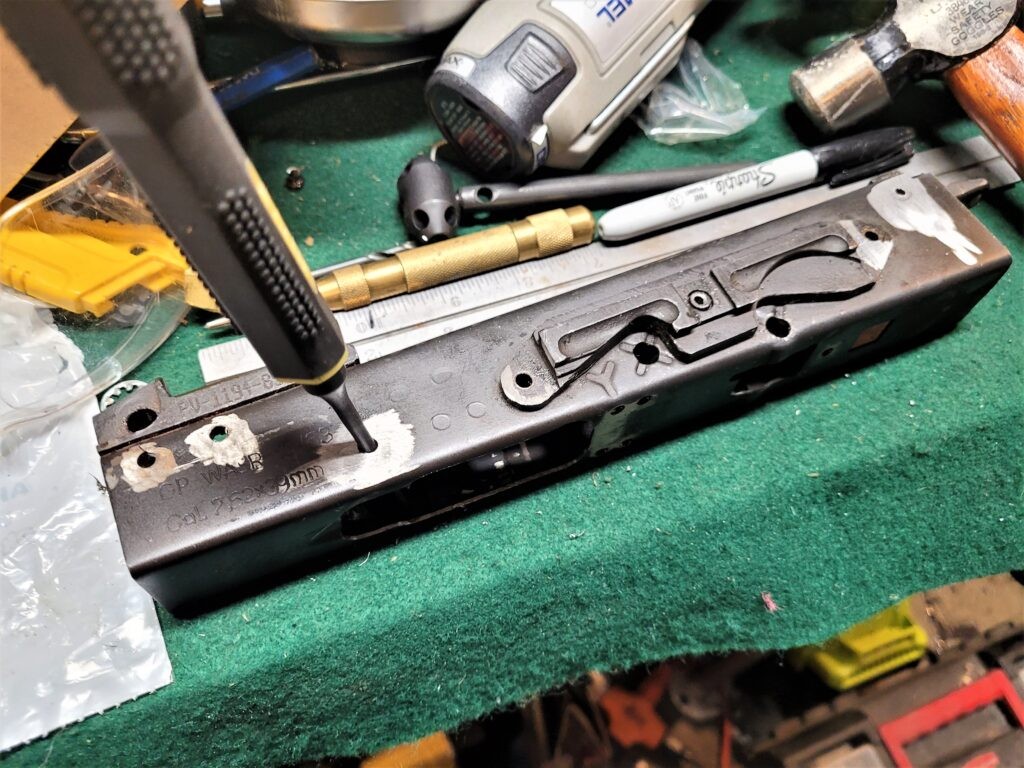
I then use a roll pin punch where the rounded tip can fit in the 1/8″ hole and the shoulder properly engage the remaining rivet. Folks, this makes removing the remaining rivets super easy except for the long trunnion rivets.

For the short rivets, I like to drill them out with an 1/8″ bit to both create a hole and relieve stress. I then use a roll pin punch to easily knock them out because the ball end of the punch keeps it centered on the rivet. If you’ve ever fought with keeping a normal punch centered while hammering, a roll pin punch centered in a hole makes a night and day difference.

Long Rear Trunnion Rivets

Okay, these take more work so we’ll make a section just for these little headaches. They’re not horrible – they just take additional time to remove but I will tell you a HUGE time saver in a moment.

In general, it’s easier to remove the rivets with the trunnion out of the receiver. If you need to save the receiver, be gentle and use successively larger drill bits to remove the rivet heads so you can then pry the sheet metal receiver open and pull it out. The balancing act is that if you make the receiver holes too big then you will need to weld them shut and drill new ones. It’s not the end of the world. I prefer welding and redrilling compared to using even bigger rivets with heads that cover the holes but are mismatched to everything else.

If you don’t care about the receiver or are removing stubs, grind those heads down and use an air hammer chisel to easily bend the receiver sheet metal away from the receiver.

With the rivet heads ground off you can clearly see the rivet body outline and thus you can mark the center.

Traditional Method – drill in from each side about 1/2 way and then punch the rivet out. Guys will use 5/32″ (3.969mm) or even 11/64″ (4.366mm) drill bits. If you are spot on the center and you have access to quality cobalt metric bits, this is usually a 4.5mm rivet so you could use that. You will read about guys suggesting 3/16″ drills but this route is problematic because 3/16″ is 4.762mm and thus too large. You’d need to use a 3/16″ rivet to properly secure the trunnion and the heads will look noticeably different from the others.

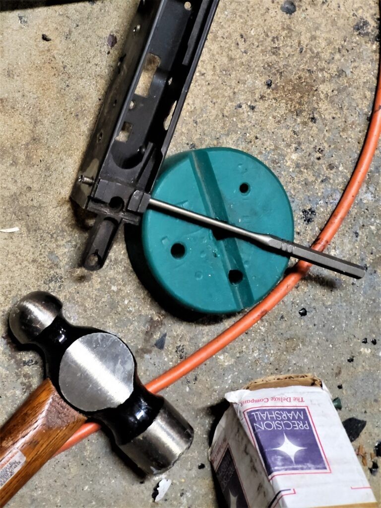
Old school – drill the rivet out most of the way and then punch it out the rest. You can see the pin exiting to the left. Note, do this on a hard surface that isn’t going to flex and absorb some of your blows. Here I am literally beating the crap out of the punch on the concrete floor. I’ve since moved on to a method using an air hammer that I will describe next.

The impatient Ronin method – drill 1/8″ centered holes in one side of the rivets left in the trunnion. Make or buy an 1/8″ air hammer drift pin and chase each long rivet out in a matter of seconds. It’s amazingly fast. I don’t know who invented the air hammer but it is seriously magical when it comes to tasks like this.

I can pop out a rivet in seconds using an air hammer and my rivet fixture. I took two old .401 shank air tools and drilled center holes. One is 1/8″ and the other is 5/32″. I then have a variety of lengths of 1/8″ and 5/32 dowel pins to do the job. I built both diameters but really I just use the 1/8″ punch now. I put the trunnion in a heavy metal working vise and start with a short pin to start the push and then a longer pin to chase it all of the way out. It works like a dream. If you do this, please, please, please wear safety glasses. A hardened dowel pin can brake in these situations. For an air hammer, I am using an IR 116 – a 4x air riveter ought to work also, I have a 3x ATS but have never tried it for this.

Summary

Use an angle grinder to knock off the rivet heads, drill and punch out the short rivets. For the longer rivet, decide which of the two methods you want to use. I hope this helps you out!


Note, I have to buy all of my parts – nothing here was paid for by sponsors, etc. I do make a small amount if you click on an ad and buy something but that is it. You’re getting my real opinion on stuff.

If you find this post useful, please share the link on Facebook, with your friends, etc. Your support is much appreciated and if you have any feedback, please email me at in**@ro*********.com. Please note that for links to other websites, I may be paid via an affiliate program such as Avantlink, Impact, Amazon and eBay.


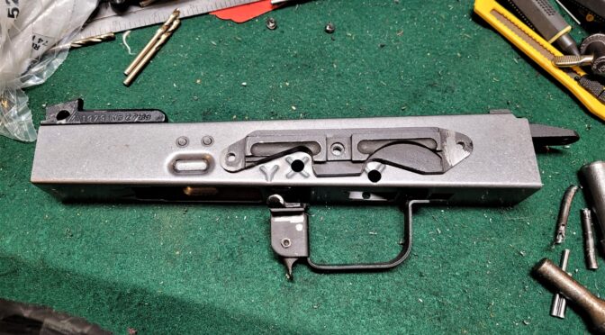
You can Easily Remove A Side Rail Scope Mount But The Receiver Is Going To Look Butt Ugly

The Kalashnikov design team took an interesting approach to mounting scopes on AK-Rifles. Rather than centering the optic over the bore they placed a mounting rail on the side of the receiver. There are different types depending on the model of rifle in question but one thing that pops up from time to time is whether one can be removed.

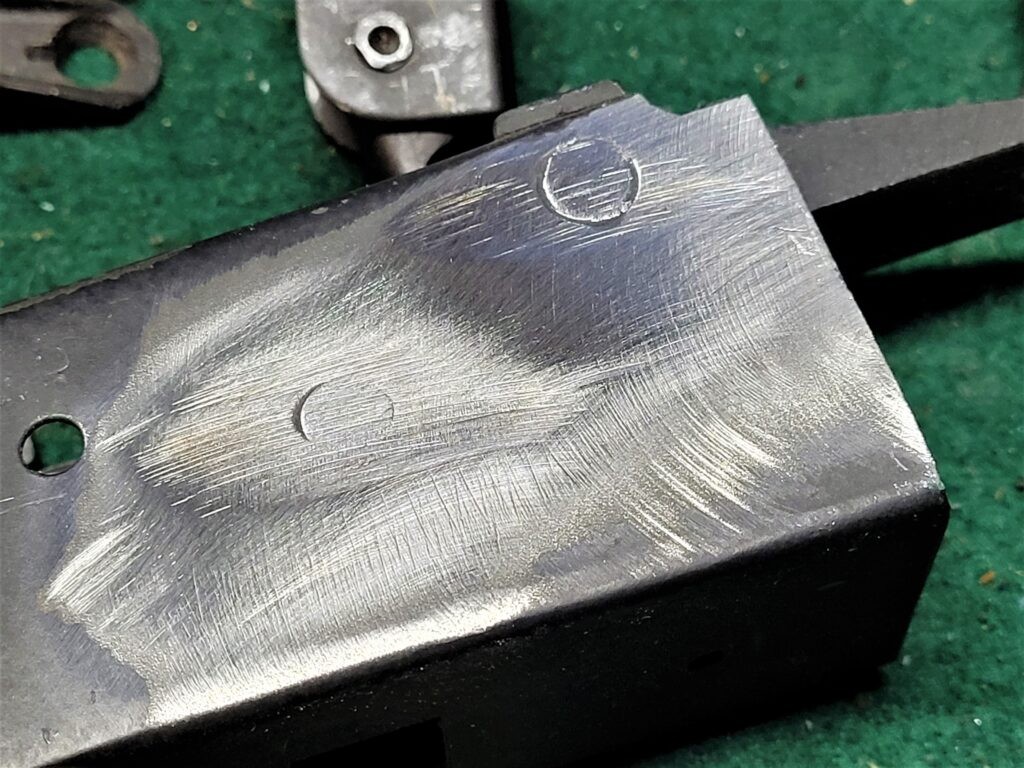
The short answer is yes. Now I add in the “but” – it is going to leave you with a receiver that not only has holes in it but receiver material that was forced into a countersink so you will have at least the center rivet area on the sheet metal receiver that will probably stick out like a little volcano taunting you.

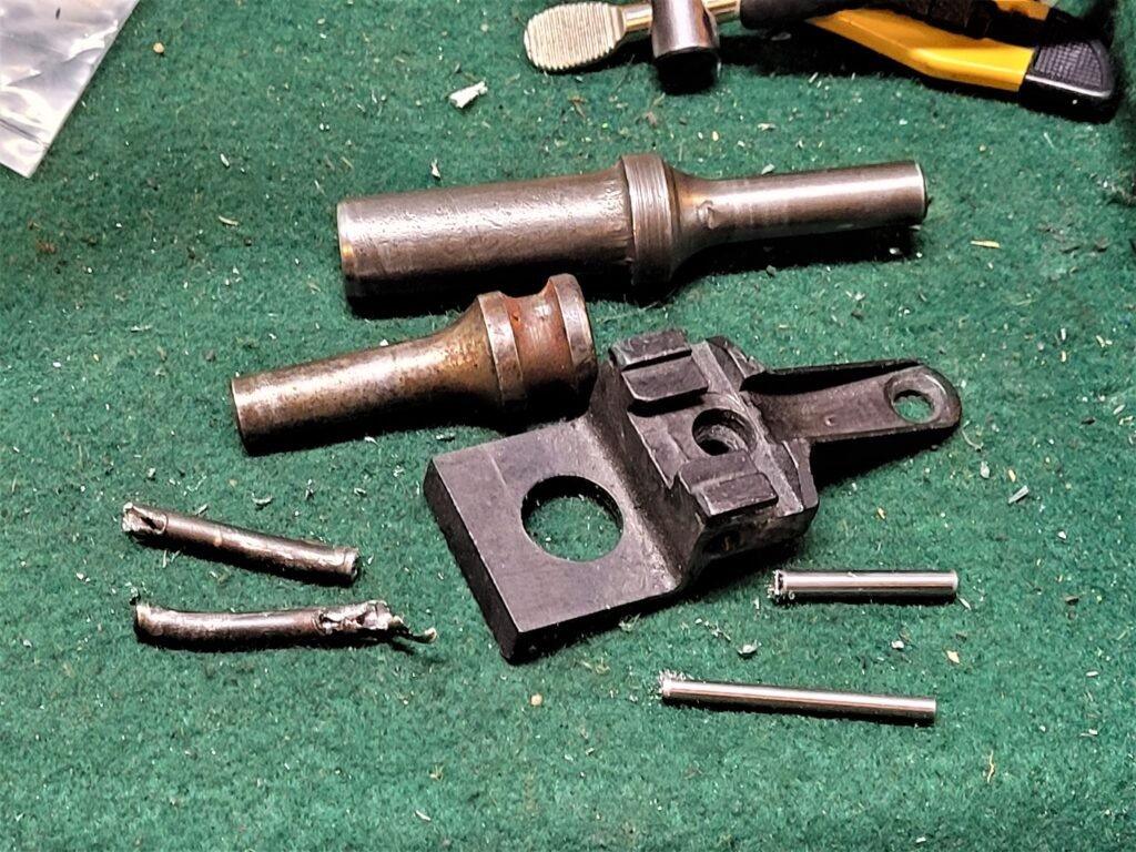
Center punch and drill out the rivets. The rear rivet is an it depends – it may either be short like you see with the AK-74 or attached via the long rear trunnion rivet. You may want to start with an 1/8″ drill and go up to 5/32″. The rear trunnion if it has a large rear trunnion rivet in it will be 4.5mm and I actually use a 4.5mm cobalt bit on that one to free up the side rail. Some guys who don’t have a 4.5mm bit will use an 11/64″ drill bit instead – it’s 4.366mm. I’ll do another post about trunnions but unless you are running a drill or mill that you know is true to the table and work piece, do not try and drill the rivet out entirely from one side, I go about half way in from each side and punch out the remainder or use an air hammer to chase out the rivet with an 1/8″ drift pin but that’s a topic for another day.
You can see the receiver material that was forced into the center hole. It really shows how secure riveting can be with countersunk rivets and holes.

So, yes, you can drill out the rivets and use the scope mount on other rifles. The question becomes what to do with the source receiver. If it is getting destroyed then this is a non issue – follow whatever your procedures are to file a destroyed receiver/firearm record with the ATF provided it was serialized and registered to begin with unlike rifles built from a blank, etc.

Now if you want to keep the receiver, the recommeendation would give is to put a thick copper backing plate behind the holes, weld them shut and then sand the result flush. For the holes with the cones, if you have any, grind/mill them down flush first and then do the same – copper backing plate, weld the holes shut and then sand flush.

You’ll need to refinish at least the receiver and the bluing on the steel welds typically doesn’t blend with bluing on the receiver so you may want to just refinish the whole thing if you care about it looking good.

Looking at the back of the side rail is fascinating. The whole indexing of the scope rail starts with the front rivet of the rear trunnion. and then having an equal distance from the top of the receiver to the top of the side rail. Now this one is flopped 180 degrees compared to the receiver under it but look at the accomodations they have for thee selector lever and center support pin of the receiver. This is off a WASR-10 and is an AKM style plate but interestingly the rear trunnion was a split AK-74 style with two small short rivets in front on the two legs of the trunnion and a long rear trunnion vs. the ccommon AKM approach of two long rivets securing the rear trunnion. The machining is crude but it did the job. The AK-Builder plates are virtually identical but far better machined and finished. If I needed to use an AKM side rail, that’s what I would get.

Summary

Yeah, you can remove the side rail but if you plan to continue to use the receiver, you’ll need to weld the holes closed, sand, and refinish the weapon. I’m very impressed by the design they came up with – it spreads forces across the sheet metal receiver and allows ready access to the dust cover and internals if required.


Note, I have to buy all of my parts – nothing here was paid for by sponsors, etc. I do make a small amount if you click on an ad and buy something but that is it. You’re getting my real opinion on stuff.

If you find this post useful, please share the link on Facebook, with your friends, etc. Your support is much appreciated and if you have any feedback, please email me at in**@ro*********.com. Please note that for links to other websites, I may be paid via an affiliate program such as Avantlink, Impact, Amazon and eBay.