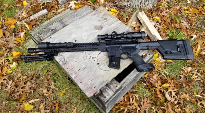
Category Archives: Firearms Building and Gunsmithing

How to build and/or gunsmith on certain platforms.

PSA AK-V Part Three: Changing the Brace, Adding a Red Dot and Installing A Quick Takedown Pin For The Dust Cover

Out of the box, the AK-V is impressive. The trigger is decent, the grip and handguard are functional but there were three things I really wanted to do – move to a SBA4 brace, install an optic and create a quick takedown pin so the dust cover could be removed (the big reason I bought the AK-V from a business perspective). So let’s step through each.

Palmetto State Armory (PSA) has a stunning array of Kalashnikov firearms now. AK-47s, AK74s, 100 series, rifles, pistols … it’s impressive. Click here to go to their main AK menu.

Replace The SBA3 Brace With An SBA4

Yes, they are both adjustable braces but that comparison ends there. The SBA4 is much more sturdy and has five length of pull adjustment positions. The SBA4 does go on sale and that is the time to buy one. I got mine for $99 at PSA’s July 4th sale and there was free shipping!

The SBA4 is the top brace and the SBA3 is the bottom. You can instantly see the SBA4 has more bracing and is bulkier. The back end does not flop around either unlike the SBA3.

Now PSA did something with the SBA3 that is a best practice. They staked the castle nut to the receiver end plate. Now, I started thinking about what would be my easiest option and it dawned on me that if I was SB Tactical and wanted to control cost and complexity, I would try and have as few inventory parts as possible and that means as few buffer tubes. Guess what? The SBA3 and the SBA4 both use a Mil-Spec 6 position buffer tube. Problem solved. You can remove the brace just like most AR/M4 stocks – lift up on the locking pin and slide it right off.

The Castle Nut has two real solid stakes in it. Kudos to PSA.
Ta-da! Under the brace is a Mil-Spec buffer tube or “receiver extension” depending on who you talk to. The SBA3 and SBA4 use the same tube!! Note, the weapon is upside down for this photo.
Here’s a good shot of the receiver. See that small vertical slider switch just above the mag catch? That’s the bolt release. The M4 buffer tube / receiver extension they are using is rock solid. If it is made by someone else, I don’t recognize it.
Here’s the tail end of the SBA4 on the left vs. the SBA3 on the right.
The SBA4 uses the same buffer tube and slides right on in place of the SBA3 brace.

The result is a very sturdy brace. After comparing the two, I will only use SBA4 braces going forward.

Vortex Crossfire Red Dot Optic and American Defense Mount

I doubt I will ever go past 100 yards with the AK-V and a much more likely engagement distance is 50 yards so a red dot is perfect. I’m a huge Vortex Optics fan and this was a perfect situation for their Crossfire Red Dot mounted on an American Defense AD-T1-L STD quick detach mount. They are my favorite combination of price and performance these days.

By the way, be sure to keep a couple of spare 2032 Lithium batteries in your case or range bag. Nothing dampens a range trip like dead batteries. It’s also why I use a quick detach mount – if the batteries are dead or that optic fails, I am yanking that optic off.

With the AD-T1-L STD mount you are a tad higher than the AK-V’s sights. I plan to watch how they relate at the range so I can ballpark where to aim if the battery is dead and am in a rush. Practice, practice, practice and not just when everything works.

Here’s the Vortex Crossfire Red Dot on the American Defense AD-T1-L STD mount. If you wonder why I use American Defense, it’s for the quality. Cheap Chinese/import quick detach rings shoot loose, don’t return to zero and bend/break over time. AD stuff is rock solid made from aerospace aluminum. Note, you can see our Quick Takedown Pin just above the handguard and I’ll cover that next.

The AK-V Dust Cover Quick Takedown Pin

I had to look up — I built my first Yugo M92 in 2012 and instantly hated the hinged dust cover. I drilled out the rivet and came up with a stainless pin with a ball detent and pull ring to secure the cover. The rest is history. I wound up making pins for the M92/M85, Tula and Bulgy Krinks use the same pin, Vepr shotguns and now the AK-V.

The reason for wanting a quick takedown pin is plain and simple, when you want to clean the weapon or work in the receiver, the hinged dust cover is in the way. To remedy this, you can install our AK-V quick pin and it’s about a 10 minute job if you know how to strip down an AK. This is a quick overview:

  1. Ensure the weapon is empty.
  2. Field strip the weapon like you would any AK, remove the gas tube and the lower handguard so they are out of the way. 
  3. The AK-V’s hinge is simply a 5/32″ roll pin that needs to be tapped/punched out so use something like a bench block to support the weapon and create a hole/gap for the pin to exit into.
  4. Use a 5/32″ roll pin punch and a hammer to tap the roll pin out.  You can save it for the future in case you ever want to use it again for some reason. 
  5. Put the dust cover back in place with the hinge holes lined up and slide in our quick takedown pin.
  6. Re-assemble the weapon.
  7. Done
Here, I have the rear sight block fully supported by the bench block behind it and am using a 5/32″ roll pin punch and hammer to drive the roll pin out.
What makes a roll pin punch different from a normal punch is the dome in the middle that centers the punch on the pin and makes driving the pin out very easy. It also reduces the risk of a regular punch slipping off what you are working on an scratching the finish.
So this is what you wind up with once the roll pin is removed.
This was my first attempt because I am right handed. Having the pull ring there right next to the gas tube locking lever was just too much. I flipped it around and had the pull ring on the other side of the gas block.
This is how I am running it now. The pull ring is on the left / non-operating side and the ring is tucked just behind the handguard.

We have the pins up for sale on our website now. Click here to order one.

Summary

Looking good!

The AK-V was almost done at this point. I still needed to lubricate the weapon and put it in a suitable case. I’ll tell you about that part of the journey in the next post.


This is a four part series on the PSA AK-V 9mm:


Note, I have to buy all of my parts – nothing here was paid for by sponsors, etc. I do make a small amount if you click on an ad and buy something but that is it. You’re getting my real opinion on stuff.

If you find this post useful, please share the link on Facebook, with your friends, etc. Your support is much appreciated and if you have any feedback, please email me at in**@*********ps.com. Please note that for links to other websites, I may be paid via an affiliate program such as Avantlink, Impact, Amazon and eBay.


Great Animated Video That Shows How A Glock Pistol Operates: It Really Clarifies Things!

As the saying goes, a pictures is worth a 100 words. Well, this video is worth a few thousand. I am very, very impressed by the fire control group that Gaston Glock created with the three integral safeties. In talking with a lot of Glock pistol owners, they aren’t very clear on how the pistol operates and now I can share this video with folks.

This example screen shot from the video shows how a case is extracted and then ejected. The level of detail is exceptional. Note how the creator of the video shows you a faint ghost image of the pistol around the components he is demonstrating.
In part of the video, the creator shows you how all three safeties work. The above screen shot is from the part of the video where the firing pin safety mechanism is explained.

Matt RIttman created this animated video and really did a service to the firearms community. The computer animation is excellent and the operation of a Glock 19 Gen 4 is very clear. This is a must see for any Glock or Polymer80 owner. I’m not a huge fan of Glock pistols but I am of pistols with the Polymer 80 frames/receivers because of the grip angle. I’ve now built two and legally registered them in Michigan.

Here’s the Video

It’s only 2:54 long and totally worth your time:

I hope you find this as interesting as I did.


If you find this post useful, please share the link on Facebook, with your friends, etc. Your support is much appreciated and if you have any feedback, please email me at in**@*********ps.com. Please note that for links to other websites, I may be paid via an affiliate program such as Avantlink, Impact, Amazon and eBay.


What To Do When Your AK’s Barrel Is Too Big For Your Front Trunnion?

A few years ago, I bought a 1969 Polish Radom Circle 11 AKM kit from Arms of America. It has laminate furniture, matching parts and they populated a new Polish Chrome Hammer Forged (CHF) barrel with the front, gas and rear sight blocks. Furthermore, it was headspaced. I double checked that before I pushed out the barrel pin and then the barrel – that’s where things got interesting.

Pressing Out The Barrel

I have a 30 ton H-style hydraulic press with a 20 ton air-over-hydraulic bottle. The thing is a brute and have used it many, many times over the years on gun and car projects. There are a few things you learn over the years – 20 tons is 40,000 pounds and is a serious amount of pressure – steel parts can bend, break or even shatter under those loads. You learn to go slow, watch carefully feel the pump and listen. I also learned long ago to use the air to move the ram quickly but always do the real work by hand for those very reasons – I’ve bent the crap out of stuff in years past because you can’t tell what is going on.

I wear a full face shield when working with a press. I’m not joking when I say things can go bad fast when there is a lot of pressure. When you push out a barrel, you just don’t expect a ton of pressure from a new kit – at least I don’t. I’ve had some real hairy barrel pins and barrels in years past when dealing with surplus… but not on a new kit with a populated barrel … not until now.

Pressing Out the Barrel

As you can guess, the barrel did not press out easily. I had to apply a boatload pressure – way more than average. So much that I put a 3/4″ piece of plywood between me and the trunnion/barrel assembly. I was also checking and double-checking that my barrel press tool squarely on just the barrel and not a part of the trunnion – guys I was nervous.

I reached the point where I knew I was squarely on the barrel and something had to give. I was whacking on the press trying to shock the barrel out and I kept upping the pressure – pump, whack, pump, whack… Finally the barrel came free like a gun shot. Guys- do you remember the old Romy kits where the pins and barrels sometimes felt like you were taking your life into your own hands? That’s what this felt like.

I actually inspected the front trunnion very carefully looking for cracks. I then inspected the chamber end of the barrel – nice and smooth – remarkably smooth. No signs of galling. Ditto on the inside of the trunnion. I suspect that someone was using some kind of press system that included a barrel support and slammed that new barrel in using a level of force I couldn’t do without damaging parts. I noted to myself that reassembly was probably going to be just as colorful.

Building The Kit

Nothing new about building the kit – I had fun. In the below photo, the front trunnion and rivets are just sitting there. I was mocking things up and they are not actually set. I installed the trigger guard taking care to orient the selector stop properly and using a rubber band to keep the assembly together as I used my press and an AK-Builder trigger guard rivet jig to do the job.

The rubber band keeps the receiver down on the trigger guard jig so the rivet, selector stop and trigger guard all stay in place while you move around. The AK-Builder jig really does a nice job.
Here, everything is drilled and seems good to go.

So let’s get back to the main point of this blog post and why you are probably reading this – what do you do when the interference fit is too tight and the barrel will not go into the trunnion all the way.

Life Got Colorful Trying to Press The Barrel Back In

Yeah, that tight fit came back to haunt me. I tried polishing the trunnion and applying non-seize. Usually this works for me but when I went to press the barrel back in, it would not go. I saw the barrel begin to deflect in the press and immediately stopped. Let me explain what I mean by deflect – a material will bend so much and spring back into place. When I saw the barrel begin to deflect, I immediately stopped – it was taking way too much pressure and I was risking bending the barrel permanently. It was time to press the barrel back out and rethink the situation.

Here’s my barrel and my receiver. I double-checked the barrel to make sure I did not bend it – I got lucky. I always get worried if I see the barrel start to deflect/bend — they don’t always return to true.

So, what this confirmed for me was the someone slammed this thing together – hard. An AK barrel is press fit into the trunnion. To do this, the barrel is a tad bigger than the hole made for it in the trunnion by about 0.0010-.0026″ (0 .025-0.065mm) according to Robert Forbus who is a true machinist and has shared a ton with the AK community – click here for his page). At the tighter end (around 0.002″) it is getting hard, if not outright impossible, for someone to press the barrel into the front trunnion without the proper specialized barrel press equipment that supports the barrel. I have a big press but nothing to properly support the barrel in these high-pressure situations. It would likely warp like a wet noodle if I just kept adding pressure.

I don’t own a machine shop but I am a redneck with a shop. I needed to open up the barrel channel in the trunnion and opted to use an OEM brand brake hone. Why? Because I’ve used these small bore hones in the past for other things and was pretty sure it would work for this too.

There are tons of brake hones on Amazon. Click here to open a tab and see them.

I also need to point out that I have no way to accurately measure the barrel or the trunnion so I figured I would remove a bit and try to install the barrel, remove a bit and try, over and over until it went in. The next picture shows my OEM hone (and the Lisle is virtually identical):

Take a look at the above picture – by tightening the knurled nut at the base of the spring, you can apply more and more pressure to the 220-grit stones at the end of the arms. (The Lisle tool’s stones are 240 grit purely FYI – not a big difference.) I just used the basic pressure and did not increase it. Life lesson for me years ago – it’s easier to take more material off than it is to put it back on.

I applied cutting oil to the trunnion liberally and then slid the hone in and out with my drill on slow speed. I would do this for a bit, clean stuff, and then tested how far the barrel goes into the trunnion by hand and then keep removing more. This is not the time or place to get impatient.

By the way, OEM makes fine 400 grit stones that you can swap into place and use to polish the interior further if you . I got the job done with the 220 grit stones and silver Permatex anti-seize compound. If I had the 400 grit stones handy at the time, I would have done so but I did not. Also, be sure to clean out the grit/dust before you try to reinsert your barrel.

My one action photo and it was blurry! You get the idea. Keep it lubed with the cutting oil and keep moving the unit in and out so you are polishing the whole barrel channel.

This is a down and dirty “git ‘er done” approach and will make machinists cringe. I go slow and test — I would push the barrel in, test and the press it back out if need be. [Click here to see how to make a barrel backout tool].

*IF* you see a bur or squished rivet protruding in the trunnion, then carefully grind that down with a Dremel and polish with the hone. Don’t try to do it all with the hone or you will be removing material elsewhere that you may need – the arms are spring loaded and independent so they will go where ever they can. This is a pro and con.

After a couple of tries, the barrel went all the way in with the press. To be safe, I confirmed the head space using real Manson brand 7.62×39 gages (use real gages folks and treat them well – don’t go cheap). The barrel headspaced just fine so I pressed in the pin and finished the rifle up.

Bottom line, a brake hone can help you carefully remove steel from the front trunnion and get a tight fitting barrel to go in. It worked wonders on this 1969 cold warrior that is now ready to go to the range.

The 1969 Polish AKM rebuilt and ready for the range!
The rifle is wearing one of our Polish Tantal/AKM grips as a 922r compliance part – we make them by hand here in Michigan from a glass fiber reinforced polymer.

Click here to learn more and order one of our Polish Tantal/AKM grips.


One of our fire control group retaining plates. that fits all AKMs and rifles that use standard AKM fire control groups.

It also has an ALG fire control group – they are awesome triggers – and one of our fire control group retaining plates. Click here for our fire control group retaining plates.


If you find this post useful, please share the link on Facebook, with your friends, etc. Your support is much appreciated and if you have any feedback, please email me at in**@*********ps.com. Please note that for links to other websites, I may be paid via an affiliate program such as Avantlink, Impact, Amazon and eBay.


Upgrading To Truglo TFX Pro Sights On Your Glock Compatible Pistols Including Polymer80s

The factory sights on Glocks leave a lot to be desired in my opinion. I like fiber optic sights but also want sights that generate their own light at night. Fortunitely, TruGlo has upgrade sights for Glocks that can do just that. They are the TFX Pro model sights.

The fiber optics use daylight and are very nicely visible. I know there is a trend for red dot optics on pistols but I would rather opt for simplicity. The other really nice thing about these sights is that they use tritium to generate their own light at night – some sights make you charge them with a flashlight but not these. The only issue to bear in mind is that the Tritium isotopes with flouresce for about 10 years and then be dead. My thinking is that is a loooonnnngggg time from now plus it just would affect the night use at that time.

So, let’s get to it, Installation has two discrete steps – replacing the back sight and then the front sight. Both of these can be done by most home gunsmiths because the Glock design is pretty forgiving. Some pistols require a top notch MGW sight pusher to be removed but not the Glocks. The below is based on my experience installing these sights both on my Polymer 80 based Glock 17 and 34 Gen 3 compatible pistols.

Tools & Supplies

I’m kind of like Tim The Toolman Taylor, if you remember the show Home Improvement. I like tools and don”t need much an excuse to buy one in order to try and do the job the right way. When it comes to the rear sight, some guys use a 3/9″ piece of Delrin or wood dowel to tap the old sight out. Because of my hand tremor, that’s risky for me so I looked into sight pushers and decided to go with the Wheeler Engineering Armorer’s Handgun Sight Tool.

For the front sight, a dedicated Glock front sight tool can make the job a ton easier because they are shallow and have a magnet that will hold the tiny screw in position while you get it started. A regular nut driver is too deep and the tiny screw will fall into it vs. being held nicely in position.

You will need some medium Loc-Tite to secure the front sight screw.

Tape to wrap the slide and protect it is a recommended. I use painter’s tape.

Getting Started

  1. Make sure the weapon is unloaded and clear – no magazine and nothing in the chamber.
  2. Remove the slide
  3. Remove the spring and the barrel to get them out of the way – you don’t need to remove anything else.
  4. Wrap slide with painters tape to protect it from scratches leaving the two sights exposed.
  5. I did my back sight first and then my front sight.

Procedure – Back Sight

  1. To remove the back sight. I followed the instructions with the Wheeler unit and flipped the pusher over to use the angled face. Mine was set for straight-edged sights from the factory.
  2. I also oiled all of the threads on the Wheeler.
  3. I secured the slide in the Wheeler unit taking care to make sure the slide was the right height so the pusher would engage the sight and not bind on the slide.
  4. The factory Glock rear sight pushed out incredibly easily. I can see why some guys just drive them out. However, I really liked the control the Wheeler gave me.
  5. I then lined up the replacement sight and pushed it into place – checking over and over and making minor adjustments to ensure it was in the center.
  6. The Truglo has secured by a set screw that I backed out, put a dab of blue/medium Loc-Tite on and then tightened down.
  7. That was it for the back now on to the front.

Procedure – Front Sight

  1. Turn the slide upside down and you will see a small hex head screw that must be removed. I used my Glock Front Sight tool for that.
  2. Push or tap out the original sight.
  3. The replacement TruGlo unit is a tight fit I had to firmly press it into position. It is an interference fit so don’t remove a ton of material so it just falls into the slot cut in the slide. It needs to be pressed in as this helps with alignment and retention.
  4. Put blue/medium Loc-Tite on the screw before reassembly. This is mandatory. If you do not, it will shoot loose over time and you will lose your front sight.
  5. Use the Front Sight tool to reinstall the screw with the Loc-tite and tighten it down.
  6. Done.

Conclusion

I really like the TruGlo TFX Pro sights. They are very visible both during the day due to the fiber optics and at night due to the Tritium. They were well worth the investment. I hope this helps you out.


If you find this post useful, please share the link on Facebook, with your friends, etc. Your support is much appreciated and if you have any feedback, please email me at in**@*********ps.com. Please note that for links to other websites, I may be paid via an affiliate program such as Avantlink, Impact, Amazon and eBay.


Three Simple and Inexpensive Must Have Upgrades on Glock 17 Gen 1-3 Type Pistols To Improve Handling

I am learning a great deal about Glocks via the Polymer80 frame based Gen 3 model 17 and 34 pistols I built. In working with the pistols, I found there are three upgrades that were required immediately for me to more readily operate the pistols. Anybody can do these three – replace the slide stop, slide release lever and the magazine release. Fortunately they are relatively inexpensive so let’s step through each in this post.

Slide Lock Lever

Okay, when I started the Glock 34 compatible pistol using the Polymer80 PF940v2 frame, I had never really stripped a Glock before. As soon as I was working with the slide I absolutely hated the barely protruding OEM Glock slide lock lever. Because of my carpal tunnel and years of abusing my hands, I could barely feel the blasted thing let along get enough grip to easily pull it down. Seriously – I hate that little part. It turns out that I’m not alone. A ton of groups make a replacement unit and they just make the slide stop a hair longer and it makes all the difference in the world.

This will take about five minutes. Procedure:

  1. Ensure the weapon is clear, meaning unloaded and no cartridge in the chamber.
  2. Remove the slide
  3. Before you remove the slide stop, note which way the depression is oriented at the top of the slide stop – the new one will need to face the same way.  The hooked face should face rearward.
  4. Use a Glock takedown tool or a small screw driver to reach in and depress the spring that pushes the slide stop up.
  5. When you push the spring down, the existing slide stop can slide right out
  6. While continuing to press the spring down, slide the new one in.
  7. Confirm the orientation is correct – the hooked surface should face rearward.
  8. Test by pressing down on the release – it should spring back up. If not, look to see if the spring fell out or there is debris in the spring channel preventing it from pushing the release back up.
  9. Re-assemble and test your pistol.

Slide Release Lever

The Glock 17 has one of the worst slide releases I have ever felt. It’s a vertical tab that gives you virtually no surface to really push down on. Now, the 34 came with an extended release and that’s where I learned that it is a way better design than what the 17 has. A ton of vendors make and sell their versions. I just bought and installed a Glock 34 slide release on my 17. If you’re keeping count, this means the 34 really on has two upgrades I would recommend as it already has the improved slide release.

The first slide release I tried to do was a pain and took probably 15-30 minutes as I tried to figure things out I’d not seen a Glock’s insides before first hand. The second one took about 10-15 minutes and the third time (when I actually replaced the 17’s slide release lever with the 34 model), it probably took me about 5-10 minutes. In short, there is a learning curve.

Procedure:

  1. Ensure the weapon is clear, meaning unloaded and no cartridge in the chamber.
  2. Remove the slide.
  3. Use the first punch to push the trigger pin almost all the way out from right to left when you are looking down at the pistol with the front facing away from you. This should not take a ton of force. I find some light taps with a small hammer help me but some guys do it entirely by hand.
  4. I said stop short of pushing the pin all the way out because you just need to get it out of the slide release. You thin pull your pin punch back out of the release also but still capturing the trigger.
  5. The slide release lever will lift right out.
  6. Put the new slide release lever in its place.
  7. Push the pin punch back into the release lever to orient it. This worked for me vs. trying to get the pin itself back in. Keeping it all aligned was the trickiest part when I first started.
  8. Push or lightly tap the trigger pin back into place while driving the old pin punch out. Again, the punch is there keeping everything aligned so it’s acting like a slave pin. As you tap the real trigger pin in, the punch backs out.
  9. Re-assemble and test your pistol.

Magazine Release

The other issue I found was that the OEM Glock magazine release was too short for me to easily reach forward with my thumb and drop the mag. Again, found I was in good company because a ton of other people feel the same way. Now, I opted for the Tango Down Vickers extended magazine release because it just sticks out maybe an extra millimeter or so and it makes a huge difference. Some other magazine releases are really only suited for competition because they are easily bumped and the mag released.

This is another quick and easy one. I did it one with a screw driver, once with needle nosed pliers and once with curved hemostats. All three work but I think the curved hemostat is easiest.

This will take about five minutes. Procedure:

  1. Ensure the weapon is clear, meaning unloaded and no cartridge in the chamber.
  2. Remove the slide so you have a clear view down into the magwell
  3. Remove the spring wire from the magazine release by working it out of the groove cut in the side of the mag catch. Look at the replacement unit and you will see the slot I am referring to in the middle of the magazine release that is just big enough for the wire to slide into.
  4. Remove the old unit and slide in the new unit
  5. Move the wire back into the slot and test – it should spring back out when you depress it,

Conclusion

I hope this helps you out. I find my two pistols a lot more manageable with the above upgrades and well worth it.


If you find this post useful, please share the link on Facebook, with your friends, etc. Your support is much appreciated and if you have any feedback, please email me at in**@*********ps.com. Please note that for links to other websites, I may be paid via an affiliate program such as Avantlink, Impact, Amazon and eBay.


Check out Gunstreamer for Firearms Videos

Folks, if you are like me and are sick and tired of the assault by liberals on our second amendment freedoms, you are always looking for sources of firearms advice. Youtube used to be a great source for videos on firearms – everything from reviews, to gunsmithing to build-it-yourself (BIY) guidance. Unfortunately, that is no longer the case – Youtube has turned anti-gun also and I resent it.

So, where can you see videos about firearms? One promising source is Gunstreamer – http://www.gunstreamer.com. I’ve watched a few videos there now and find the site easy to navigate and there are definitely some quality videos showing up there. Definitely check them out and consider supporting them – I am.


If you find this post useful, please share the link on Facebook, with your friends, etc. Your support is much appreciated and if you have any feedback, please email me at in**@*********ps.com. Please note that for links to other websites, I may be paid via an affiliate program such as Avantlink, Impact, Amazon and eBay.


Midwest Industries’ 9.25″ AR Combat Series Rail is Slick!

I recently was looking for a free floating handguard for a 10.5″ AR pistol build and happened upon the new Midwest Industries (MI) Combat rail series. The name made me think mall ninja but the design is interesting and they did a good job manufacturing the assembly.

The 9.25″ M-LOK Combat rail looked good and three things caught my eye – the barrel nut was knurled, they had an innovative means of timing the handguard to the receiver, and it looked good. Yeah, looks do matter to me.

This is the 9.25″ MI Combat rail as it arrived. I have that small tub of barrel nut grease ready.

So,I availed on Holiday sales and ordered one from Optics Planet. The handguard arrives with everything inside. In other words, you need to unscrew the lower two clamping screws to then remove the barrel nut.

The first hint this is different from a lot of handguard that simply clamp is that insert in the middle – that’s the indexing key.
Here is the knurled barrel nut, the indexing key and the two screws.

Now you may be wondering why I care about the design of the barrel nut. There are two reasons – first, the knurling creates a more anti-slip surface than a smooth surface would. Second, and perhaps more importantly, the groove that the key rides in allows the rail to align any way you need it to with the receiver without having to deal with shims and it inhibits the rail from sliding forward. Combine thee knurling, key and very generous tabs that position the rail on the receiver and this rail is very well retained. In other words, it isn’t going anywhere unlike many rails that shoot loose and all of a sudden you are holding the rail separate from the weapon because it slid off the barrel nut. That’s not going to happen with the Combat rail.

Installation Video From MI

MI took the time to assemble a short video for you to understand what is required to install the rail. It’s very straight forward.

My Installation Tips

To be honest, I read the paper instructions that came with the rail and realized it would really help to see what was needed so I watched the above video. I really do recommend you take just under 10 minutes to learn from them first hand. That’s tip #1 🙂

Tip #2 – I’d recommend you use a Magpul Barrel ExtensionVise Block – a “BEV Block”. You need to apply quite a bit of torque to remove the existing nut and 40 foot pounds to install the Combat barrel nut. Click here for a post that provides more details.

Note, the Giessele Reaction Rod works too but just costs more.

Tip #3 – When you remove the muzzle device and/or existing barrel nut, I’d recommend you use open end wrenches and NOT an adjustable wrench. Countless millions of nuts and muzzle devices have been marred or destroyed by adjustable wrench jaws giving too much and rounding corners.

I have a big SAW combination set that I use for tasks like this. For example, to remove the PSA barrel nut that was previously installed, I used this big 1-1/8″ wrench and it took quite a bit of torque to break it free. Again, use a BEV Block or Giessele Reaction Rod to safely handle the torque.

Tip #3 – do degrease the parts. You never know what was used during manufacturing or by a previous installer. For example, my PSA barrel nut was lubricated by some white colored grease. I have no idea what is was and used denatured alcohol to remove it from the receiver plus cleaned the new barrel nut.

Tip #4 – Do use Mil-Spec barrel nut grease. It is designed for the appplication and prevents the nut from sticking/corroding onto the upper receiver.

Tip #5 – Do use a torque wrench to install the handguard. I used to do “farmer tight” where you bring something up firm and call it even. The problem with that is either you apply too little torque and the nut loosens up or too much and you strip the threads. MI supplies the appropriate fitting for a 1/2″ torque wrench. The spec calls for 40 foot pounds so do it.


If you don’t have a 1/2″ torque wrench, there are good deals on them at Amazon. Just be sure to reset the scale to zero before you store it.

Tip #6 – for the same reason as the torque wrench, use a torque screw driver to install the gas tube (if it uses them and torque will be 25 inch pounds or there abouts) and the handguard’s Allen screws require 55 inch pounds.

I use a Vortex torquing screw driver for optics. It only goes up to 50 inch pounds so I installed the handguard screws to 50 and not 55. There are other screwdrivers that go higher but that is what I had handy.

The Wheeler FAT torquing screw driver can go up to 65 inch pounds. I have one and it works – I just don’t keep it on my bench now that I have the Vortex.

There are a ton of torque screwdrivers for sale on Amazon and you can do some shopping – look for more than 30 reviews (the more the better) and pushing 4.5-5 stars.

In Summary

I’m very pleased. The rail is rock solid and looks great on my AR pistol.


If you find this post useful, please share the link on Facebook, with your friends, etc. Your support is much appreciated and if you have any feedback, please email me at in**@*********ps.com. Please note that for links to other websites, I may be paid via an affiliate program such as Avantlink, Impact, Amazon and eBay.


How to Safely Change AR Muzzle Devices and Barrel Nuts Using a Magpul BEV Block

If you like working on AR-type rifles and plan to replace a muzzle device or change a barrel nut to install a free-floating handguard or to swap barrels, you are going to need to apply a lot of torque. Torque and aluminum are not friends and this is certainly the case with the upper receiver for AR rifles and pistols.

What not to do?

I actually want to take a minute and tell you two things not to do. First, do not simply clamp your lower in a vise and go cranking on whatever on the upper. Remember that the upper is connected to the lower by two steel pins going through relatively soft aluminim. Not a good combination.

Number two, there are work fixtures that look like a rectangle that allow you to remove the upper from the lower and then pin the upper to this block that is then held by a vise. I’m not fond of this either because then your two aluminum connection points on the receiver take up all the stress and they weren’t designed to do so.

Please do not do either of those or you may regret it. The odds are that you will regret it. I word it this way because you may get by once or twice but these methods are risky so don’t do them.

So what do I recommend?

I use a Magpul Barrel Extension Vise (BEV) block. It’s a very well designed block that engages via the barrel extension with its own steel lugs that are designed for strength but also to not harm the extension.

This is the top of the BEV block. You can see the front engagement lugs, the rear protrusion is for the bolt carrier and I would recommend keeping that O-ring oiled. The hole just under the front lugs is for a cross pin to secure it to the upper.

The BEV block uses a bolt carrier with the bolt removed to further secure it in the upper. You could remove the bolt from the bolt you normally use. I have a bolt carrier body that I keep in my toolbox for just this purpose.

The following photo shows it partially inserted in the upper.

This next photo shows it fully forward with the bolt carrier assembly installed. It does not have a cross pin installed at that point. Even without the pin it can handle the rotation stress. The pin just keeps it all in position and is not load bearing.

At this point you are good to go to change muzzle devices, barrel nuts or whatever else you may need to do without risking damage caused by torque. It’s a solid tool and I highly recommend it.


If you find this post useful, please share the link on Facebook, with your friends, etc. Your support is much appreciated and if you have any feedback, please email me at in**@*********ps.com. Please note that for links to other websites, I may be paid via an affiliate program such as Avantlink, Impact, Amazon and eBay.