
Executive Summary (BLUF)
The integration of miniaturized red dot sights (MRDS) on duty handguns has fundamentally altered law enforcement firearms training, yielding quantifiable improvements in officer accuracy, target discrimination, and threat-focused situational awareness. However, the mechanical interface between the pistol slide and the electro-optic housing introduces a critical failure point. This research report evaluates the engineering mechanics, metallurgical properties, and physical dynamics of pistol optic mounting systems, specifically contrasting direct-milled slides with adapter-plate systems. Analysis indicates that adapter plates inherently introduce tolerance stacking, which shifts violent recoil shear forces away from structural recoil bosses and directly onto threaded fasteners. Handgun slides generate extreme instantaneous inertial forces ranging from 2,000 to 4,000 Gs during the recoil cycle. When this kinetic energy overcomes the friction margin provided by fastener clamp load, microscopic transverse vibrations occur, leading to the Junker effect—a rapid degradation of fastener preload, subsequent loosening, and eventual shear failure. Direct-milled, match-fit architectures mitigate this by ensuring steel-to-optic contact that transfers recoil impulses into the slide mass, relegating screws to pure tensile clamping. Furthermore, the selection of thread-locking compounds and base materials (7075-T6 Aluminum versus 4140 Hardened Steel) dictates the thermal and chemical survivability of the joint under sustained operational conditions. As next-generation interfaces featuring enclosed dovetail geometries enter the market, procurement officers must transition away from universal plate systems toward dedicated footprint acquisitions to ensure duty-grade reliability.
1.0 Introduction and Scope
1.1 The Operational Shift to Miniaturized Red Dot Sights (MRDS)
Over the past decade, the transition from traditional iron sights to slide-mounted miniaturized red dot sights has represented one of the most significant evolutions in law enforcement small arms doctrine.1 Extensive longitudinal studies, notably the five-year National Law Enforcement Firearms Instructors Association (NLEFIA) survey and comprehensive white papers by Sage Dynamics, have documented the physiological and tactical advantages of optic-equipped handguns.3 By overlaying a luminous reticle on the target, an MRDS eliminates the need for the human eye to rapidly shift focus across three distinct focal planes (rear sight, front sight, and target).6 This allows the operator to remain threat-focused during high-stress encounters, reducing mistake-of-fact shootings and significantly improving hit ratios during dynamic critical incidents.6
The NLEFIA survey, which concluded in December 2024 after five years of data collection, recorded 35 on-duty officer-involved shooting (OIS) incidents involving RDS-equipped pistols.5 The findings underscore the growing importance of RDS in modern law enforcement practices, noting that the immediate feedback provided by the optic—showing exactly what the shooter is doing with the gun—corrects common user-induced deviations.5 However, the modernization of the sighting system transforms the duty handgun into a complex mechanical-electronic assembly. The operational environment of a law enforcement sidearm dictates extreme physical abuse, encompassing daily environmental exposure, blunt force impacts, and thousands of reciprocating shock cycles.
1.2 The Mechanical Challenge of Slide Mounting
While the electronic reliability of leading optics has improved dramatically, the physical mounting interface remains the primary vector for catastrophic failure.9 Slide-mounted optics operate in one of the most mechanically hostile environments imaginable for precision electronics. The attachment methodology must secure a modular optic to a rapidly reciprocating mass while maintaining optical zero within fractions of a minute of angle (MOA).2 The central engineering challenge lies in managing the immense shear forces generated during the firing cycle.12 When a firearm discharges, the slide accelerates violently to the rear, extracts and ejects the spent casing, impacts the frame, and is driven forward by the recoil spring to chamber a new round and return to battery. This violent, bi-directional acceleration and deceleration cycle imposes alternating longitudinal and lateral stress on the optic mount.
1.3 Scope of Engineering Analysis
The prevailing industry debate centers on the structural integrity of direct-milled slide modifications versus universal adapter-plate systems.1 This report conducts a comprehensive evaluation of these two primary mounting architectures. The analysis encompasses the kinematic dynamics of slide recoil, the mathematical modeling of torque-tension relationships in threaded fasteners, the metallurgical properties of mounting plates, and the chemical degradation profiles of thread-locking compounds under duty conditions. Furthermore, this report evaluates next-generation mounting interfaces and provides actionable procurement guidelines for law enforcement agencies evaluating duty pistol specifications.
2.0 Kinematics and Dynamics of Pistol Slide Recoil
2.1 Acceleration, Velocity, and G-Force Generation
To evaluate mounting failure modes, it is first necessary to quantify the physical forces applied to the assembly. A duty-caliber handgun operating under standard pressures generates a highly energetic cycle of operations. Typical 9mm service pistols generate a slide velocity of approximately 15 to 20 feet per second (4.5 to 6 meters per second).12 While this velocity may appear moderate when compared to projectile velocities, the timeframe over which this acceleration occurs is exceptionally brief—typically 1 to 2 milliseconds.12
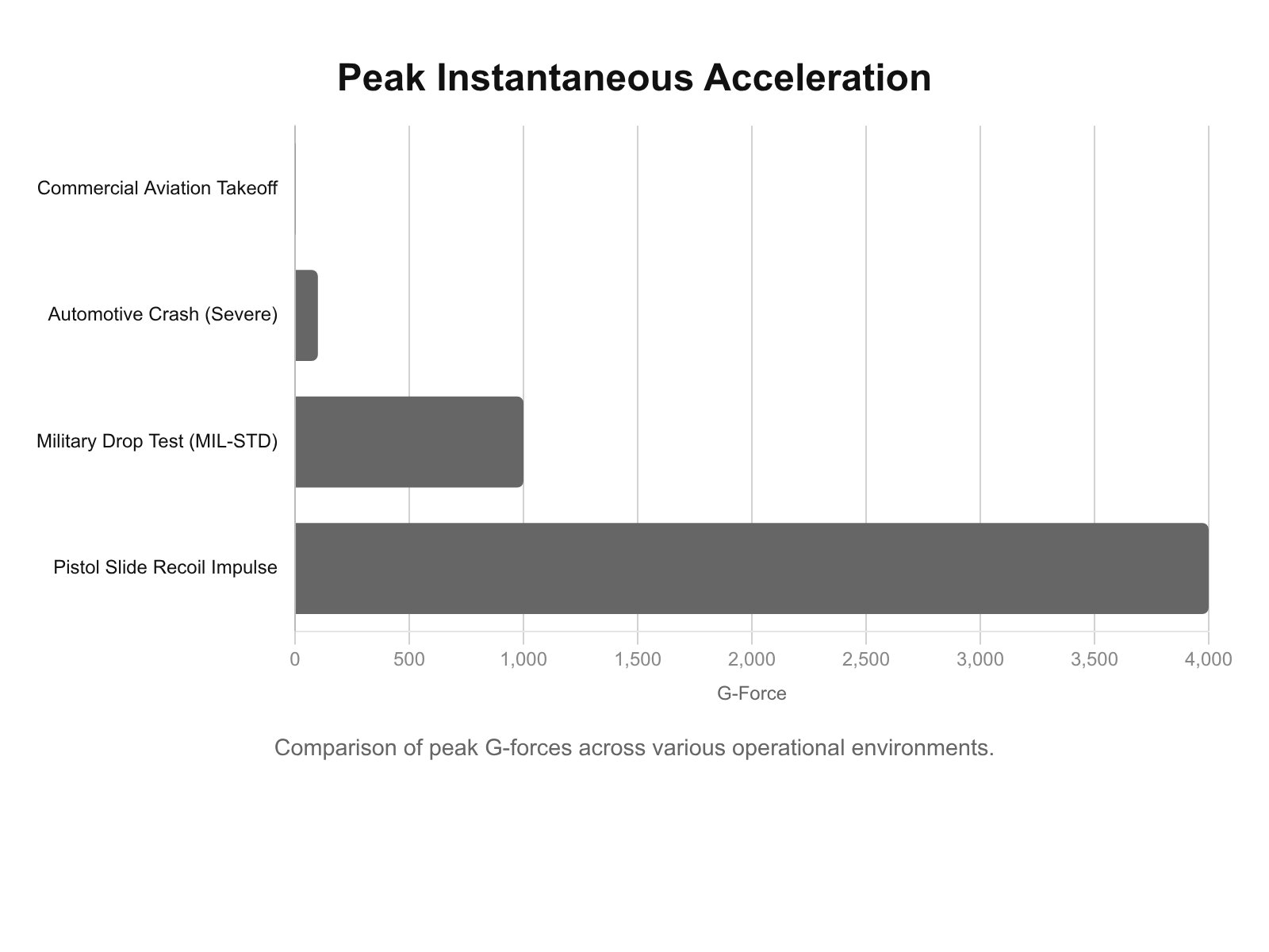
This rapid change in velocity results in peak instantaneous inertial forces during slide impact that approach 2,000 to 4,000 Gs (multiples of Earth’s gravity).12 The US Department of Defense MIL-STD-810H testing protocols for shock (Method 516.8) and vibration (Method 514.8) demonstrate the rigor required for military-grade electronics.14 However, the repetitive gunfire shock profile (Method 519.8) represents a uniquely severe, high-rate repetitive input that causes materials to respond at forced frequencies imposed from the external excitation environment, leading to increased friction or general interference between parts.15
Below is a chart illustrating comparative peak instantaneous accelerations across various operational environments to contextualize the severity of the pistol slide impulse:
2.2 Shear Force Translation and Impact Energy
Applying classical Newtonian mechanics (Force = Mass * Acceleration), the impact of these G-forces on the optic mounting hardware can be mathematically modeled.12 A standard duty-grade enclosed emitter optic, such as the Aimpoint ACRO or Holosun EPS, weighs approximately 50 grams (0.05 kilograms).12
Using the upper limit of slide acceleration (approximately 29,400 meters per second squared, equating to 3,000 Gs), the applied force is calculated as follows: Force = 0.05 kg * 29,400 m/s^2 = 1,470 Newtons.12 Converting Newtons to pounds-force (lbf), 1,470 N is approximately 330 lbf.12
Therefore, with every trigger press, the optic is violently ripped backward as the slide cycles, and then abruptly slammed forward as the slide returns to battery, generating a peak inertial force of 250 to 400 lbf.12 This kinetic energy acts perpendicular to the vertical axis of the mounting screws, creating severe shear stress along the horizontal base of the optic footprint.
2.3 Frequency Analysis and Slide Harmonics
Beyond the macro-level shear forces, the recoil impulse generates complex, high-frequency vibrations within the slide mass. The application of Fast Fourier Transform (FFT) analysis to single-channel acoustic or vibration sources is critical for understanding machinery fault analysis and vibration troubleshooting.18 In the context of a firearm, the barrel and slide assembly act similarly to a cantilevered beam, undergoing longer enduring cycles of numerous frequencies with much lower amplitude following the initial shock impulse.20
When the slide impacts the frame, the resulting shockwave propagates through the steel. These harmonics, often referred to as transverse vibrations, are highly destructive to threaded joints.22 The continuous wavelet transform (CWT) enables the localization of these harmonic shapes in time, revealing that the slide experiences continuous micro-oscillations even as it appears visually stationary.20 If the optic mounting system is not sufficiently rigid or lacks adequate vibration damping, these FFT-analyzed high-frequency waves will initiate the unspooling of fastener threads, a mechanism discussed further in Section 4.3 regarding the Junker Test.
3.0 Mounting Architectures: Direct-Milled versus Adapter Plate Systems
The firearms industry currently supports two primary methodologies for attaching an MRDS to a pistol slide: direct milling and modular adapter plates. The architectural differences between these systems dictate how the previously calculated 330 lbf of shear force is distributed throughout the assembly.1
3.1 Direct-Milled Match-Fit Systems
Direct-milling involves precisely machining a cavity into the top of the pistol slide specifically contoured to the exact dimensions of a single optic footprint.1 The premier iteration of this process is “match-fitting,” wherein a machinist measures the specific optic unit with micrometers and cuts the slide pocket to achieve a total clearance of 0.0005 to 0.001 inches.12
When an optic is match-fit into a milled slide, the physics of the mounting joint shift fundamentally in favor of long-term durability.12 Because the clearances are near zero, the optic housing makes direct, rigid contact with the front and rear steel walls of the slide pocket, as well as the integrated recoil bosses.12 When the slide accelerates, the 330 lbf shear force is transferred directly from the steel mass of the slide into the 7075-T6 aluminum body of the optic.12 The steel walls carry the recoil impulse, completely isolating the mounting screws from shear stress.
In this architecture, the screws are only required to provide the pure vertical clamp load necessary to keep the optic seated flat against the pocket floor.12 This structural approach represents the gold standard for duty-pistol durability, effectively eliminating fastener shear as a primary failure mode.10 The addition of recoil lugs further distributes stress across a broader surface area, preventing screws from loosening or shearing off over time and ensuring consistent zero retention.10
3.2 Adapter Plate Architectures and the Modular Optic System (MOS)
Conversely, the demand for user-level modularity has driven major manufacturers to adopt universal adapter plate systems, most notably the Glock Modular Optic System (MOS).1 In an optics-ready plate configuration, the slide features a generic, oversized cavity designed to accept intermediate adapter plates. The user selects a specific plate corresponding to their desired optic footprint, secures the plate into the slide, and subsequently mounts the optic onto the plate.1
This architecture fundamentally compromises the structural integrity of the mounting system.13 First, it severs the direct steel-to-optic load path. The recoil forces must now travel through a convoluted energy transfer matrix: from the slide, through the plate-mounting screws, into the adapter plate, through the optic-mounting screws, and finally into the optic housing.12 Second, because plates must be mass-produced to accommodate varying manufacturer tolerances across different optic brands, they employ generic cuts with loose clearances. Without the tight support of a match-fit pocket, the initial recoil shear impulse violently impacts the minor diameter of the mounting screws.12
3.3 Tolerance Stacking and Dimensional Variances
The reliance on mass-produced plates introduces the engineering phenomenon of tolerance stacking.30 Every manufactured component possesses an acceptable dimensional variance, or tolerance limit, defined by the machinist. In a direct-milled slide, the stack consists of only two interacting components: the slide pocket and the optic housing. In an adapter plate system, the stack is vastly expanded.32
A standard tolerance stack analysis for a plate system includes:
- The dimensional tolerance of the slide cavity length and width.
- The dimensional tolerance of the adapter plate base.
- The positional accuracy of the slide tapped holes.
- The flatness tolerance of the plate base.
- The flatness tolerance of the plate top surface.
- The dimensional tolerance of the optic housing base.
- The clearance of the plate mounting screws.
- The clearance of the optic mounting screws.
If the slide pocket is machined to the maximum acceptable tolerance (+0.1mm), and the adapter plate is machined to the minimum acceptable tolerance (-0.1mm), cumulative gaps appear.32 The plate is permitted to shift longitudinally under recoil. Furthermore, flatness tolerances are rarely perfect; if a stamped or cast plate is slightly warped, torquing the optic down induces severe bending stress in both the optic housing and the screws, pre-loading the system for fatigue failure before the weapon is even fired.29 This lack of absolute rigidity guarantees that the system’s friction margin will be breached, forcing the fasteners to bear the brunt of the kinetic energy during every shot.
4.0 Fastener Engineering, Torque, and Fatigue Analysis
The longevity of a slide-mounted optic relies entirely upon the mechanical integrity of the threaded fasteners securing it. Analyzing the mechanics of these fasteners under high-stress dynamic conditions reveals why certain mounting methodologies fail consistently while others survive.
4.1 The Torque-Tension Relationship and Clamping Force
In any bolted joint, the primary mechanism preventing lateral movement is not the physical shear strength of the screw shank, but rather the friction generated between the clamped surfaces. This friction is a direct product of the screw’s clamping force (preload) and the coefficient of friction of the mating materials.11 For typical optic mounting screws (e.g., 6-32 or M4 sizes) tightened to the manufacturer-specified torque of 10 to 20 inch-pounds (in-lbs), the resulting clamp load is highly dependent on the friction in the threads.10
To model the required torque and resulting clamping force accurately, mechanical engineering utilizes specific equations that account for friction and the helical angle of the screw. A simplified, widely accepted expression is the standard torque equation:
T = K * F * D
Where:
- T is the applied torque.
- K is the torque coefficient (an estimation including friction and thread helix angle, typically 0.2 for dry steel).
- F is the resulting clamp force.
- D is the nominal bolt shank diameter.11
For a 6-32 screw (nominal diameter 0.138 inches) torqued to 15 in-lbs, the realistic clamp load is approximately 543 lbf per screw, equating to roughly 1,086 lbf for a two-screw system.12
The actual frictional resistance preventing the optic from sliding is calculated by multiplying the total clamp load by the static friction coefficient (mu) of the steel-to-aluminum interface (typically ranging from 0.1 to 0.3, depending on surface finish and lubrication). Thus, the actual friction resistance holding the optic in place ranges from 108 lbf to 325 lbf.12
Because the recoil shear force (calculated previously at 330 lbf) frequently exceeds the friction margin (108-325 lbf), the optic will inevitably micro-slip under recoil unless physically constrained by structural boundaries like recoil lugs or a match-fit pocket.12
4.2 Tensile Strength versus Shear Loading Fatigue
Threaded fasteners are engineered to act as high-tension springs, providing axial clamping force. They are exceptionally poor at resisting repeated, cyclic shear shock.12 Optic mounting screws are typically manufactured from alloy steel, possessing a tensile strength of 120-150 ksi and a shear strength of roughly 70-90 ksi.12 However, these theoretical yield strengths are based on static loads. Under dynamic, repetitive shock loading, the fatigue life of the screw becomes the critical variable.
| Fastener Specification | Typical Metric | Engineering Implications |
| Material Grade | Alloy Steel (Grade 8 equivalent) | High tensile strength; brittle under extreme cyclic shear |
| Common Sizes | 6-32, M3, M4 | Small minor diameter leaves little material at thread root |
| Static Shear Strength | ~70,000 – 90,000 psi | Sufficient for static hold; insufficient for 4,000 G impacts |
| Optimal Engagement | 1.5x Screw Diameter | Requires deep tapped holes; difficult on thin adapter plates |
| Failure Mode | Transverse fatigue cracking | Snaps at the thread root flush with the slide/plate |
| Data Sources | 12 | 12 |
In a loose-fitting plate system, the screws are forced to act as the primary recoil lugs. The optic slides backward across the plate until the screw shank slams against the inner wall of the optic’s mounting hole. Over thousands of rounds, this repetitive shear shock begins to peen the screw holes and elongate the threads.12 Concurrently, the minor diameter of the screw—the weakest point at the root of the threads—develops micro-fractures due to fatigue cumulative damage, consistent with the Miner rule of fatigue.36 Eventually, the screw experiences catastrophic shear failure, snapping flush with the mounting plate and launching the optic from the weapon.9
4.3 The Junker Effect and Transverse Vibration Loosening
Even if the screws do not suffer immediate shear failure, adapter plate systems are highly susceptible to vibration-induced self-loosening. In 1969, German engineer Gerhard Junker revolutionized the understanding of threaded fastener failure through the development of the Junker Test (now standardized as DIN 65151).22 Junker demonstrated that while dynamic axial loads have a negligible effect on bolt loosening, transverse dynamic loads (side-to-side or longitudinal sliding) cause rapid, predictable self-loosening.22
When the 330 lbf recoil force overcomes the 108-325 lbf friction margin in a loose optic pocket, the optic micro-slips relative to the plate.12 During this microscopic transverse movement, the thread flanks and bearing surfaces are momentarily freed from friction. The internal off-torque, stored in the stretched screw as preload, forces the screw to rotate infinitesimally counter-clockwise.22 This process repeats with every trigger press.
As demonstrated by the Junker effect, a loose-fitting plate system will typically experience an initial preload loss of 10-30% in the first few hundred cycles.12 As preload drops, the clamping force drops concurrently, the friction margin vanishes entirely, the slip amplitude increases, and the rate of loosening accelerates exponentially until the screws back out completely.10 This highlights why friction alone is inadequate for securing electronics to reciprocating slide masses.
4.4 Material Yield and Thread Engagement Parameters
To maximize the fatigue life of the mounting system and prevent stripping, the engineering design must allow for proper thread engagement. Industry best practice dictates that high-strength steel screws threading into a steel substrate should have an engagement depth equal to approximately 1.5 times the screw diameter.12 For a 6-32 screw (diameter 0.138 inches), the optimal engagement depth is 0.207 inches.
Adapter plates, by necessity of keeping the optic bore axis as low as possible for co-witnessing with iron sights, are exceptionally thin. Many original equipment manufacturer (OEM) plates provide a mere 0.05 to 0.10 inches of thread engagement.29 This minimal engagement means that torqueing the screw to the required 15 in-lbs risks yielding and stripping the female threads within the plate, permanently destroying the mounting interface. Furthermore, if screws are imperceptibly too long (exceeding 0.045 inches or 3 threads of protrusion), they will bottom out in the slide cavity or interfere with critical internal components, such as the extractor plunger or firing pin safety block, causing weapon malfunctions.34
5.0 Thread-Locker Chemistry, Degradation, and Environmental Survivability
Given the extreme vulnerability of optic screws to transverse vibration and the Junker loosening effect, the application of chemical thread-locking compounds is a non-negotiable requirement for duty weapons.45 However, the specific chemistry of the thread-locker, combined with the thermal and chemical realities of a law enforcement firearm, dictates the ultimate longevity of the mount. The two primary categories of thread-lockers utilized in the firearms industry are anaerobic adhesives and amorphous acrylic polymers.45
5.1 Anaerobic Adhesives (Loctite 242/243) Mechanisms
Loctite 242 and its oil-tolerant successor, Loctite 243 (blue), are anaerobic thermoset plastics. They remain liquid when exposed to oxygen but cure into a hard, crystalline structure in the absence of air and the presence of active metal ions (such as those found in steel fasteners).45 This chemical reaction creates a highly rigid bond that locks the thread flanks together, effectively increasing the breakaway torque required to loosen the screw.48 According to technical data sheets, Loctite 243 yields a breakaway torque of approximately 230 in-lbs (26.0 N·m) on standard M10 steel nuts and bolts.48
While exceptional at preventing static backing out, the rigid thermoset nature of cured Loctite means it can be susceptible to shattering under the high-frequency FFT vibrations and shear shock of a loose optic pocket. Once the crystalline bond is fractured by recoil impulse, its effectiveness is severely diminished.12 Furthermore, it requires a 10-minute fixture time and up to 24 hours for a full cure, and the fastener must be completely cleaned and re-applied if removed.48
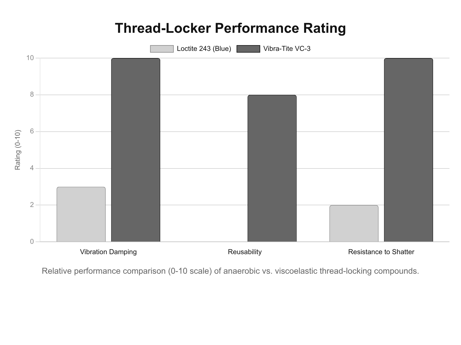
5.2 Amorphous Acrylic Polymers (Vibra-Tite VC-3) Mechanisms
Vibra-Tite VC-3 operates on entirely different chemical principles. It is a blend of cold-flow acrylic polymers suspended in a methyl ethyl ketone (MEK) solvent base.40 Rather than curing into a hard plastic anaerobically, VC-3 is painted onto the screw threads and allowed to air-dry for 10 to 30 minutes before installation.40 The MEK solvent evaporates, leaving a highly viscous, tacky resin.
When torque is applied, the VC-3 cold-flows into the thread gaps. Unlike Loctite, VC-3 remains flexible and resilient.45 This viscoelastic property allows it to act as a micro-shock absorber, dampening the high-frequency vibrations generated during recoil.18 Because it does not shatter under shear shock, VC-3 acts as a continuous friction stabilizer. Additionally, its viscous nature minimizes galling of soft threads and allows screws to be adjusted, removed, and reused up to five times without requiring reapplication, making it highly favored for maintenance-intensive duty guns where optics may need occasional removal for battery swaps.40
5.3 Thermal Degradation and Heat Aging
The slide of a duty pistol can reach extreme temperatures during sustained fire schedules, particularly during qualification courses or prolonged dynamic engagements. Both thread-locker chemistries possess defined thermal ceilings that, when exceeded, lead to compound degradation.
Loctite 243 maintains its strength up to approximately 300°F to 360°F (150°C to 180°C).48 However, technical data indicates a defined degradation curve: testing demonstrates that at 150°C, Loctite 243 retains only 50% of its initial room-temperature strength.50 Vibra-Tite VC-3 features a slightly lower operational temperature ceiling of 165°F (74°C), though its inherent cold-flow properties prevent complete structural failure even when softened by heat.40 If an optic plate is mounted directly over the chamber of the barrel—the hottest point on the firearm—thermal transfer through the slide can soften the thread-locker, exponentially accelerating the Junker loosening effect described in Section 4.3.54
5.4 Chemical Resistance against CLP and Bore Solvents
Law enforcement armorers subject duty firearms to aggressive cleaning regimens, utilizing penetrating oils, carbon solvents (e.g., Hoppe’s No. 9), and ultrasonic tanks. The chemical resistance of the thread-locker is critical to maintaining joint integrity.53
Cured Loctite 243 is highly cross-linked and exhibits excellent resistance to motor oil, unleaded gasoline, and brake fluid.49 Testing shows it retains 100% of its initial strength after 1000 hours of exposure to unleaded gasoline at 23°C.49 However, prolonged exposure to aggressive chlorinated solvents or strong acetone blends can compromise the bond (dropping to 80% strength after 5000 hours in Acetone).48 Vibra-Tite VC-3 acts as a partial corrosion barrier but is highly soluble in methyl ethyl ketone and can be dissolved by specific harsh degreasers.40
For armorers, the critical failure mode occurs when liquid CLP (Cleaner, Lubricant, Preservative) seeps under the optic plate via capillary action. If the screw was under-torqued, or if the thread-locker was improperly applied to oily threads without a primer, the oil penetrates the thread pitch. The oil acts as a lubricant, reducing friction, altering the K-factor of the torque equation, and guaranteeing eventual fastener walk-out.10
| Solvent / Chemical | Loctite 243 Resistance | Vibra-Tite VC-3 Resistance | Operational Risk |
| Motor Oil / CLP | Excellent (115% retention) | Moderate | Capillary seepage reduces friction if untorqued. |
| Unleaded Gasoline | Excellent (100% retention) | Moderate | Low risk in standard LE operational environments. |
| Acetone | Good (80% retention) | Poor / Soluble | High risk during armorer deep-cleaning cycles. |
| MEK (Solvent) | Moderate | Soluble (Base solvent) | Will dissolve VC-3; keep away from optic mounts. |
| Data Sources | 48 | 40 | 35 |
6.0 Metallurgy and Material Science of Mounting Components
The metallurgical composition of the mounting components significantly impacts the overall durability of the system. While the firearm slide is universally machined from hardened ordnance steel (e.g., 416 Stainless or 4140 Chromoly), adapter plates are frequently produced from aluminum to reduce weight and machining costs.58 The interaction between these dissimilar metals under stress creates unique failure vectors.
6.1 7075-T6 Billet Aluminum Properties
The standard in aerospace-grade aluminum is 7075-T6. Alloyed primarily with zinc, magnesium, and copper, 7075-T6 boasts an impressive strength-to-weight ratio, yielding a tensile strength of approximately 83,000 psi (572 MPa).60 It is highly machinable, allowing for intricate designs, and naturally corrosion-resistant when properly anodized.60 However, it is fundamentally softer and more prone to fatigue than steel.62
When analyzing an adapter plate, the primary concern is the integrity of the female threads tapped into the plate. The threads in an aluminum plate are significantly softer than the steel optic screws.58 During installation, if the torque wrench is miscalibrated, or if an armorer inadvertently exceeds the 15 in-lbs specification, the hardened steel screw will effortlessly shear the internal aluminum threads, stripping the plate and rendering the mounting platform useless.34
6.2 4140 Hardened Steel Properties
By comparison, 4140 steel—a low-alloy steel containing chromium, molybdenum, and manganese—when precision CNC machined and heat-treated to a hardness of 40-50 HRC, presents extreme impact resistance, high fatigue strength, and superior thread retention.61
A hardened steel plate survives thousands of rounds of high-caliber recoil without warping or cracking.63 More importantly, the female threads in a 4140 steel plate remain crisp and intact even after hundreds of optic swaps and screw re-torquing cycles.63 While standard, non-hardened steel (20-30 HRC) is prone to denting and galling, proper heat treatment creates a service life that often outlasts the firearm itself. For duty weapons utilizing adapter plates, standardizing on aftermarket heat-treated steel plates (such as those from reputable defense contractors) rather than OEM cast or aluminum plates is an operational imperative to mitigate thread failure.29
6.3 Differential Coefficient of Thermal Expansion (CTE) and Preload Loss
A less obvious but highly destructive failure mode stems from the differential rates of thermal expansion among dissimilar metals. The coefficient of thermal expansion (CTE) defines how much a material expands per degree of temperature increase. Aluminum expands at a rate of approximately 13.0 µin/in-°F, while 4140 steel expands at roughly 6.3 µin/in-°F. Aluminum therefore expands two to three times faster than steel when subjected to heat.58
Consider an optic system comprising a steel slide, an aluminum adapter plate, an aluminum optic housing, and steel mounting screws. As the handgun undergoes a rapid 50-round string of fire during qualification, the barrel and slide heat rapidly, transferring thermal energy into the mounting hardware.66 The aluminum plate and optic housing expand vertically at double the rate of the steel screws holding them down. This differential expansion drastically spikes the tensile stress on the steel screw.58
As the weapon subsequently cools, the aluminum contracts. Over hundreds of these thermal cycles, this thermodynamic pumping action can permanently stretch the screws beyond their elastic limit (plastic deformation), causing a permanent loss of clamp load.12 Once the preload is lost, the friction margin drops to zero, the Junker effect initiates via transverse vibration, and the system fails. Utilizing steel adapter plates matches the CTE of the slide and screws, negating this thermodynamic stress cycle.66
6.4 Galvanic Corrosion and Surface Wear
When two dissimilar metals (e.g., an aluminum optic body and a carbon steel slide) are in direct contact in the presence of an electrolyte (such as ambient moisture, sweat, or rain), galvanic corrosion occurs. The less noble metal (aluminum) acts as an anode and undergoes accelerated corrosion.60 Reputable optic and plate manufacturers combat this through Type III hardcoat anodizing on aluminum components and Nitride, DLC, or Cerakote finishes on steel slides.12
However, the micro-vibration inherent in non-match-fit plate systems eventually wears through these protective coatings at the bearing surfaces—a process known as fretting corrosion.58 Once bare aluminum and steel interact, the localized oxidation creates uneven mating surfaces, which act as pivot points that further compromise the zero of the optic.58 Applying a high-quality thread-locker or dielectric grease beneath the plate can inhibit moisture ingress, but structural rigidity to prevent fretting wear remains the primary defense.35
7.0 Evaluation of Specific Industry Footprints and Next-Generation Interfaces
The landscape of pistol optics is fragmented by competing proprietary footprints, dictating the spacing of screw holes and the geometry of recoil lugs.2 Understanding these interfaces is essential for intelligent procurement.
7.1 Legacy Footprints and Plate Dependencies
The Trijicon RMR footprint remains the dominant standard for full-size duty optics, utilizing 6-32 x 3/8″ screws.44 While robust when direct-milled, adapting the RMR to other platforms requires plates that inherently introduce the tolerance stacking issues detailed in Section 3.3. Similarly, the Leupold DeltaPoint Pro (DPP) utilizes a larger footprint and 6-32 x 1/2″ screws, which, on specific platforms like Glock, require the right-side screw to be filed down to prevent catastrophic interference with the extractor plunger assembly.42 Compact optics, such as the Holosun 407K/507K, utilize a modified RMSc footprint with shorter 6-32 x 7/16″ screws, requiring specialized adapter plates for firearms like the Glock 43X MOS, further complicating armorer supply chains.41
7.2 Proprietary OEM Plate Systems
To accommodate this fragmented market, manufacturers rely on systems like the Glock MOS. The MOS system utilizes a series of numbered adapter plates (e.g., Plate 02 for Trijicon).27 While offering modularity, the MOS plates are notoriously thin, providing minimal thread engagement, and have been widely criticized for their generic tolerances leading to gap-induced shear stress and bent plates.28 By contrast, platforms like the Walther PDP 2.0 and Heckler & Koch VP9 have updated their optic-ready cuts to specific standards that allow certain optics (like the Holosun SCS) to mount directly without plates, restoring the critical steel-to-optic load path and eliminating the plate as a failure point.26
7.3 Enclosed Dovetail Wedges: The Aimpoint A-CUT and COA Paradigm Shift
Recognizing the insurmountable physics of screw shear and tolerance stacking in traditional plate systems, the firearms industry is currently undergoing a paradigm shift in optic mounting methodology.75 In 2025, a collaborative engineering effort produced the Aimpoint COA (Clever Optics Advancement) and its proprietary A-CUT mounting interface.75
The A-CUT interface abandons the flat-bottomed, top-down screw paradigm entirely. Instead, it utilizes a transverse dovetail wedge design integrated directly into the factory slide.71 The optic is stabilized in all directions by a raised shelf that interlocks with a central channel beneath the optic. A steel rear sight plate utilizes two fasteners to secure a secondary wedge that clamps the optic longitudinally.75
The genius of the A-CUT dovetail system lies in force vectoring. When the 330 lbf recoil impulse acts upon the optic, the sheer force is directed entirely into the angled steel walls of the dovetail cut on the slide, not into the fasteners.75 The screws holding the rear wedge plate experience only vertical tensile force perpendicular to the recoil axis, reducing the ’tilt’ between male and female threads that causes fatigue cracking.76 By locking the optic mechanically within the slide mass, the system becomes practically immune to the Junker self-loosening effect.75 Furthermore, the Aimpoint COA optic housing is fully enclosed and purged, offering extreme environmental protection, a 50,000-hour battery life on a single CR2032, and tactile intensity buttons for duty use.75 As exclusive licensing expires, the A-CUT interface represents the eventual obsolescence of the adapter plate system for duty firearms.71
8.0 Strategic Procurement Guidelines for Law Enforcement
8.1 Lifecycle Cost and Maintenance Cycles
The implementation of MRDS technology incurs hidden lifecycle costs that must be factored into agency procurement budgets. Adapter plate systems, while initially appearing cost-effective due to broad compatibility, incur significant downstream financial and operational costs in the form of sheared screws, stripped aluminum plates, and lost or damaged optics.28
Law enforcement armorers must implement strict preventative maintenance (PM) schedules to combat fatigue failure. Optic mounting screws must be classified as consumable items.12 Due to cumulative metal fatigue from continuous shear shock, screws should be replaced every 5,000 rounds, or whenever an optic is uninstalled for maintenance.12 Reusing stretched screws is a primary cause of mount failure. Upon installation, the use of precision torque wrenches calibrated to inch-pounds must be mandated; “hand-tightening” results in wild variations in clamp load and guarantees failure.10 Finally, all optic screws must be marked with bright paint pens (witness marks) to provide operators with a visual indicator of vibration-induced backing out, allowing for intervention before failure becomes catastrophic.12
8.2 RFP Specifications for Duty Handguns
Based on the mechanical evaluation of failure modes, law enforcement agencies drafting Requests for Proposal (RFPs) for duty handguns should enforce stringent mounting interface specifications.72
- Direct-Milled Preference: Agencies should mandate that duty weapons feature factory direct-milled slides matched to a specifically chosen enclosed-emitter footprint. Generic “optics-ready” systems utilizing universal multi-plate adapters should be heavily scrutinized and avoided if dedicated footprint options are available.4
- Adapter Plate Materiality: If legacy weapon systems necessitate the use of adapter plates, procurement documentation must specify that all plates be precision-machined from hardened, heat-treated steel (e.g., 4140 or 17-4 PH stainless).63 Aluminum plates (6061 or 7075) must be explicitly disqualified for duty use due to severe thread failure and thermal expansion risks.34
- Fastener Specifications: Agencies must require high-strength Torx or Torx-Plus screws (T10 or T15) of the exact correct length to maximize thread engagement (1.5x diameter) without protruding into the slide and interfering with internal safety mechanisms.42
- Thread-Locking Protocol: Armorers should standardize on either Loctite 243 for permanent installations, or Vibra-Tite VC-3 for setups requiring modularity and high-vibration damping.45 Strict surface degreasing protocols must precede any application to ensure chemical bonding.46
- Next-Generation Adoption: RFPs should actively solicit dovetail-based enclosed systems (e.g., A-CUT/COA) that inherently bypass fastener shear mechanics, representing the highest tier of officer safety and equipment retention currently available on the market.75
Appendix: Methodology & Data Sources
This intelligence synthesis was conducted via a multi-spectrum Open-Source Intelligence (OSINT) methodology, focusing on biomechanical research, metallurgical data, fastener torque-tension physics, and current law enforcement procurement standards. Data concerning recoil impulses and mathematical force equations were sourced from engineering kinematic analyses of 9mm duty handguns, supplemented by MIL-STD-810H technical documentation.12 Tensile and shear strength limitations of mounting hardware were cross-referenced with studies on transverse vibration and the Junker Test for self-loosening mechanisms.22 The comparative analysis between direct-milling tolerances and modular adapter plates (e.g., MOS) synthesized practical armorer data, CNC machining specifications, and failure-rate testimonies.1 Material science parameters contrasting 7075-T6 aluminum and 4140 steel were sourced from established industrial metallurgical databases and stress-fatigue research.58 Information on the chemical and thermal properties of thread-locking agents (Loctite 243 and Vibra-Tite VC-3) was extracted directly from manufacturer technical data sheets (TDS) and material safety data sheets (MSDS).40 Operational context regarding law enforcement adoption of MRDS systems, including hit-ratio improvements and failure tracking, utilized the Sage Dynamics white paper data (Cowan) and the National Law Enforcement Firearms Instructors Association (NLEFIA) 5-year survey.3 Evaluations of next-generation enclosed dovetail systems relied on technical releases detailing the Aimpoint COA and A-CUT architecture.75
Ronin’s Grips Analytics provides custom, agency-specific data on this topic. Contact us to commission a tailored internal audit or procurement forecast for your department.
Please share the link on Facebook, Forums, with colleagues, etc. Your support is much appreciated and if you have any feedback, please email us in**@*********ps.com. If you’d like to request a report or order a reprint, please click here for the corresponding page to open in new tab.
Sources Used
- Direct-Mounted Red Dots vs Optics-Ready Plate Systems | An Official Journal Of The NRA, accessed March 5, 2026, https://www.shootingillustrated.com/content/direct-mounted-red-dots-vs-optics-ready-plate-systems/
- Popular Red Dot Footprints | Primary Arms, accessed March 5, 2026, https://blog.primaryarms.com/guide/popular-red-dot-footprints/
- Police survey finds pistol red dot sights boost accuracy but training lags – Police1, accessed March 5, 2026, https://www.police1.com/firearms-training/police-survey-finds-pistol-red-dot-sights-boost-accuracy-but-training-lags
- Miniaturized Red Dot Systems for Duty Handgun Use – Kentucky Tactical Officers Association, accessed March 5, 2026, http://www.kentuckytacticalofficersassociation.org/uploads/4/0/6/1/40615731/sage_dynamics_pistol_red_dot_white_paper.pdf
- The verdict on pistol red dot sights in law enforcement: Insights from a 5-year survey, accessed March 5, 2026, https://www.police1.com/police-products/tactical/optics/the-verdict-on-pistol-red-dot-sights-in-law-enforcement-insights-from-a-5-year-survey
- Red Dot Sights For Law Enforcement Use – Scholarly Works @ SHSU, accessed March 5, 2026, https://shsu-ir.tdl.org/bitstreams/3e87cb90-f7da-4d59-999f-d3bffd50cc85/download
- Red dot sights on pistols for patrol officers: Policy and training considerations – Police1, accessed March 5, 2026, https://www.police1.com/police-products/firearms/accessories/sights-scopes/articles/red-dot-sights-on-pistols-for-patrol-officers-policy-and-training-considerations-rmQ5woXwx2xlvfdL/
- Dot or not? – American Police Beat Magazine, accessed March 5, 2026, https://apbweb.com/2025/01/dot-or-not/
- Why Optic Mounting Plates Suck – YouTube, accessed March 5, 2026, https://www.youtube.com/watch?v=LIszWURT8k4
- Avoiding Red Dot Mounting Failures – Uncle Zo, accessed March 5, 2026, https://unclezo.com/2022/11/11/avoiding-red-dot-mounting-failures/
- Calculation of Clamping force from bolt torque – Engineering Stack Exchange, accessed March 5, 2026, https://engineering.stackexchange.com/questions/8324/calculation-of-clamping-force-from-bolt-torque
- A deep nerdy dive into match-fit optics… – Nameless Arms, accessed March 5, 2026, https://www.namelessarms.com/post/a-deep-nerdy-dive-into-match-fit-optics
- The Pros and Cons of a Miniature Red Dot Sight and Slide Cuts on a Defensive Pistol, accessed March 5, 2026, https://www.itstactical.com/warcom/firearms/miniature-red-dot-sight-slide-cuts-defensive-pistol/
- MIL-STD-810 H Environmental Engineering Test Lab – Keystone Compliance, accessed March 5, 2026, https://keystonecompliance.com/mil-std-810-h/
- MIL-STD-810 Test Method 519 Gunfire Shock Testing, accessed March 5, 2026, https://mil810.com/test-methods/gunfire/
- Optical method for accurate force measurement: dynamic response evaluation of an impact hammer – SPIE Digital Library, accessed March 5, 2026, https://www.spiedigitallibrary.org/journals/optical-engineering/volume-45/issue-02/023002/Optical-method-for-accurate-force-measurement–dynamic-response-evaluation/10.1117/1.2170713.full
- MILITARY & LAW ENFORCEMENT – Lawmen Supply Company, accessed March 5, 2026, https://lawmensupplyco.com/wp-content/uploads/2025/05/aimpointcatalog.pdf
- FFT Analysis and Tone Assessment | SoundAdvisor 831C – Larson Davis, accessed March 5, 2026, https://www.larsondavis.com/Products/sound-level-meters/soundadvisor-831C/firmware/FFTAnalysisandToneAssessment
- Vibration Analysis: FFT, PSD, and Spectrogram Basics [Free Download] – enDAQ Blog, accessed March 5, 2026, https://blog.endaq.com/vibration-analysis-fft-psd-and-spectrogram
- Spectral analysis of rifle barrel harmonics – Indico, accessed March 5, 2026, https://indico.fjfi.cvut.cz/event/98/contributions/2109/contribution.pdf
- Harmonics and F-Open stock | Page 2 | Shooters’ Forum, accessed March 5, 2026, https://forum.accurateshooter.com/threads/harmonics-and-f-open-stock.4079995/page-2
- Self-loosening of threaded fasteners | Bolt Science, accessed March 5, 2026, https://www.boltscience.com/pages/self-loosening-of-threaded-fasteners.pdf
- Red Dot Sight Mounting Methods: Comparing Structures, Heights, and Positions – Foreseen, accessed March 5, 2026, https://www.foreseenoptics.com/red-dot-sight-mounting-methods-comparing-structures-heights-and-positions
- The Advantages of Recoil Lugs in Pistol Red Dot Slide Cuts, accessed March 5, 2026, https://stonebridgegunworks.com/The-Advantages-of-Recoil-Lugs-in-Pistol-Red-Dot-Slide-Cuts_b_10.html
- The Precision Advantage: Why Direct Optic Milling for Glocks Trumps the Glock MOS System, accessed March 5, 2026, https://blackphoenixcustoms.com/whydirectopticmillingforglockstrumpstheglockmossystem
- Footprints/Mounting Standards on Red Dot Sights – Optics Trade Blog, accessed March 5, 2026, https://www.optics-trade.eu/blog/footprints-on-red-dot-sights/
- MOS Configuration – GLOCK Perfection, accessed March 5, 2026, https://eu.glock.com/en/Technology/MOS-Configuration
- Should you avoid adapter plate and go direct mount as much as possible? – Reddit, accessed March 5, 2026, https://www.reddit.com/r/CCW/comments/1hlgjxt/should_you_avoid_adapter_plate_and_go_direct/
- MOS mounting plates : r/Glocks – Reddit, accessed March 5, 2026, https://www.reddit.com/r/Glocks/comments/w8j3dj/mos_mounting_plates/
- Statistical Tolerance and Clearance Analysis for Assembly – NASA Technical Reports Server (NTRS), accessed March 5, 2026, https://ntrs.nasa.gov/citations/20060036678
- How do everyone do tolerance stack up analysis at work? : r/AskEngineers – Reddit, accessed March 5, 2026, https://www.reddit.com/r/AskEngineers/comments/usqr00/how_do_everyone_do_tolerance_stack_up_analysis_at/
- Step-by-Step Example of Tolerance Analysis – Jaap Vink, accessed March 5, 2026, https://vinksda.com/step-by-step-example-of-tolerance-analysis/
- The Three Steps of Tolerance Analysis | Simplexity PD, accessed March 5, 2026, https://www.simplexitypd.com/blog/tolerance-analysis/
- MOS plate reliability : r/Glocks – Reddit, accessed March 5, 2026, https://www.reddit.com/r/Glocks/comments/1455xrt/mos_plate_reliability/
- strength of 6-48 compared to 8-40 – Shooters’ Forum, accessed March 5, 2026, https://forum.accurateshooter.com/threads/strength-of-6-48-compared-to-8-40.4071594/
- Research Article Impact Characteristics and Fatigue Life Analysis of Multi-Wire Recoil Spring for Guns, accessed March 5, 2026, https://pdfs.semanticscholar.org/0773/87b853d039893da70f7a579e74b219f47cc8.pdf
- Optimization of anti-loosening bolt based on double thread mechanism – PMC – NIH, accessed March 5, 2026, https://pmc.ncbi.nlm.nih.gov/articles/PMC11015383/
- Junker test – Wikipedia, accessed March 5, 2026, https://en.wikipedia.org/wiki/Junker_test
- Analysis of Vibration loosening of bolted fasteners – Engineering Research Publication, accessed March 5, 2026, https://www.erpublication.org/published_paper/IJETR2206.pdf
- Vibra-Tite VC-3 Threadmate, accessed March 5, 2026, https://www.vibra-tite.com/threadlockers/plastic-compatible/vibra-tite-vc-3-threadmate/
- Choosing the Right Glock 43X MOS Adapter Plate: Elevate Your Optics Ga | AltitudeCraft, accessed March 5, 2026, https://www.altitudecraft.com/blogs/insights/glock-43x-mos-adapter-plate-holosun-507k
- Are these screws too short to hold my optic on? : r/SigSauer – Reddit, accessed March 5, 2026, https://www.reddit.com/r/SigSauer/comments/11n7i6w/are_these_screws_too_short_to_hold_my_optic_on/
- FN Issues Optics Mounting Service Bulletin for FN Reflex MRD Pistols | FN® Firearms, accessed March 5, 2026, https://fnamerica.com/press-releases/fn-issues-optics-mounting-service-bulletin-for-fn-reflex-mrd-pistols/
- Red Dot Mounting Screws: Size and Torque Guide for Glock Slides (Trijicon, Holosun, Leupold) – Legion Precision Weapon Systems, accessed March 5, 2026, https://legion-precisionweaponsystems.com/red-dot-mounting-screws-size-and-torque-guide-for-glock-slides-trijicon-holosun-leupold/
- What Is Threadlocker? Vibra-Tite 121 vs Vibra-Tite VC-3 Explained – Four Brothers Holsters, accessed March 5, 2026, https://fourbrothersinc.com/blogs/four-brothers-holsters-expertise/what-is-threadlocker-vibra-tite-121-vs-vibra-tite-vc-3-explained
- Quick Tip: The When, Where and What of Threadlocker – YouTube, accessed March 5, 2026, https://www.youtube.com/watch?v=vTR0rOFSNHU
- Threadlockers: A Guide for AR-15 DIY’ers – BRD Gun Works, accessed March 5, 2026, https://brdgunworks.com/2021/02/08/threadlockers-a-guide-for-ar-15-diyers/
- LOCTITE® 243 – Henkel Adhesives, accessed March 5, 2026, https://www.henkel-adhesives.com/tn/en/product/threadlockers/loctite_2430.html
- LOCTITE® 243 – RS Online, accessed March 5, 2026, https://docs.rs-online.com/22f6/0900766b80076c5f.pdf
- Technical Data Sheet Product 243 – Farnell, accessed March 5, 2026, https://www.farnell.com/datasheets/24239.pdf
- VIBRA-TITE® VC-3® | ND Industries, accessed March 5, 2026, https://www.ndindustries.com/wp-content/uploads/pds_vibra-tite-vc-3.pdf
- Safety Data Sheet – Vibra-Tite, accessed March 5, 2026, https://www.vibra-tite.com/wp-content/uploads/SDS-VT213-Vibra-TITE__VC-3-USEN.pdf
- Loctite 222/243 or Vibratite? : r/beretta1301 – Reddit, accessed March 5, 2026, https://www.reddit.com/r/beretta1301/comments/1j366i6/loctite_222243_or_vibratite/
- What advantage/disadvantages of Loctite for mounting optics? I’ve never used it in my life., accessed March 5, 2026, https://www.reddit.com/r/Firearms/comments/10rowqh/what_advantagedisadvantages_of_loctite_for/
- Performance Characterization of Loctite 242 and 271 Liquid Locking Compounds (LLCs) as a Secondary Locking Feature for Interna – NASA Technical Reports Server, accessed March 5, 2026, https://ntrs.nasa.gov/api/citations/20110011064/downloads/20110011064.pdf
- Loctite 243 Blue 50 ml Threadlocker – Tameson.com, accessed March 5, 2026, https://tameson.com/products/loctite-243-blue-50-ml-threadlocker
- Why you are probably using loctite completely wrong, and the only reason you have gotten by with it is because you are dumb. (Actual Technical Post) : r/guns – Reddit, accessed March 5, 2026, https://www.reddit.com/r/guns/comments/84x0ay/why_you_are_probably_using_loctite_completely/
- Steel vs. Aluminum Scope Mounts: Which Is Right for You?, accessed March 5, 2026, https://weavermounts.com/articles/steel-vs-aluminum-scope-mounts-which-is-right-for-you/
- Aluminum vs. Steel Mounts | Optics Trade Debates, accessed March 5, 2026, https://www.optics-trade.eu/blog/aluminum-mounts-vs-steel-mounts/
- Aluminum Or Steel Red Dot Mount? – Outer Impact Firearms & Motorsports, accessed March 5, 2026, https://outerimpact.com/aluminum-vs-steel-red-dot-mounts-which-material-is-the-right-one-for-your-red-dot/
- 7075 Billet Aluminum vs 4140 Steel: A Difference Guide | VMT, accessed March 5, 2026, https://vmtcnc.com/7075-billet-aluminum-vs-4140-steel/
- 7075 Billet Aluminum vs 4140 Steel: Material Showdown | PTJ Blog – CNC machining, accessed March 5, 2026, https://www.cncmachiningptj.com/article-1384.html
- Hardened Heat-Treated Steel Outperforms Standard Steel & Aluminum – Athena Precision, accessed March 5, 2026, https://www.athenaprecision.com/blogs/athena-precision-blog/why-athena-precision-s-hardened-heat-treated-steel-red-dot-plates-outperform-standard-steel-and-aluminum
- 7075 Billet Aluminum vs. 4140 Steel: A Detailed Comparison Guide, accessed March 5, 2026, https://www.machining-custom.com/blog/7075-billet-aluminum-vs-4140-steel.html
- Fatigue behavior of notched and unnotched 7075-T6 aluminum alloy subjected to re-aging (RRA) heat treatment and plasma nitriding | Request PDF – ResearchGate, accessed March 5, 2026, https://www.researchgate.net/publication/373120887_Fatigue_behavior_of_notched_and_unnotched_7075-T6_aluminum_alloy_subjected_to_re-aging_RRA_heat_treatment_and_plasma_nitriding
- aluminum vs. steel base? – Nosler Reloading Forum, accessed March 5, 2026, https://forum.nosler.com/threads/aluminum-vs-steel-base.27225/
- Does Loctite alter torque on scope rings | Page 5 | Rokslide Forum, accessed March 5, 2026, https://rokslide.com/forums/threads/does-loctite-alter-torque-on-scope-rings.381464/page-5
- A frank, open, and honest discussion of threadlocking products. | Canadian Gun Nutz, accessed March 5, 2026, https://www.canadiangunnutz.com/forum/threads/a-frank-open-and-honest-discussion-of-threadlocking-products.2291794/
- Securing fasteners from loosening in high vibration environment : r/MechanicalEngineering, accessed March 5, 2026, https://www.reddit.com/r/MechanicalEngineering/comments/1fjqejz/securing_fasteners_from_loosening_in_high/
- Gunsmithing – Thread locker when and when not to use | Sniper’s Hide Forum, accessed March 5, 2026, https://www.snipershide.com/shooting/threads/thread-locker-when-and-when-not-to-use.7066220/
- Mounting Standards: 2026 Guide to Red Dot Footprints – Inside Safariland, accessed March 5, 2026, https://inside.safariland.com/blog/mounting-standards-a-guide-to-red-dot-footprints/
- Implementing Red Dot Sights for Your Agency – Police and Security News, accessed March 5, 2026, https://policeandsecuritynews.com/2023/06/01/implementing-red-dot-sights-for-your-agency/
- Holosun 507K Review: Best Micro Red Dot for CCW Tested 2026 – Scopes Field, accessed March 5, 2026, https://scopesfield.com/holosun-507k-review/
- MOS vs COA : r/Glocks – Reddit, accessed March 5, 2026, https://www.reddit.com/r/Glocks/comments/1j7yye9/mos_vs_coa/
- 2025 Red Dot of the Year – Guns and Ammo, accessed March 5, 2026, https://www.gunsandammo.com/editorial/2025-GA-awards-red-dot/539808
- Aimpoint’s New COA: Clever Optics Advancement – YouTube, accessed March 5, 2026, https://www.youtube.com/watch?v=EkFQNELaQp0
- Aimpoint broadens COA and A-Cut adoption across leading pistol brands – Police1, accessed March 5, 2026, https://www.police1.com/police-products/tactical/optics/aimpoint-broadens-coa-and-a-cut-adoption-across-leading-pistol-brands
- [SHOT 2025] Aimpoint COA Red Dot Sight and A-CUT Footprint | thefirearmblog.com, accessed March 5, 2026, https://www.thefirearmblog.com/blog/shot-2025-aimpoint-coa-red-dot-sight-and-a-cut-footprint-44818390
- Replacement Duty Weapons System – SAM.gov, accessed March 5, 2026, https://sam.gov/workspace/contract/opp/9d8942e30f214155bddb16a8e95e460e/view
- COA – Aimpoint, accessed March 5, 2026, https://aimpoint.us/aimpoint-coa/
- COA | Aimpoint, accessed March 5, 2026, https://www.aimpoint.com/coa-launch/
- How often do you see Holosun *rifle* optics break? : r/ar15 – Reddit, accessed March 5, 2026, https://www.reddit.com/r/ar15/comments/1ddh9fi/how_often_do_you_see_holosun_rifle_optics_break/
- Getting started with pistol red dot sights: Benefits, drawbacks and training tips – Police1, accessed March 5, 2026, https://www.police1.com/police-products/firearms/training/getting-started-with-pistol-red-dot-sights-benefits-drawbacks-and-training-tips
- Baseline Specifications for Law Enforcement Service Pistols with Security Technology – Office of Justice Programs, accessed March 5, 2026, https://www.ojp.gov/pdffiles1/nij/250377.pdf
- Screw Tightening Torque Values in Riflescope Mounting – Optics Trade Blog, accessed March 5, 2026, https://www.optics-trade.eu/blog/screw-tightening-forces-in-riflescope-mounting/
- Torque specs for glock MOS plate. – Reddit, accessed March 5, 2026, https://www.reddit.com/r/Glocks/comments/1odquu6/torque_specs_for_glock_mos_plate/
- CCW Red Dot pushback – Reddit, accessed March 5, 2026, https://www.reddit.com/r/CCW/comments/1jp1pek/ccw_red_dot_pushback/
- California Highway Patrol, accessed March 5, 2026, https://information.auditor.ca.gov/pdfs/sr2009/2007-111.pdf
- MOS vs Milled (READ POST) : r/Glocks – Reddit, accessed March 5, 2026, https://www.reddit.com/r/Glocks/comments/136rznk/mos_vs_milled_read_post/