1. Executive Summary and Macro-Industrial Context
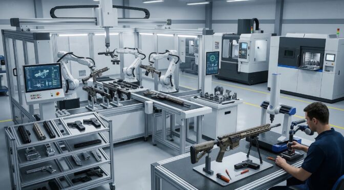
The small arms and tactical accessories manufacturing sector in 2025 and 2026 is undergoing an unprecedented paradigm shift, driven by the aggressive convergence of simultaneous 5-axis Computer Numerical Control (CNC) machining, sub-micron 3D scanning metrology, and advanced parametric reverse engineering workflows.1 Historically, the production of mission-critical defense components was dominated by tier-one defense contractors possessing massive capital expenditure capabilities and sprawling, highly sequential production lines. However, the contemporary landscape is experiencing a profound democratization of high-precision manufacturing.3 Small-to-Medium Enterprises (SMEs), particularly those clustered within advanced manufacturing hubs such as Michigan’s “Automation Alley,” are aggressively leveraging these highly automated, interconnected technologies to secure, execute, and scale critical defense contracts.5
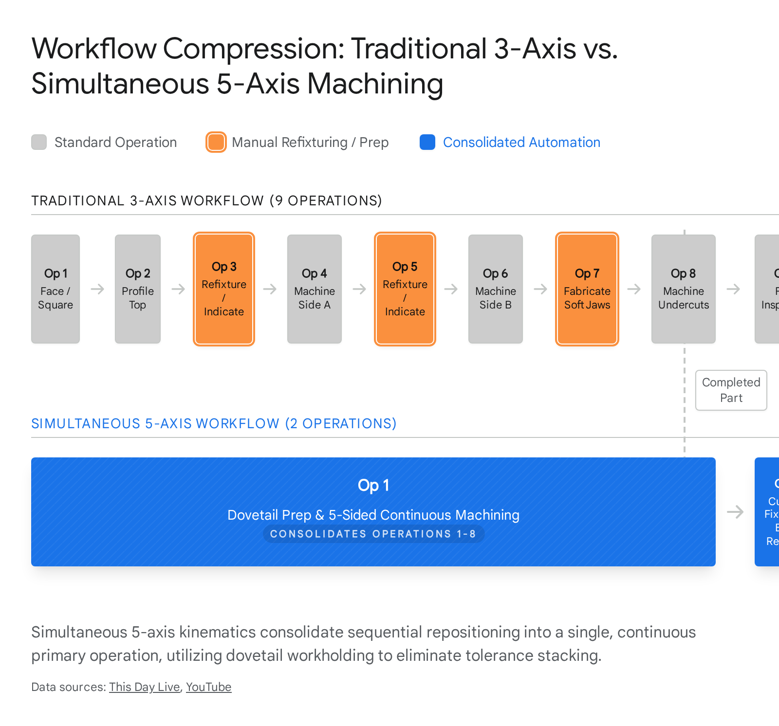
This comprehensive technical analysis examines the transformative impact of these specific advanced manufacturing technologies on the defense supply chain. The integration of continuous 5-axis kinematics has completely redefined baseline operational efficiency within the sector. Most notably, this technology has facilitated the compression of traditional, highly fragmented multi-step manufacturing sequences into consolidated, two-operation workflows.7 This consolidation drastically lowers prototyping costs, accelerates time-to-market, and virtually eliminates the insidious issue of tolerance stacking that plagues sequential machining methodologies.7 Concurrently, the proliferation of high-resolution 3D metrology hardware and AI-assisted parametric reverse engineering software has unlocked previously impossible capabilities in ergonomic customization, component modernization, and the sustainment of legacy military platforms.10
Furthermore, a fundamental and permanent transition in materials science is occurring directly on the factory floor. To meet the stringent demands of modern combat environments, which dictate extreme weight reduction, thermal management, and structural rigidity, the industry is rapidly adopting high-performance, aerospace-grade aluminum alloys, specifically the 7075-T6 specification.13 This transition is occurring alongside the integration of advanced heat-resistant engineered thermoplastics, such as Polyetheretherketone (PEEK) and its highly abrasive glass-filled variants (PEEK-GF30).15 Processing these disparate materials necessitates entirely new, divergent machining philosophies, emphasizing strict heat control, ultra-rigid fixturing, optimized chip evacuation, and specialized Polycrystalline Diamond (PCD) tooling.17 By analyzing the intricate technical metrics, complex toolpath strategies, machine kinematics, and material behaviors associated with these technologies, this report provides an exhaustive, peer-level blueprint of the modern small arms manufacturing ecosystem.
2. Kinematics, Dynamics, and the 5-Axis Machining Revolution
2.1. The Shift from Sequential to Simultaneous Multi-Axis Machining
The foundational technology driving the current revolution in tactical accessory production is the 5-axis CNC machining center. To understand the magnitude of this shift, one must analyze the kinematic limitations of legacy systems. Traditional 3-axis machines dictate that a cutting tool moves exclusively along three linear planes: the X-axis (left-to-right), the Y-axis (front-to-back), and the Z-axis (up-and-down).18 Consequently, the cutting tool remains perpendicular to the workpiece at all times. A 5-axis machining center, however, introduces two additional rotational axes. Depending on the specific machine architecture, such as a trunnion table configuration (table/table) or a swivel-head configuration (head/head), these rotational axes are typically designated as the A-axis (rotating around the X-axis), the B-axis (rotating around the Y-axis), and the C-axis (rotating around the Z-axis).18
It is absolutely critical to distinguish between 3+2 positional machining and full, simultaneous 5-axis contouring. In 3+2 machining, also known as positional 5-axis machining, the rotational axes are utilized solely to orient the workpiece to a fixed, static position.7 Once locked into place, standard 3-axis milling programs execute the material removal. While this significantly reduces the need for manual refixturing by an operator, it is fundamentally incapable of producing the complex, sweeping organic contours required by modern aerodynamic ballistics or ergonomic tactical components.7
Full simultaneous 5-axis machining, conversely, engages all five axes (three linear, two rotational) concurrently and dynamically.9 The orientation of the cutting tool changes continuously relative to the workpiece throughout the execution of the toolpath.20 This capability allows programmers to utilize significantly shorter, more rigid cutting tools because the tool holder can tilt away from deep cavity walls, avoiding collisions.9 The employment of shorter tools dramatically reduces tool deflection and eliminates harmonic vibration (chatter) during high-speed cutting.22 Consequently, manufacturers achieve superior surface finishes that often eliminate the need for secondary hand-polishing operations, while simultaneously holding dimensional tolerances as tight as ±0.0025mm to ±0.005mm under standardized operations.7
In the context of small arms manufacturing, this continuous kinematic freedom translates directly to the production of monolithic components. Parts that previously required the complex welding, brazing, or mechanical fastening of multiple disparate sub-assemblies can now be carved efficiently from a single solid billet of material.7 This “done-in-one” approach fundamentally eliminates the structural vulnerabilities, stress risers, and failure points inherently associated with mechanical joints and welded seams, significantly enhancing the reliability of firearms subjected to extreme ballistic pressures, thermal shock, and environmental degradation.7
2.2. Machine Architecture and Metrological Stability
The execution of these complex simultaneous movements requires extraordinary mechanical rigidity and metrological stability within the machine tool itself. High-end 5-axis centers, such as those manufactured by Hermle or the GROB Systems G550 universal machining center, are engineered to mitigate the specific challenges introduced by multi-axis motion.23
Key architectural considerations include static rigidity, which dictates the machine’s resistance to deflection under heavy cutting forces, and dynamic stability, which ensures accuracy during rapid, multi-axis accelerations and decelerations.25 Furthermore, thermal stability is a critical metric. As spindles spin at excess of 20,000 RPM and linear drives rapidly actuate, the machine structure absorbs heat, leading to microscopic dimensional drift.25 Modern 5-axis machines employ temperature-controlled structures, chilled ball screws, and advanced vibration damping casting materials (such as polymer concrete or epoxy granite) to maintain absolute precision over extended “lights-out” production runs.25 Backlash, the slight mechanical play or slack in a drive system when reversing direction, is virtually eliminated through the use of high-efficiency, pre-loaded ball screws manufactured from high-performance alloy steels.27
| Machining Metric | Traditional 3-Axis Capability | Simultaneous 5-Axis Capability | Operational Impact on Defense Manufacturing |
| Kinematic Motion | Linear X, Y, Z only. Tool remains perpendicular to part. | Concurrent X, Y, Z, A, B/C motion. Tool orientation adapts dynamically. | Enables machining of undercuts, complex organic surfaces, and deep internal cavities without collision. |
| Setup Requirements | Requires up to 9 manual refixturing operations for complex parts. | Minimum 1 to 2 setups utilizing dovetail workholding. | Drastically reduces machine downtime, labor costs, and cumulative tolerance stacking errors. |
| Tooling Rigidity | Often requires long reach tools to access deep features, causing deflection. | Allows tilting of the spindle/table, enabling the use of short, highly rigid tools. | Eliminates vibration and chatter, resulting in superior surface finishes and extended tool life. |
| Part Consolidation | Complex assemblies require multiple parts fastened or welded together. | “Done-in-one” capability allows monolithic part creation from solid billets. | Enhances structural integrity by eliminating weak mechanical joints and failure points. |
| Achievable Tolerances | Subject to error accumulation across multiple setups. | High precision maintained across a single setup (±0.0025mm achievable). | Ensures strict compliance with aerospace and defense First Article Inspection (FAI) standards. |
3. The 9-to-2 Workflow Paradigm and Supply Chain Economics
3.1. Dismantling the Sequential Bottleneck
The most quantifiable metric of operational efficiency in modern 5-axis machining is the radical reduction in setup operations. To appreciate this advancement, one must analyze the severe limitations of traditional 3-axis manufacturing workflows. Producing complex firearm components, such as highly contoured custom receivers or ergonomic anatomical hand grips, historically necessitated up to nine distinct operational steps.8
A traditional workflow dictated facing the raw stock, machining the top profile, and then manually removing the part from the machine. The operator would then have to manually deburr the component, flip it, and re-indicate it into multiple specialized fixtures or custom-machined soft jaws to sequentially access the remaining sides.18 Every single manual intervention and refixturing event forced the machine spindle to stop, resulting in zero value-added production.28 More critically, every setup introduced the risk of human error and the phenomenon of “tolerance stacking.” Tolerance stacking occurs when the minuscule, acceptable dimensional deviations in one setup accumulate and compound in subsequent setups, ultimately pushing the final machined features out of geometric specification, resulting in costly scrap and rework.7
Advanced 5-axis technology has aggressively compressed this convoluted, labor-intensive process into a highly streamlined two-operation workflow, colloquially known within the industrial engineering community as the 9-to-2 paradigm.8 This methodology is perfectly illustrated in the manufacturing of highly complex, contoured hand grips utilizing advanced multi-axis machinery such as the DN Solutions DVF 5000.8
3.2. Execution of the 2-Operation Workflow
The modern 5-axis workflow relies entirely on specialized workholding strategies that maximize workpiece exposure while maintaining extreme rigidity.
Operation 1 (Op 1): Material Preparation and Primary Machining The process begins with critical material preparation. The raw aluminum or high-performance polymer billet is machined to feature a precision dovetail cut at its base.8 This dovetail acts as the primary, and often sole, workholding interface. It is designed to integrate seamlessly with specialized, high-clamping-force 5-axis self-centering vises. The mechanical advantage of the dovetail provides an exceptionally rigid grip on a remarkably minimal surface area, exposing five full sides of the workpiece simultaneously to the cutting spindle.
During programming, CAM engineers mathematically allocate an extra inch of sacrificial stock material at the base to physically lift the primary part geometry away from the vise jaws.8 This extra stock provides the necessary physical clearance for high-speed toolholders and the machine spindle to articulate around the part at extreme angles without risking catastrophic collisions.8 In this single, continuous, highly automated setup, the 5-axis machine roughs and finishes the entire external ergonomic profile, internal cavities, undercuts, and mounting interfaces. The part is completed to its final dimensions on five of its six sides without a single manual intervention.
Operation 2 (Op 2): Conformal Fixturing and Finalization The second operation is strictly required to remove the sacrificial dovetail base and finish the sixth and final side of the component.8 Because the part now features complex, organic exterior contours generated during Op 1, standard flat vise jaws cannot secure it without causing severe surface marring, point-loading, or structural crushing.
Therefore, Op 2 utilizes a custom-machined or 3D-printed conformal fixture that perfectly matches the negative geometric topology of the machined grip.8 This specialized fixture cradles the part securely, distributing clamping forces evenly and protecting the pristine surface finish. This surface protection is especially critical for defense components destined for specialized post-processing, such as Top 3 Hard Ionize Coating or Type III hardcoat anodizing, where surface blemishes are unacceptable.8 Locked in this conformal fixture, the machine rapidly faces off the dovetail base, finalizes any remaining geometry, and ejects a completed, monolithic part.8
3.3. Cost Compression and Supply Chain Economics
While the initial capital expenditure for a simultaneous 5-axis CNC machining center, high-end tooling, and its accompanying computer-aided manufacturing (CAM) software is undeniably substantial, the Total Cost of Ownership (TCO) rapidly undercuts traditional methodologies. Comprehensive industry data from early 2026 indicates that the implementation of 5-axis technology reduces the total cost of producing customized, highly complex parts by approximately 30%.7
This significant cost compression is not achieved through faster raw cutting speeds, but rather is derived from multiple compounding operational efficiencies. First, the total elimination of intermediate setups inherently maximizes overall machine spindle utilization (uptime).7 Manufacturers are no longer paying highly skilled, expensive machinists to spend hours dialing in dial indicators, squaring blocks, and aligning parts; instead, operators are strictly focused on loading raw stock, engaging automatic tool changers (ATC), and monitoring continuous, automated cycles.7
Second, the dramatic reduction in specialized fixture fabrication significantly lowers both material and indirect labor costs.18 Third, and perhaps most economically impactful, completing complex features in a single clamping avoids the cumulative geometric errors that cause parts to fall out of tolerance, thereby slashing scrap rates and drastically improving first-pass yields.7 Ultimately, these combined efficiencies generate a significantly faster Return on Investment (ROI) and grant agile SMEs the ability to quote lower prices with shorter lead times than legacy competitors relying on sequential processing.
4. Unlocking Complex Geometries and Advanced Weaponry Features
The kinematic freedom provided by 5-axis machining, when combined with the data density of high-fidelity digital metrology, has unlocked entirely new design paradigms in small arms manufacturing. Components are no longer constrained by the physical limitations of orthogonal cutting tool approaches. Engineers are now free to design for maximum ballistic, aerodynamic, and ergonomic performance, rather than designing for manufacturability on a 3-axis mill.
4.1. Ergonomic Customization through Sub-Micron Reverse Engineering
The modern tactical accessories market places an absolute premium on hyper-ergonomic interfaces. Historically, standardized, uniformly sized pistol grips, rifle chassis, and foregrips forced operators to adopt biomechanically inefficient gripping methods.29 This lack of anthropometric consideration led to rapid muscle fatigue, reduced fine motor dexterity, and diminished recoil control, particularly for end-users with smaller hands, combat injuries, or physiological limitations such as arthritis.29 To comprehensively address this, manufacturers are leveraging 3D scanning and reverse engineering to create highly customized, user-specific, organic geometries that map perfectly to individual hand contours.
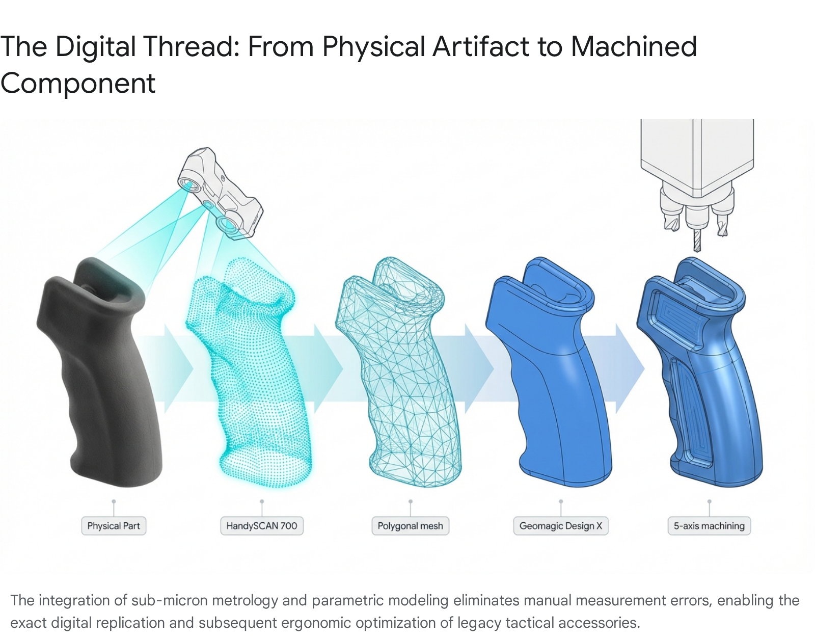
The technical workflow for this extreme customization relies heavily on industrial-grade, non-contact metrology. Traditional methods of reverse engineering legacy firearm components relied on manual measurements using digital calipers, micrometers, or optical comparators, supplemented by photogrammetry with reference scales.11 These archaic methods were notoriously prone to human error, severe error stacking, and required extensive “fitment trial and error” that delayed product development and extended time-to-market.11
In 2026, manufacturers exclusively utilize advanced laser and structured light scanners, such as the Creaform HandySCAN 700 or the HandySCAN Black Elite Plus.8 These devices boast astonishing volumetric accuracies of up to 0.03mm (0.0012 inches).11 These scanners capture millions of discrete data points per second, projecting a laser grid over the object to create a flawless, high-resolution polygonal point cloud mesh of an existing firearm frame, or a custom hand-molded anatomical clay prototype.10
4.2. The Parametric Conversion Pipeline
The preparation for scanning is minimal but absolutely critical to downstream success. If a legacy part features aggressive surface stippling, checkering, or manufacturing defects that are not desired in the final CAD model, engineers will carefully fill and smooth these textures using industrial modeling clay or coat the part in a temporary, washable matte powder.11 This crucial step prevents the scanning software from rendering an overly complex, “noisy” mesh that would computationally bog down the reverse engineering software.11
The captured 3D polygonal mesh is then imported into advanced, specialized reverse engineering software platforms, such as Geomagic Design X or the XTract3D plug-in utilized within the Dassault Systèmes SolidWorks environment.11 Within the software architecture, engineers utilize automated surface-fitting algorithms to convert the static, “dumb,” and non-editable polygonal mesh into a fully parametric CAD model composed of Non-Uniform Rational B-Splines (NURBS) surfaces.10
This conversion is the linchpin of the entire process. Once the geometry exists in a parametric state with a fully populated feature tree, the digital twin can be infinitely and precisely manipulated.10 Design engineers can finely tune grip angles to match optimal wrist biomechanics, optimize overall weapon weight distribution by hollowing internal cavities, and adjust trigger reach geometries. Crucially, while the external ergonomic envelope is modified, the parametric software ensures that the original mechanical mating surfaces, such as the exact dimensions of the interface with a 1911 mainspring housing, an AR-15 lower receiver, or an M-LOK rail slot, remain perfectly mathematically intact, ensuring flawless mechanical function upon assembly.10
4.3. Advanced Toolpaths: Swarf Milling and Integrated Suppressor Baffles
The acoustic suppression, thermal dissipation, and fluid dynamic performance of a modern firearm suppressor are almost entirely dependent on the precise internal geometry of its baffle stack or monolithic core (monocore) design. Modern monocores feature highly intricate, asymmetrical gas expansion chambers, aggressive cross-venting ports, and deep, 60-degree internal cones specifically designed to strip, delay, and disrupt high-pressure, superheated propellant gases.33 Manufacturing these extreme geometries on traditional 2-axis CNC lathes using long, flexible boring bars, or attempting them on 3-axis mills, is exceptionally difficult, if not impossible, due to severe tooling reach limitations, unacceptable tool deflection, and the inability to physically machine deep internal undercuts.33
Simultaneous 5-axis machining solves this manufacturing bottleneck by constantly and dynamically reorienting the cutting tool vector to reach inside deep cavities without toolholder-to-workpiece collisions. More importantly, advanced 5-axis CAM software unlocks a highly specific, complex cutting strategy vital for superior suppressor manufacturing: Swarf Milling (also technically known as flank milling).34
To understand the value of Swarf milling, one must contrast it with standard point-contact milling. In standard 3-axis 3D surfacing, a ball-nose endmill moves across a sloped or curved surface in tiny, incremental step-overs. Because the tool only contacts the material at a single microscopic point, it invariably leaves behind microscopic ridges known as “scallops” or “step-over marks”.36 In a suppressor, these scallops are disastrous; they create turbulent boundary layers in the high-velocity gas flow and provide highly textured surfaces for heavy carbon and vaporized lead fouling to permanently adhere to.
Swarf milling, by stark contrast, utilizes the entire radial cutting edge (the side or flank) of a flat-bottom or bull-nose endmill to remove material.34 The 5-axis machine kinematics simultaneously tilt and drive the tool strictly parallel along the complex, continuously varying tapered wall of the suppressor baffle, maintaining line-contact rather than point-contact.35 This single-pass flank cutting strategy produces a pristine, mirror-like surface finish entirely devoid of step-down marks. This not only drastically reduces overall cycle times by eliminating hundreds of incremental passes, but it also perfectly optimizes the thermodynamic gas flow of the suppressor core, facilitating easier cleaning and enhanced acoustic attenuation.34
Furthermore, continuous 5-axis capabilities allow designers to engineer tactical chassis and receivers with highly integrated, structural undercuts. For tactical accessories, this means integrating Picatinny rail segments, precision M-LOK slots, and QD (Quick Detach) sling swivel sockets directly into the monolithic chassis without requiring secondary, bolt-on components.37 The machine can dynamically pitch the tool exactly 90 degrees to cut horizontal slots, or utilize custom spherical “lollipop” cutters to plunge and reach under overhangs, flawlessly executing operations that physics dictates cannot be achieved on three linear axes.9
5. Material Science Transitions: Aerospace-Grade Aluminum and High-Performance Polymers
As the operational demands for small arms evolve strictly toward lighter weight, higher thermal resistance, and extreme environmental durability, the industry is aggressively moving away from traditional, heavy carbon steels and legacy stainless steels. This permanent transition is defined by the widespread adoption of specific, high-strength aerospace-grade aluminum alloys and advanced, engineered thermoplastics. Integrating these exotic materials into high-volume production requires entirely different, often diametrically opposed, machining philosophies to maintain dimensional stability, surface finish, and economic tool life.15
5.1. The Machining Dynamics of 7075-T6 Aluminum
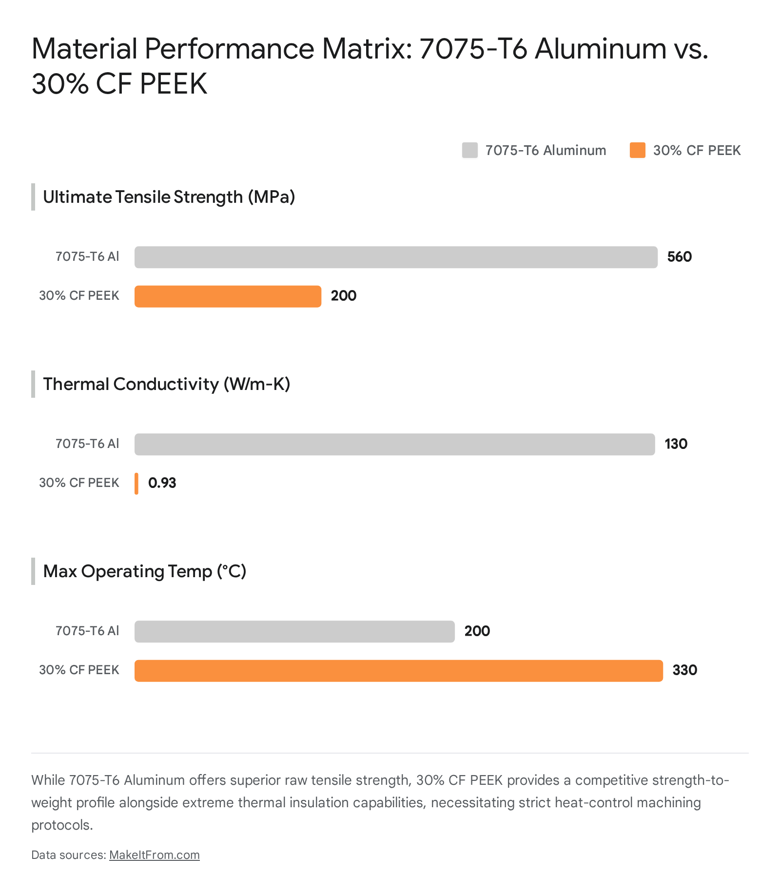
Aluminum 7075, specifically processed in the T6 temper, has rapidly become the default material specification for high-performance tactical receivers, modular chassis systems, and precision optics mounts.13 Alloyed primarily with heavy concentrations of zinc (5.6% – 6.1%), magnesium (2.1% – 2.9%), and copper, 7075-T6 offers a tensile strength profile that is formidable.38 It boasts an Ultimate Tensile Strength (UTS) of approximately 560 to 570 MPa, and a Yield Strength of roughly 505 MPa, allowing it to rival the strength characteristics of many heavy steel alloys, combined with a dramatically lower density.14 The “T6” designation indicates a specific thermal tempering process involving solution heat treating and artificial aging, which forms microscopic MgZn2 precipitates that lock the crystalline structure, massively increasing hardness and rigidity.38
However, 7075-T6 presents unique and severe machining challenges compared to the softer, highly formable, and more ubiquitous 6061 aluminum alloy.13 While it generally machines cleanly, its extreme strength generates significant cutting forces that stress machine spindles and cutting tools.13 The optimal machining philosophy for 7075-T6 revolves around aggressive high-speed cutting (high surface feet per minute – SFM) combined with heavy chip loads. This strategy purposefully utilizes the material’s excellent thermal conductivity (approximately 130 W/m-K) to evacuate the immense heat generated by friction rapidly through the ejected chip, rather than allowing the thermal energy to soak into the workpiece or degrade the cutting tool edge.15
Absolute rigidity in both the machine spindle and the workholding (such as the aforementioned deep dovetail fixtures) is paramount; any lack of rigidity or micro-vibration during heavy roughing passes will immediately manifest as poor, chattered surface finishes and exponentially accelerate catastrophic tool wear.25 Furthermore, advanced manufacturing facilities are increasingly exploring cryogenic machining techniques. Studies utilizing cryogenic CO2 as a cutting fluid for 7075-T6, guided by Taguchi’s L9 orthogonal array for parameter optimization, have demonstrated superior results compared to traditional flood coolant, significantly reducing built-up edge (BUE) on tools and improving surface roughness to an optimal 0.736 µm.42
5.2. The Integration of Polyetheretherketone (PEEK) and PEEK-GF30
While 7075-T6 aluminum elegantly addresses requirements for structural rigidity and impact resistance, components exposed to extreme, sustained heat, or those requiring absolute electrical and thermal insulation, are transitioning rapidly to high-performance thermoplastics. The undisputed leader in this category is Polyetheretherketone (PEEK).16 PEEK is a semi-crystalline engineering polymer capable of maintaining its exceptional mechanical properties at continuous operating temperatures up to 250°C (482°F), with a melting onset (solidus) pushing near 340°C.15
In tactical applications, unfilled PEEK is extensively utilized for heat shields, suppressor covers, and internal trigger group components. In these roles, it acts as a phenomenal thermal insulator, preventing the extreme heat generated by rapid, sustained weapon fire from transferring to the operator’s hands or permanently damaging sensitive, heat-intolerant electro-optics.16 Furthermore, its inherent chemical resistance allows it to withstand highly corrosive gun cleaning solvents and propellent residues that would rapidly degrade lesser plastics or pit unprotected metals.16
For tactical components requiring stiffness and tensile strength closer to metallic levels, engineers utilize glass-filled or carbon-filled variants, specifically PEEK-GF30 (30% glass fiber reinforcement) or 30% CF PEEK (Carbon Fiber).17 While these specialized reinforcements exponentially increase the material’s elastic modulus and overall strength-to-weight ratio, they create a highly hostile, abrasive environment for CNC cutting tools.15
5.3. Tooling and Feed Strategies for Abrasive Polymers
The machining philosophy for PEEK, and especially PEEK-GF30, is the exact, polar antithesis of the high-speed approach utilized for aluminum. Machining PEEK is defined by strict, unyielding Heat Control.15 PEEK possesses exceptionally low thermal conductivity (ranging from merely 0.25 to 0.93 W/m-K, a fraction of aluminum’s 130 W/m-K).41 Consequently, the extreme heat generated by the mechanical friction of the cutting tool does not evacuate through the plastic chip; instead, it concentrates fiercely at the cutting edge and soaks directly into the workpiece surface.44 If PEEK is machined too aggressively, localized melting, severe micro-cracking, and macroscopic warping caused by the sudden relief of internal material stresses will instantly ruin the dimensional integrity of the part.15
The introduction of 30% glass fibers in PEEK-GF30 drastically exacerbates this thermal issue by acting like a highly abrasive, fine-grit sandpaper against the spinning tool.17 Standard uncoated solid carbide tools are rapidly destroyed in minutes. To machine PEEK-GF30 successfully and economically, engineers must employ specialized Polycrystalline Diamond (PCD) tooling, or at minimum, high-end diamond-coated carbide, which provides unparalleled wear resistance against the glass substrate.17
Furthermore, cutting speeds (SFM) must be drastically reduced by 30% to 50% compared to the speeds used for unfilled PEEK to actively manage and suppress heat generation.17 Feed rates (IPR), however, must be maintained or only slightly reduced to ensure the tool continues to shear the material rather than rubbing against it, which would induce further friction and cause the tool edge to chip.17
Crucially, the use of a high-volume, high-pressure flood coolant system is absolutely non-negotiable.17 In PEEK-GF30 machining, the coolant serves critical dual purposes: it acts as a vital heat sink to extract thermal energy and prevent polymer melting, and more importantly, it aggressively flushes the highly abrasive glass shards away from the cutting zone. Without robust, high-pressure chip evacuation, the microscopic glass fragments become trapped between the tool flank and the workpiece, acting as a destructive grinding paste that pulverizes the tool edge and obliterates the dimensional accuracy and surface finish of the component.17 Additional post-machining annealing processes are often required to relieve induced stresses, particularly in thin-walled components prone to deformation.17
| Material Specification | Ultimate Tensile Strength (MPa) | Thermal Conductivity (W/m-K) | Machining Philosophy | Critical Tooling Requirement |
| 7075-T6 Aluminum | ~560 – 570 | ~130 | High-speed cutting, aggressive feed. Evacuate heat through chip. | Standard carbide; extreme machine spindle rigidity required. |
| Unfilled PEEK | ~97 – 100 | ~0.25 | Heat control. Prevent localized melting. Moderate SFM. | Extremely sharp carbide tools to shear plastic cleanly. |
| PEEK-GF30 / 30% CF PEEK | ~200 | ~0.93 | Extreme heat control. High-pressure flood coolant mandatory to clear abrasive dust. | Polycrystalline Diamond (PCD) tooling to survive glass/carbon abrasion. |
6. Software Architectures: AI, Digital Twins, and Metrology-Driven QA
The sophisticated physical hardware of 5-axis machining centers and sub-micron 3D scanners is ultimately governed, optimized, and connected by the sophistication of its underlying software architecture. By 2026, the defense manufacturing industry has fully transitioned toward integrated, AI-assisted computer-aided manufacturing (CAM) environments that optimize toolpaths and predict failures long before a physical chip is ever cut.45
6.1. Mastercam 2026.R2 and AI-Enabled Toolpath Optimization
The geometric and mathematical complexity of programming simultaneous 5-axis movements, managing three linear axes and two rotational axes while simultaneously tracking the exact location of the tool tip, the geometry of the tool holder, and the bulk of the machine spindle to prevent catastrophic, high-velocity collisions, historically required months, if not years, of highly specialized programmer training.20 Software platforms like Mastercam 2026.R2 have integrated advanced computational tools to effectively mitigate this high barrier to entry.45
A critical feature in modern programming is GPU-accelerated simulation. Before a G-code program is exported and sent to the physical CNC machine, the entire cutting process, including the exact machine kinematics, workholding, and raw stock, is simulated in a virtual “digital twin” environment.45 Mastercam 2026.R2 utilizes the Graphical Processing Unit (GPU) to deliver these complex simulations up to ten times faster than legacy CPU-based software.45 This immense processing speed allows programmers to rapidly iterate and visually identify microscopic gouges, verify the surface finishes generated by complex Swarf milling algorithms, and confirm that collision avoidance algorithms are operating correctly in high resolution, without sacrificing programming time.45
Furthermore, the introduction of genuine AI-enabled CAM intelligence, such as Mastercam Copilot, has fundamentally streamlined workflow generation.45 These intelligent systems analyze the selected material properties (such as recognizing the highly abrasive nature of PEEK-GF30 versus the thermal dynamics of 7075-T6) alongside the specific geometry of the selected tool. The AI then automatically suggests mathematically optimal feed rates, spindle speeds, and step-over algorithms.45 This ensures that SMEs can safely machine exotic materials and highly complex geometries with optimized parameters on the first attempt, drastically reducing the costly trial-and-error scrap historically associated with multi-axis programming. Additionally, these smart machines are increasingly connected via the Internet of Things (IoT), providing real-time monitoring of spindle health, tool wear, and predictive maintenance schedules, further minimizing unplanned downtime.1
6.2. Metrology-Driven Quality Assurance and Closed-Loop Manufacturing
The production loop between digital design and physical manufacturing is definitively closed by integrated metrology. The exact same point-cloud data principles and hardware utilized in reverse engineering are applied directly to quality assurance through First Article Inspection (FAI).10 Once a 5-axis machine produces the first physical part of a new production run, it is immediately subjected to high-resolution optical scanning or tactile Coordinate Measuring Machine (CMM) probing.10
The resulting, highly accurate digital scan of the manufactured part is then digitally overlaid onto the original parametric CAD model to generate a precision, color-coded deviation map.49 This topological map instantly highlights any microscopic areas where the physical part deviates from the digital engineering intent, deviations that may occur due to tool deflection during a heavy roughing pass, thermal expansion of the aluminum workpiece during machining, or internal stress relief in polymer parts.25
This immediate, highly visual, and data-rich feedback loop allows manufacturing engineers to execute micro-adjustments to the CNC toolpaths or cutter compensation values. This ensures that all subsequent parts in the production run adhere perfectly to the strict Geometric Dimensioning and Tolerancing (GD&T) required by aerospace and defense quality standards, such as AS9100 and ISO 9001, effectively guaranteeing a zero-defect rate.5
7. SME Case Studies: Competing with Tier-One Defense Contractors
The synergistic integration of 5-axis automation, AI-driven CAM software, and sub-micron reverse engineering has fundamentally altered the competitive economic landscape of defense manufacturing. Historically, the immense cost of technological entry, coupled with the burden of strict regulatory compliance, restricted complex defense contracts almost exclusively to massive tier-one prime contractors. However, utilizing commercial-off-the-shelf (COTS) 5-axis centers paired with robust robotic automation, highly agile regional SMEs are successfully capturing significant market share. This trend is highly visible in Michigan’s advanced manufacturing sector, a dense industrial cluster often referred to as “Automation Alley”.6
7.1. Prosper-Tech Machine & Tool: Automation and Defense Integration
Prosper-Tech Machine & Tool, operating out of Richmond, Michigan, exemplifies the capabilities of the modern, highly lethal defense SME.5 Certified to AS9100 and ISO 9001, ITAR registered, and strictly compliant with NIST 800-171 and CMMC Level 2 cybersecurity frameworks, the company has strategically positioned itself to handle highly sensitive, mission-critical government technical data packages.5
To compete effectively on both production volume and unit price against vastly larger entities, Prosper-Tech leverages intensive machine automation. By integrating hardware such as an Erowa Robot Compact 80 with their 5-axis milling centers, the company achieves true “lights-out” manufacturing.5 This advanced robotic pallet-changing system automatically loads raw material billets and unloads finished components without human intervention, allowing the multi-axis machines to run continuously unattended through the night and over weekends.1
This relentless automation drastically increases spindle uptime and amortizes the hourly machine rate over a significantly larger volume of parts. Consequently, this enables SMEs like Prosper-Tech to offer highly competitive pricing and rapid surge support on complex tactical housings, armor components, casted aerospace parts, and brackets for major entities like the U.S. Army DEVCOM-AC Picatinny Arsenal and the Defense Logistics Agency.5 Their strategic joint venture, Mettle Craft Manufacturing, further solidifies their capacity to handle multi-million dollar “Build-to-Print” government contracts.5
7.2. Kimastle and Owens Industries: Cross-Industry Precision Migration
SMEs are also aggressively cross-pollinating their deep technical expertise from ultra-strict, low-tolerance sectors like aerospace to elevate the baseline quality of tactical accessories. Owens Industries, operating out of the broader Michigan aerospace corridor, initially built its formidable reputation by machining micron-tolerance bicep assemblies and robotic joints for NASA’s Robonaut project utilizing specialized 5-axis CNCs.52 They have subsequently translated this high-stakes, zero-failure aerospace discipline directly into the manufacturing of tactical arms components. By applying the exact same rigid thermal stability controls, dynamic toolpath optimization, and strict material traceability required for space-flight hardware, they ensure defense components perform flawlessly in theater.52
Similarly, Kimastle, based in Chesterfield, Michigan, utilizes continuous 5-axis milling, backed by full Coordinate Measuring Machine (CMM) inspection support, to produce complex weaponry and vehicle implements for the U.S. Marine Corps Training and Education Command (TECOM).48 By finishing complex components in significantly fewer setups utilizing the 9-to-2 methodology, Kimastle guarantees the extreme geometric repeatability and absolute zero-defect rates demanded by modern military contracts. This cross-industry migration proves that agility, combined with advanced technology, can consistently outmaneuver the bureaucratic inertia of traditional tier-one contractors.48
| Michigan SME | Core Technological Capability | Key Defense / Aerospace Application | Certifications / Strategic Advantage |
| Prosper-Tech Machine & Tool | 5-Axis Milling paired with Erowa Robot Compact 80 for “lights-out” automation. | Precision tactical housings, armor components, casted parts for DEVCOM-AC. | AS9100, ISO 9001, ITAR, CMMC Level 2. High-volume surge capacity via Mettle Craft JV. |
| Owens Industries | Ultra-precision 5-Axis machining with strict thermal and dynamic stability controls. | Translated NASA Robonaut micron-tolerance expertise to tactical components. | Aerospace-grade precision applied to defense manufacturing. |
| Kimastle | 3, 4, and 5-Axis milling with full CMM verification and plastic welding integration. | Weaponry and military vehicle implements for USMC TECOM. | High repeatability, reduced setups, rapid prototyping to production execution. |
| Eagle Group | High-resolution 3D Laser Scanning and Parametric Reverse Engineering. | Rapid recreation of undocumented legacy components (e.g., MiG-17F fuel cap). | On-demand sustainment of aging military platforms without OEM blueprints. |
7.3. Eagle Group: Rapid Reverse Engineering of Legacy Components
The strategic, logistical advantage of 3D scanning is prominently displayed in the sustainment and modernization of legacy military platforms. Many defense systems currently in operation utilize complex components that were designed decades before the advent of 3D CAD modeling. When a critical spare part is required, there is often no digital blueprint available, and the original casting or machining tooling has long been destroyed or lost.2
The Eagle Group, based in Muskegon, Michigan, vividly demonstrated the sheer power of digital metrology by successfully reverse engineering a highly complex fuel cap for a legacy MiG-17F fighter jet in merely two days.17 Utilizing high-resolution 3D laser scanning, engineering teams entirely bypassed weeks of painstaking manual drafting, caliper measurements, and physical prototyping. The scanner captured the intricate geometries, internal threads, and locking mechanisms of the original physical artifact, generating a pristine digital mesh. This mesh was rapidly converted into a parametric solid model ready for CAM programming and immediate manufacturing.17
This specific capability to resurrect undocumented hardware on-demand is increasingly vital for the tactical accessories sector. It allows highly capable SMEs to rapidly produce modernization kits, precision optics mounts, and ergonomic upgrades for aging small arms inventories without ever needing to rely on Original Equipment Manufacturer (OEM) technical data packages, thereby ensuring supply chain independence and rapid deployment to the warfighter.2
8. Strategic Implications and Future Outlook
The forceful convergence of simultaneous 5-axis CNC machining, high-resolution 3D scanning metrology, and advanced material science is fundamentally and permanently restructuring the small arms and tactical accessories industry in 2026. By condensing historically complex, error-prone 9-step manufacturing sequences into highly automated, continuous 2-step processes utilizing dovetail fixturing, manufacturers have drastically reduced lead times, compressed prototyping costs by upwards of 30%, and structurally eliminated the geometric inaccuracies inherent in manual refixturing. The widespread adoption of complex, continuous toolpaths, such as simultaneous Swarf milling, has perfectly optimized the thermodynamic and acoustic dynamics of integrated suppressor monocores, while sub-micron reverse engineering has enabled unprecedented, biologically optimized levels of ergonomic customization.
Simultaneously, the aggressive transition toward aerospace-grade 7075-T6 aluminum and high-temperature, glass-filled engineering polymers like PEEK-GF30 has yielded tactical components that are drastically lighter, structurally stronger, and immensely more thermally resilient than their steel predecessors. Mastering the highly divergent and technically demanding machining philosophies required by these specific materials, balancing the extreme high-speed roughing capabilities of aluminum against the strict thermal control and abrasive wear mitigation mandatory for reinforced polymers, now definitively separates industry leaders from the rest of the market.
Perhaps most significantly, these interconnected, heavily automated technologies have deeply empowered a new class of agile SMEs to disrupt a sector traditionally controlled by monolithic defense primes. Utilizing lights-out robotic automation, AI-assisted CAM software, and closed-loop metrology, these specialized machine shops operate with vastly lower overhead, higher spindle utilization, and greater adaptive speed. As global supply chains continue to prioritize structural resilience and rapid, localized production capabilities, the advanced manufacturing architectures firmly established in 2026 ensure that the next generation of small arms and tactical accessories will be designed, optimized, and produced with an unprecedented degree of speed, efficiency, and absolute kinematic precision.
Please share the link on Facebook, Forums, with colleagues, etc. Your support is much appreciated and if you have any feedback, please email us in**@*********ps.com. If you’d like to request a report or order a reprint, please click here for the corresponding page to open in new tab.
Sources Used
- 5-Axis CNC Machining Trends to Watch at IMTS 2026 – Yamazen, accessed March 13, 2026, https://www.yamazen.com/about/news/post/5-axis-cnc-trends-imts2026
- 3D Scanning Enhances Efficiency and Accuracy in Reverse Engineering | Article | FARO, accessed March 13, 2026, https://www.faro.com/en/Resource-Library/Article/3D-Scanning-Efficiency-in-Reverse-Engineering
- medc-msf-fiscal-year-2020-annual-report.pdf – Michigan Economic Development Corporation, accessed March 13, 2026, https://www.michiganbusiness.org/4b0274/globalassets/documents/reports/legislative-reports/medc-msf-fiscal-year-2020-annual-report.pdf
- Manufacturing in America: A View from the Field – MIT Work of the Future, accessed March 13, 2026, https://workofthefuture-taskforce.mit.edu/document/2020-research-brief-berger-2/
- CNC Precision Machining for the Defense Industry – Prosper-Tech.net, accessed March 13, 2026, https://www.prosper-tech.net/defense-machine-shop
- “pAndeMoniuM” reignS At nAtionAl roboticS leAgue finAlS, accessed March 13, 2026, https://ntma.org/wp-content/uploads/2019/02/June13-Record-web-compressed.pdf
- Upgrading supply chain resilience: How can 5-axis CNC technology …, accessed March 13, 2026, https://www.thisdaylive.com/2026/01/01/upgrading-supply-chain-resilience-how-can-5-axis-cnc-technology-reduce-the-cost-of-customized-parts-by-30/
- Reverse-Engineering an Incredibly Difficult to Machine Hand Grip …, accessed March 13, 2026, https://www.youtube.com/watch?v=b1EQoIK76fc
- Why 5-Axis CNC Machining is Key for Defense Parts, accessed March 13, 2026, https://staubinc.com/news/why-5-axis-machining-for-defense-components/
- Gun Design Solutions: 3D Scanning and Reverse Engineering, accessed March 13, 2026, https://3d-engineering.net/engineering-services/firearms-explosives/gun-design/
- 3D Scanning and Reverse Engineering a Handgun Grip …, accessed March 13, 2026, https://3dscanningservices.net/project/3d-scanning-reverse-engineering-handgun-grip/
- Additive Manufacturing (AM) in Expeditionary Operations: Current Needs, Technical Challenges, and Opportunities – DTIC, accessed March 13, 2026, https://apps.dtic.mil/sti/tr/pdf/AD1026571.pdf
- Best Aluminum for Machining: How To Choose the Right Alloy for CNC Parts, accessed March 13, 2026, https://www.c-hmachine.com/aluminum/best-aluminum-for-machining
- 7075 Aluminum Bar in Aerospace & Defense Sector – Zetwerk, accessed March 13, 2026, https://www.zetwerk.com/en-us/resources/knowledge-base/aluminum-extrusions/7075-aluminum-bar-the-aerospace-and-defense-industrys-go-to-material/
- When to Choose PEEK Over Aluminum: The Ultimate 2025 Guide, accessed March 13, 2026, https://www.zenithinmfg.com/peek-vs-aluminum-guide/
- 5 Advantages of PEEK Versus Metals – AIP Precision Machining, accessed March 13, 2026, https://aipprecision.com/5-advantages-of-peek-versus-metals/
- The Ultimate Guide to PEEK Machining Techniques – ptsmake, accessed March 13, 2026, https://www.ptsmake.com/the-ultimate-guide-to-peek-machining-techniques/
- Do More With Less: 5-Axis Machining – Productivity Inc, accessed March 13, 2026, https://www.productivity.com/do-more-with-less-5-axis-machining/
- CNC Machines: 3- vs. 4- vs. 5-Axis | Prototek, accessed March 13, 2026, https://prototek.com/article/cnc-machines-3-axis-vs-4-axis-vs-5-axis/
- Five Axis Machining: Complete Guide to Advanced CNC Tech, accessed March 13, 2026, https://gimbelautomation.com/a/blog/mastering-five-axis-machining-techniques-and-advantages-explained
- 5-Axis Glossary: Terms You Need to Know – Okuma, accessed March 13, 2026, https://www.okuma.com/blog/5-axis-glossary
- 5 Ways to Improve Productivity with 5-axis Machining – mastercam.com, accessed March 13, 2026, https://www.mastercam.com/community/blog/5-ways-to-improve-productivity-with-5-axis-machining/
- 10 Leading cnc machine companies of 2026 | Expert Insights – Mekalite, accessed March 13, 2026, https://mekalite.com/10-must-know-cnc-machine-companies-in-2026-that-define-innovation/
- 5-Axis Online GROB-Webinar Series, accessed March 13, 2026, https://www.grobgroup.com/en/5-axis-online-a-grob-webinar-series/
- Aerospace CNC Machining: How to Ensure Quality & Reduce Costs? – ptsmake, accessed March 13, 2026, https://www.ptsmake.com/aerospace-cnc-machining-how-to-ensure-quality-reduce-costs/
- CNC Machine Tools Market Outlook to 2035 – IndexBox, accessed March 13, 2026, https://www.indexbox.io/blog/cnc-machine-tools-market-to-2035-driven-by-industry-4-0-and-smart-factory-integration-demands/
- The Ultimate CNC Machining Glossary | MakerVerse, accessed March 13, 2026, https://www.makerverse.com/resources/cnc-machining-guides/the-ultimate-cnc-machining-glossary/
- How 5-Axis Machining Reduces Setups and Improves Accuracy – Norck, accessed March 13, 2026, https://www.norck.com/blogs/news/how-5-axis-machining-reduces-setups-and-improves-accuracy
- An Ergonomic Customized-Tool Handle Design for Precision Tools using Additive Manufacturing: A Case Study – MDPI, accessed March 13, 2026, https://www.mdpi.com/2076-3417/8/7/1200
- ERGONOMIC GRIP DESIGN CONSIDERATIONS – Avient, accessed March 13, 2026, https://www.avient.com/sites/default/files/2021-11/avient-design-ergonomic-design-guide.pdf
- How to Use 3D Scanning and 3D Printing for Reverse Engineering | Formlabs, accessed March 13, 2026, https://formlabs.com/blog/how-to-use-3d-scanning-and-3d-printing-for-reverse-engineering/
- Case Study – Reverse Engineering an AR-10 Rifle from Scan Data – Polyga, accessed March 13, 2026, https://www.polyga.com/case-studies/reverse-engineering-ar-10-rifle-scan-data/
- Suppressor Baffle Machining – The Hobby-Machinist, accessed March 13, 2026, https://www.hobby-machinist.com/threads/suppressor-baffle-machining.79842/
- Generate a swarf toolpath | Autodesk, accessed March 13, 2026, https://www.autodesk.com/learn/ondemand/tutorial/generate-a-swarf-toolpath
- Swarf Machining, 5 Axis, accessed March 13, 2026, https://mecsoft.com/OnLineHelp/RhinoCAM%202023/5thaxisswarfmachining.html
- Swarf – Mastercam, accessed March 13, 2026, https://www.mastercam.dk/docs/hsmpp/StrategySwarf.html
- How CNC Machining is Shaping the Future of Firearms Manufacturing – Mitotec Precision, accessed March 13, 2026, https://www.mitotecprecision.com/how-cnc-machining-is-shaping-the-future-of-firearms-manufacturing/
- 7075 Aluminium – The Ultimate Guide – Custom Precision Component Provider | TOPS, accessed March 13, 2026, https://topsbest-precision.com/blog/7075-aluminium-the-ultimate-guide/
- 30 CF PEEK vs. 7075-T6 Aluminum – MakeItFrom.com, accessed March 13, 2026, https://www.makeitfrom.com/compare/30-Percent-Carbon-Fiber-30-CF-PEEK/7075-T6-Aluminum
- development of cast and heat treated 7075 alloy rifle receiver, accessed March 13, 2026, https://etd.lib.metu.edu.tr/upload/12618726/index.pdf
- 7075 Aluminum vs. PEEK – MakeItFrom.com, accessed March 13, 2026, https://www.makeitfrom.com/compare/7075-AlZn5.5MgCu-3.4365-2L95-A97075-Aluminum/Polyetheretherketone-PEEK
- Evaluation of Machining Parameters in Turning Al7075-T6 Aluminum Alloy Using Dry, Flooded, and Cryogenic Cutting Fluid Conditions – MDPI, accessed March 13, 2026, https://www.mdpi.com/2504-4494/9/10/328
- high-temperature polymers: transforming aerospace engineering – AIP Precision Machining, accessed March 13, 2026, https://aipprecision.com/high-temperature-polymers-transforming-aerospace-engineering/
- How to Optimize PEEK CNC Machining with Proper Tools, Parameters and Annealing, accessed March 13, 2026, https://www.peekchina.com/blog/peek-cnc-machining.html
- Mastercam 2026.R2: Power, Precision, and Productivity Redefined, accessed March 13, 2026, https://www.mastercam.com/community/blog/mastercam-2026-r2-power-precision-and-productivity-redefined/
- Mastercam 2026 Delivers Superior Machining Performance with Advanced Productivity Tools and AI-enabled CAM Intelligence, accessed March 13, 2026, https://www.mastercam.com/about/media/mastercam-2026-delivers-superior-machining-performance/
- Future Trends in 5-Axis CNC Machining You Need to Know, accessed March 13, 2026, https://dkeng.com.au/future-trends-5-axis-cnc-machining/
- Defense Industry – Kimastle, accessed March 13, 2026, https://www.kimastle.com/defense-industry-michigan/
- 3D scanning applications are transforming aerospace manufacturing, accessed March 13, 2026, https://blog.manufacturing.hexagon.com/metrology-measurement/metrology-software/3d-scanning-applications-transforming-aerospace-manufacturing/
- KR QUANTEC against electrical waste – International Federation of Robotics, accessed March 13, 2026, https://ifr.org/case-studies/collaborative-robots/stihl-opens-up-new
- ACCELERATING INNOVATION VIA INDUSTRY-SCALE OPEN INNOVATION NETWORKS – Clemson OPEN, accessed March 13, 2026, https://open.clemson.edu/cgi/viewcontent.cgi?article=1849&context=all_dissertations
- Michigan CNC Machine Shop for Aerospace Parts: Get a Quote | Owens Industries, LLC, accessed March 13, 2026, https://www.owensind.com/MachineShop/Michigan/Aerospace
- Miracle in Muskegon: How the Eagle Group Replicated a MiG 17F …, accessed March 13, 2026, https://blog.eaglegroupmanufacturers.com/miracle-in-muskegon-how-the-eagle-group-replicated-a-mig-17f-fighter-jet-fuel-cap-in-two-days