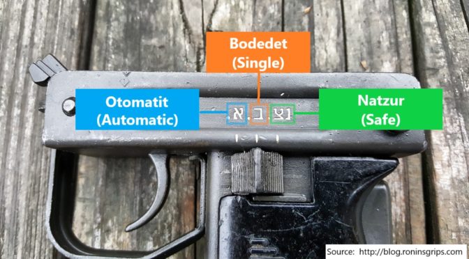
When the Israeli Defense Force (IDF) adopted the Uzi, they had the selector markings written in Hebrew script. For those of us that can’t read Hebrew, I did some digging as to the translation:
As you can see labelled in the above photo, we have each position marked with the Hebrew term in its romanized form as well as the English translation.
Left position: Otomatit is fully automatic
Center position: Bodedet is single fire / semi-automatic
So the semi-auto 9mm Uzi carbine build has the Molyresin applied and is ready to go together. The following is an overview of the final assembly steps:
1] Install the grip frame assembly. Insert the tip first and swing the back up into position. Install the grip frame takedown pin. If the assembly will not go into position you may need to remove the bolt safety. The McKay receiver and bolt do not use that part. If you have questions about the grip assembly and preparing it for semi-auto use, click here.
2] Install the stock bracket with its 1/4″ screw and then the stock itself with its three screws taking care to use the correct bit on the slotted screws. Make sure the bolt doesn’t stick in too far. If you have questions about converting the quick detach stock to be permanently attached, click here.
4] I installed the barrel nut catch and spring plus the front sight. Slide the catch far enough back that it hooks the receiver and does not come back out.
5] I then installed the rear top cover catch and rear sight. The trick here is to push down on the flip sight while pushing the screw through so the threads can engage on the other side. The little tiny but just locks it in place – the receiver itself is threaded also. Note, I did have an issue with either the thread on the bolt or the receiver. I could not get the rear sight screw to enter on the opposite threaded side. After playing with it for a few minutes it dawned on me that either the screw or the threading in the “ear” of the receiver could be messed up so I installed the screw from the opposite direction just to chase the threads real quick and that solved whatever the problem was because when I then tried to insert it the correct way, the screw went right in.
6] Rather than mess with rivets, I tapped the front sling for a #10-28 screw. I sanded down the head of the screw to avoid interference with the bolt and then applied medium Loctite to the thread when i installed it. If you need to remove more of the screw head later it can be readily reached with a Dremel and a flap sander or whatever bit you wish.
7] The 16″ semi-auto barrel slide right into the front trunnion and into the ring of the semi-auto feed ramp. Rather than use the barrel nut, I opted for a very cool two piece barrel shroud from Title II Arms. It is solid aluminum and exceptionally well made. Note, I show a light on a rail adapter on the bayonet lug. It looks cool but I actually removed it as my hand’s natural hold runs right into it. It’s not a reflection of the CAA rail but it’s just not for me. With it gone, my hand can go right out to the end of the handguard and is much more comfortable.
8] Next it was time to sort out the striker fired bolt system. This raises a critical legal point –the weapon must fire from a closed bolt. This means you can’t use the original open bolt. After some digging, I decided to use the McKay closed semi-auto bolt system for my build. Now McKay components are popular and they were out of stock on the complete bolt assembly but Robert RTG had it in stock so I bought it and other parts from them. As of my writing this, for example, McKay has their receivers in stock, bolt assembly but not the barrel so you can check between both firms plus McKay says they sell to Sarco and Apex.
9] I had to do some reading to figure out how the bolt went together as I had never seen anything quite like it before. The best write-up I could find that really helped me is right here. In a nut shell, take your original bolt, push out the extractor retaining pin and then push the extractor straight out the front of the bolt. From the rear, the extractor looks like a screw due to the slotted head but it is not. The slot is there to make it easy for you to rotate the extractor into position. Insert the extractor into the new semi-auto bolt. You will notice that with your semi-auto bolt a small blocking latch and pin are included just like you would see in the Uzi Pro Pistol – indeed, the whole bolt assembly is very similar to the Uzi Pro Pistol if you look it up. The little spring and the latch are inserted into the bolt and held in place by the extractor pin in the semi-auto bolt.
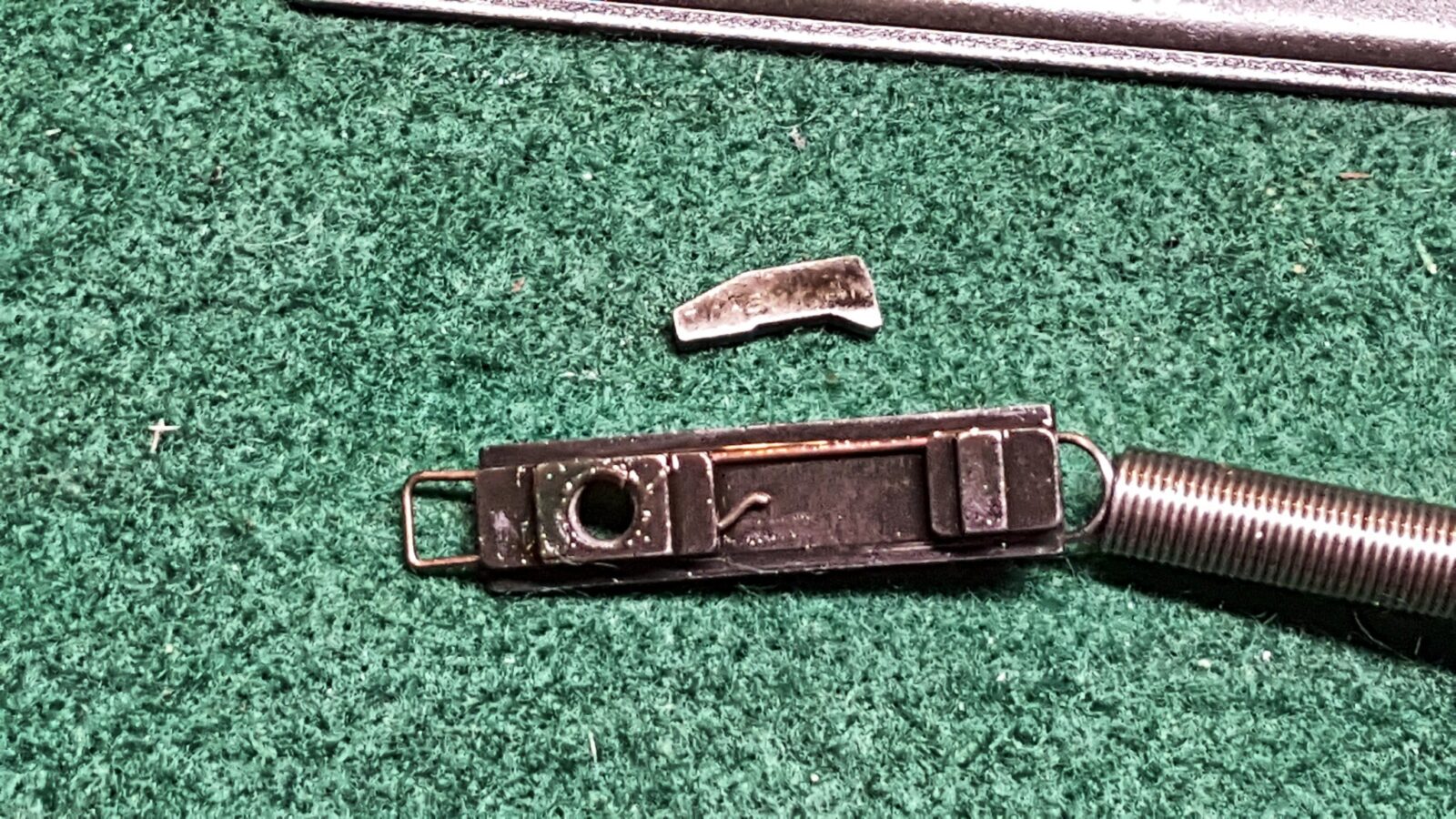
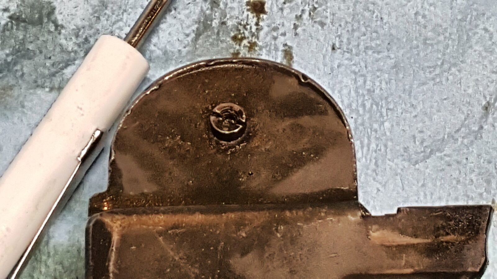
Ok – this next photo shows a problem that I didn’t find out until the first trip to the range. At the lower right of bolt is a pin that holds the extractor in place plus you can see a tab sticking down – that is the locking latch. Now look at the striker. You can’t see clearly but it is a half moon shape and I have it installed backward. The notch, or part of the striker’s base that is missing should be what goes against the bolt blocking latch. If you get it backward the weapon will not fire and you’ll notice the striker base getting beaten up by the latch.
Here’s the blocking latch – see how the bottom part stocks out? That is what will need to clear the notch when it is depressed during normal operation.
Here’s what it should look like – note how the striker bar has a smooth side and one with a relieved/depressed surface? The notched striker base goes towards the smooth portion:
Here you can see the base that is towards the relieved/depressed area plus you can see the blocking latch will let the striker come forward only if the latch is depressed. The chewed up area on the striker is from my mistaken assembly and a ton of testing trying to figure out what I did wrong.
Here’s another angle. The striker can only travel forward if that blocking latch is depressed – in the photo, the latch would be pushed down out of the way. In the Uzi with the bolt oriented the normal way, we would say the latch is being pressed upward.
Last pic:
10] If you look at the above photo, the striker system. The lower L-shaped bracket is the “Striker Guide”. Thestriker spring base and the striker are held in place by a roll pin. The return spring slides over the striker spring base as shown above.
11] Take the guide rod and spring from the kit and snip the fiber square board off the end. I used diagonal cutters and when I made my first cut the little board fell right off.
12] You then insert the recoil spring into the bolt and rotate the firing pin base while inserting the assembly into the bolt. The white is Tetra Firearm Grease. If it slides, grease it. If it rotates, oil it. You want this system to be well lubed to help it wear in.
13] Here is the whole bolt assembly with the recoil buffer at the end. Now this assebly is slid into the Uzi buffer end first. It takes some maneuvering to the recoil block into the rear and then the bolt nestles down.
14] The top cover is then installed. I used a 120 grit flap sander bit to slightly bevel my top cover to the catch can close and the top is really tight. The top black cover has the bevel in the photo below – it doesn’t take much. If you have any questions about what needs to be done to prepare the top cover for semi-auto use, click here.
14.1 – Added 7/2/18: I found out that you really need to fit the top cover. If you take a feeler gauge, you should be able to insert a 0.005 gauge between the bolt body and the top cover at the ejection port and meet little to no resistance. However, if you insert a 0.015 gauge, you should feel some resistance – not a complete stop but firm resistance. At 0.005, the gap is too small and you risk the bolt body binding and not travelling fast enough or far enough resulting in ejection and feed problems. The cover is very easy to adjust. I did a more detailed blog about testing and adjusting the cover – click here.
15] Now function test it to be safe. Do this with the weapon unloaded!!
Try to move the selector switch to Full Auto, which is all the way forward. It must not be able to move past semi-auto. If it does slide to the forward full auto position, you must fix it. If you haven’t done so, you need to install or fix your blocking tab that should be welded in the grip frame – click here for details. If you welded in a blocking plate, it may be too thin or too short. Regardless, you must figure out what is going on and fix it immediately. The ATF says the selector must not move into the full auto position.
Move the selector to semi-auto (the middle position), hold the grip safety, cock the weapon and squeeze trigger – you should here it dry fire with a real solid clunk sound. Life is good. If there is a soft click, the striker system did not cock – check your sear to make sure it is protruding into the receiver.
Move the selector to semi-auto (the middle position), DO NOT hold the grip safety, cock the weapon and squeeze trigger – the weapon should not fire. The Uzi should only be able to fire if on semi-auto and the grip safety is held. Check your pins and that the grip safety bar is sliding properly.
Move the selector to safe (all the way to the rear), hold the grip safety, cock the weapon and squeeze the trigger – the trigger should be blocked and nothing should happen. Turn the safety off and the weapon should fire. If it does not, check the pins and the selector bar can move into position properly and block the trigger.
Last, move the selector to semi-auto, hold the grip safety, squeeze the trigger (do not release it) and cock the weapon while holding the trigger in. We want to ensure the disconnector grabs the striker assembly. Now, release the trigger and squeeze it like normal. You should here it dry fire with a loud clunk sound and that is what you want. A light click is just the trigger and disconnector moving around and means the striker went back into battery vs. being retained. Something is off with the geometry – something is bent, you forgot to secure the grip frame with the takedown pin, etc.
If your Uzi passes the function tests, then proceed to test firing. I’d recommend securing the carbine in a stand and test firing with a string vs. holding the weapon. Also, only load one round in the magazine at a time and inspecting the carbine, especially the barrel, to make sure the first round fires and the case is ejected. Look for dings or tears in the case. Make sure the bullet didn’t get stuck in the barrel. If things are looking good, put two rounds in the magazine and test the overall cycling of the weapon. Again, check the case for any big gouges, scrapes, etc. When you are satisfied that the weapon is functioning correctly, then and only then try more and more rounds of ammo. I would go from one, to two, to three to five and to 10 before I tried a full clip. You do not want to have an uncontrolled full auto dump happen so carefully test the Uzi.
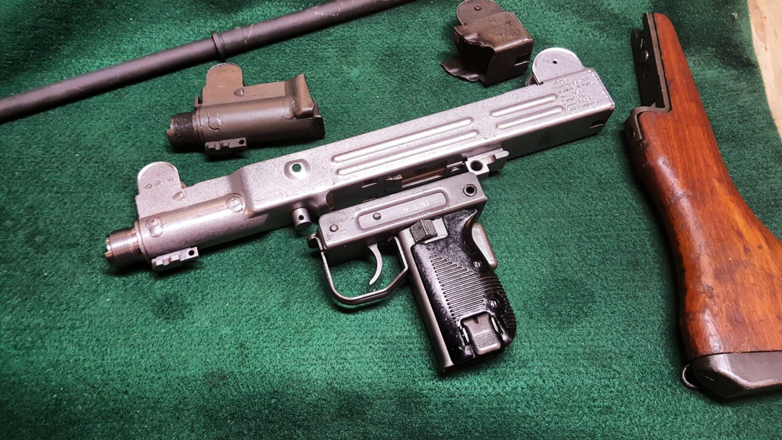
I had a lot of fun building mine. I added a Vortex Venom red dot that I really like so far plus an original Uzi green sling. Here are some photos and as mentioned the light and rail are off the weapon at this point.
I hope this helps and if you have any suggestions, please let me know.
I’ve used John Norrell’s Molyresin finish for years and like it. It’s easy to apply and quite durable. My preferred approach is to abrasive blast a steel surface, parkerize it and then apply the Molyresin and bake it on. There was one challenge this time though – it was below freezing and a snow storm was going on so I opted to just blast and apply the finish. This ought to hold up fairly well. With AKs, I am always fighting the selector lever scraping the receiver but don’t have that situation with an Uzi.
1] Clean everything with brake cleaner or acetone. I use a ton of brake cleaner. Also, be sure to wear nitrile gloves to avoid getting oil from your hands onto the clean parts.
2] Here’s a time-saving trick – the Uzi’s original parts were parkerized. Just clean anything with a good parkerized surface thoroughly but do not blast it off. If the “park” is worn away, proceed with blasting the surface. The reason is simple – parkerizing creates a surface that the Molyresin can really adhere to when baked on – even more so than blasting alone. Molyresin will not last if you just spray it on a smooth surface and bake it so don’t even consider doing that. In short, at least blast the part including all edges, corners, flat places, and so forth unless they are parked already. If you have the capacity to park parts [click here for a tutorial], do that and then apply the finish.
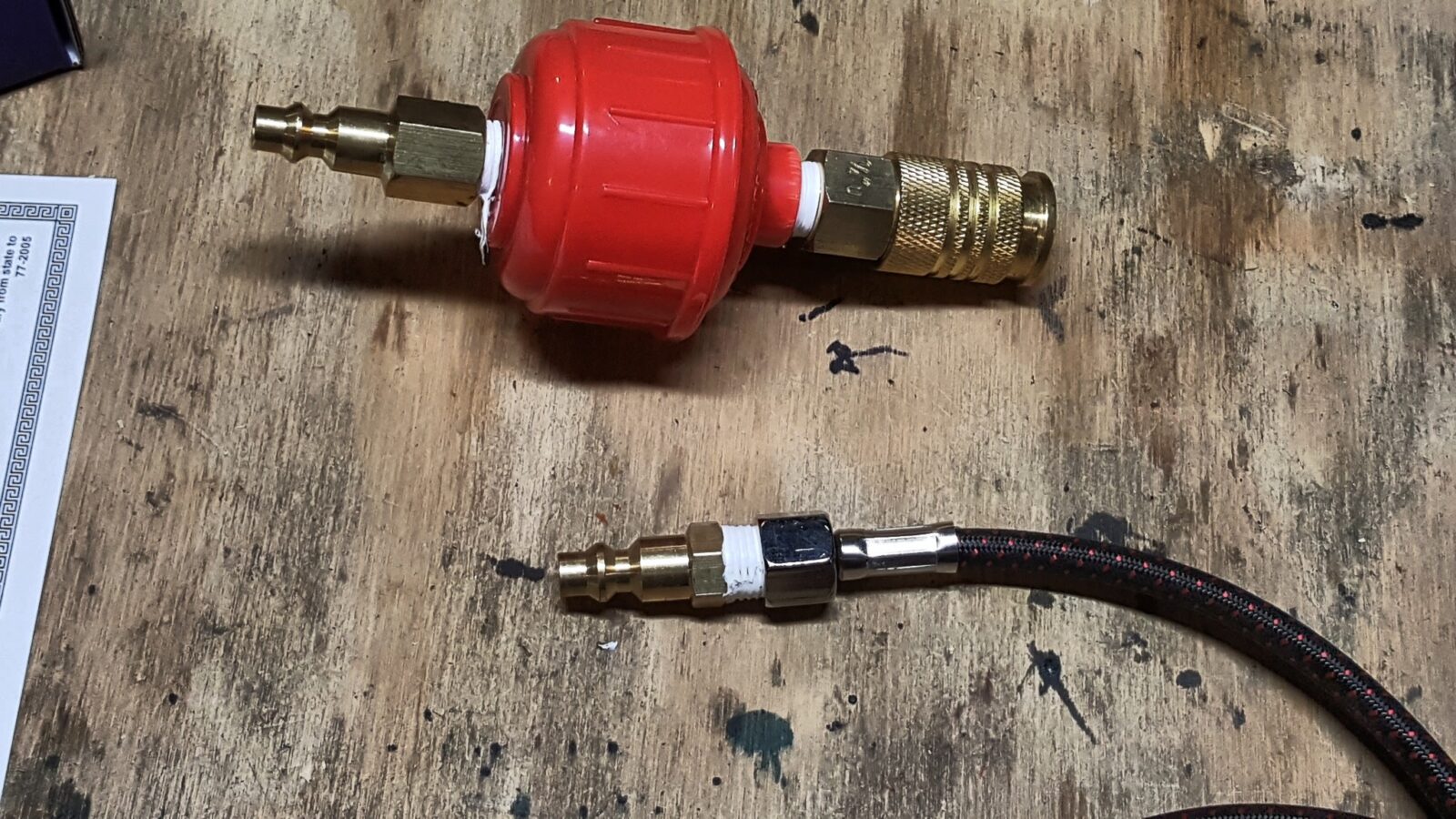
3] I used to use the Harbor Freight air brushes but have had a ton of problems with them failing so this year I invested in a nice Paasche H-series airbrush after hearing good things about them over the years. The quality is night and day better. I read a bunch of confusing junk on the Web about guys questioning how to hook up their air line. After buying the kit from Amazon, I simply applied quality PTFE tape to a male 1/4″ plug with a male 1/4″ NPT end and screwed to Paasche air line on to it. Done.
Paasche supplies a small bracket for holding the airbrush. I screwed it onto some scrap plywood so I can move it around as needed:
Also, I am really obsessive about clean air – I run a high-end filter system in my shop and still put a screw in filter just before the air brush’s air line just to play it safe. If you run your air brush off your home compressor, you definitely need to do this.
Another tip – don’t use cheap Teflon/pipe thread tape. I’ve had excellent luck with the following:
4] John has really good instructions online for applying Molyresin. I bought a quart of semi-gloss black for the Uzi build plus I plan on using it for a few other projects I have planned thus I bought the big bottle. They say an 8 oz bottle has enough Molyresin to coat 2.5 AR rifles. I used a tad over one ounce on the Uzi but I’m inefficient with my application because I am spraying all the little parts also. You have a ton of adjustments you can do when applying a finish via a paint brush so your actual coverage will vary. I have a simple theory though – I’d rather have left over finish than be in the middle of something and run out!
5] You need to preheat your parts to 150F. This allows the solvent to evaporate very quickly. Since the Uzi parts are all relatively small, I used my portable roaster oven that I bought at WalMart on sale. Oven thermostats are notoriously inaccurate so use a good thermometer to confirm the actual temperature. I use a Fluke 62 Max Plus due to my work with plastics and steel. My oven runs about 47 degrees cooler than what the dial heat setting claims for example. At any rate, I start preheating my parts while I get m airbrush ready. All the cleaning and surface prep is done at this point and I am wearing either nitrile gloves.
6] So, I used the size 1 tip that was installed in the Paasche brush and set the air pressure to 20 pounds and then dialed the tip in and out until I got the spray pattern that I wanted. One of the nice things about the Paasche is that the company stands behind their products – you can ask questions, lots of people have written about them and you can also download the manuals. I can tell you one thing, I am never going back t the Harbor Freight brushes now.
7] Shake the heck out of the Molyresin to get the settled pigment into suspension. Don’t just shake it once or twice – make sure the cap is on and shake vigorously for 20-30 seconds. Molyresin has pigments that are carried along with the solvent that must be deposited onto the metal and then baked into place. The liquid solvent is really just a carrier.
8] I apply the Molyresin in several coats until I have a uniform color everywhere. One trick I learned years ago is to take a cardboard box and cut slots in it to push in screws to paint their heads. Be sure to periodically shake your airbrush to keep the pigments in suspension.
9] For the barrel, I do install rubber plugs in the ends of the barrel to prevent finish from going inside. You can buy these tapered silicone rubber plugs from a variety of sources and reuse them. My current batch is from Amazon.
10] When you are done, clean the airbrush with MEK. One thing I do is to clean the little supply bottle first, fill the bottle with MEK and then blow in through the brush to clean the internals. Note, use MEK in a well ventilated area as you do not want to breath those fumes.
11] Place the parts in the oven at 300F for one hour to actually set the phenolic resin. This temperature is critical as nothing will happen if you heat to a lower temperature and you may affect the sheen of the finish if you go hotter. Again, use a good thermometer to make sure you are at or just over 300F – allow for the accuracy of your thermometer in other words. If your thermometer’s rated accuracy is +/- 1% then shoot for 303-305F for example or even a tad hotter but not less. The one hour is also a minimum. Boosting the temperature and reduce the time is not recommended.
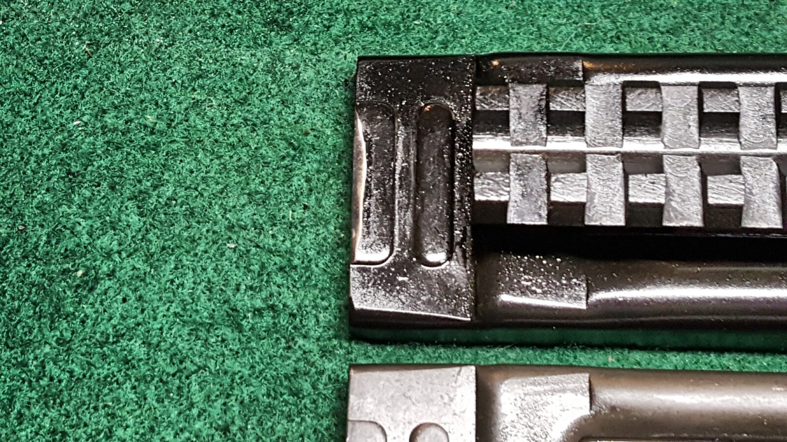
The Uzi’s top cover, what some call the dust cover, requires a slight modification for semi-auto use. The original cover has a ratcheting mechanism with a little finger called a “pawl” that slides down the cover when you pull it back but if you let go prematurely, the pawl catches in a notch and forward travel stops. Because a semi-auto bolt has a shorter distance to travel, there is not enough room for the ratchet mechanism to reset. The solution is very simple – remove the pawl.
Here’s a photo of my semi-auto top cover with a welded on picatinny rail that I bought from US Barrel Shrouds and really like. It’s already finished with a black Molyresin and in front of it is an original top cover.
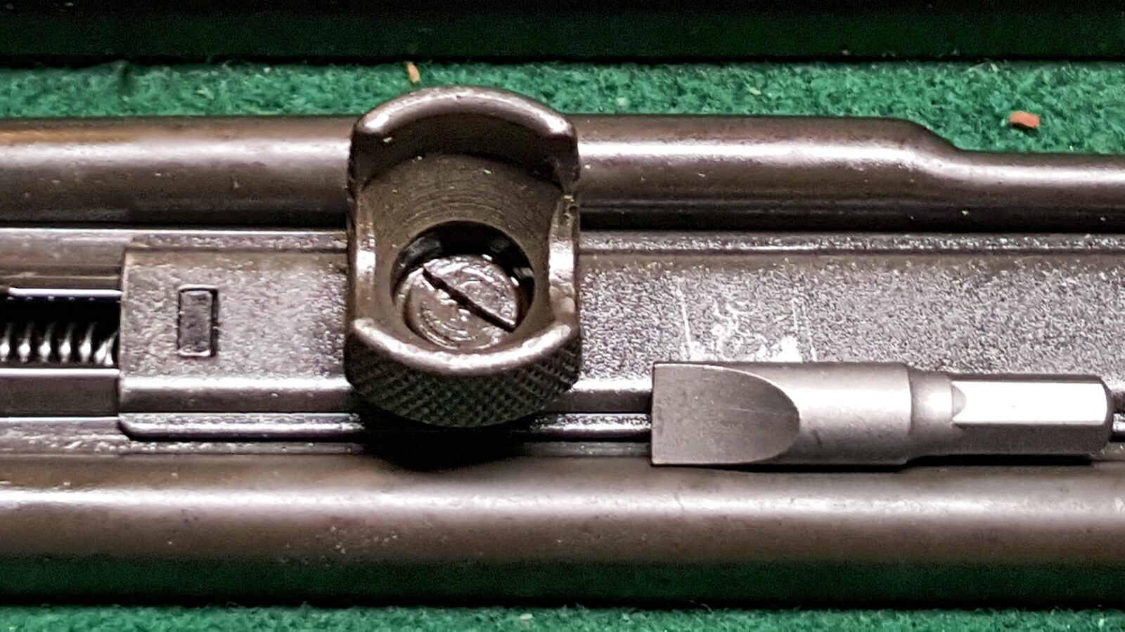
1] The first step is to select a hollow ground screw driver bit that fills the slotted screw located in the middle of the cocking handle and remove it. Note, my screw had what looked like white thread locker on it. It did come off with firm pressure so it’s critical you use a properly sized bit. I have a big Weaver screwdriver set for just this reason that I use all the time when I am working on firearms.
In the photo below, I show the cover partially ratcheted back. Release the tension on the spring by pulling the handle all the way to the rear and allow it to travel all the way forward.
2] With the screw removed, the cocking handle lifts right off the top cover slot plate located under it. The cocking handle lug will simply drop down out of the slot. In the next photo you can see the top components but not the lug for that reason. You can also see the thread locker remnants in the cocking handle screw.
3] Turn the cover upside down over the table surface and the coking lug assembly will be dangling from the cocking handle return spring that is connected both to it and top cover. You can simply lift the pawl out of the lug.
4] It is now just a matter of reassembly and it takes two hands so my photos are limited 🙂 Put the cocking lug back into the slot from the bottom side of the top cover. Then turn it over while holding the lug in place and stack the top cover slot plate on it so the elevated tabs on the lug marry up with the slots in the top cover slot plate. While wishing for a third hand, put the cocking lever and screw into position and screw them into place. Note, I would recommend some form of medium Loc-tite/thread locker to keep the screw from coming loose.
5] On my dust cover, I did bevel the rear of the cover just a bit to encourage the top cover catch to engage. My cover is nice and tight and I want it that way so I did not trim anything else. In the next photo you can see my cover in black with the right angled top sanded down just a bit compared to the bottom original.
That’s all there is to it and I hope this helps you out.
At first glance, the Uzi grip frame is intimidating! There are springs, pins and levers all over the place but it turns out to be surprisingly simple. Now, I need to tell you something – I read everything I could on the grip frame [Notably the excellent UziTalk post about assembling the frame, Beaker’s great Uzi build write up on NES and Gaboury’s Uzi book] and I kept the spare Uzi’s grip frame fully assembled sitting on the bench for reference. As you follow the steps, it becomes pretty straight forward actually.
Legal Disclaimer: I am not a firearms attorney nor do I claim any regulatory expertise and you accept all responsibilities and liabilities for compliance with all federal and local laws that pertain to you. I sorted out posts on what is required to make the Uzi legal in terms of the grip assembly and it seems to come down to two elements: 1] Mike at NDS received guidance on the McKay receiver that there needed to be a blocking bar for the bolt and the selector lever in the grip frame must be blocked from going to the full auto position [See post #7] 2] The sear needs to either modified for for semi-auto use or replaced with a dedicated semi-auto unit to fully penetrate into the semi-auto receiver. A full auto sear will not fit in the McKay receiver’s holes and I am using a McKay to be clear.
Before you get started, you need to make a quick tool. Take any small blade screw driver and use a Dremel fiber reinforced cut off wheel to make a notch in it. Literally, just cut straight in. You will need this to push down the surprisingly stout legs on the trigger spring that have to pass under some hooks and then under the disconnector.
1] Remove the two screws that hold the grip panels in place. You’ll notice the grip panels are beat up but the parkerized finish and parts are in exceptional shape. All my internals looked like new. I am real pleased with the kits Robert RTG sent me.
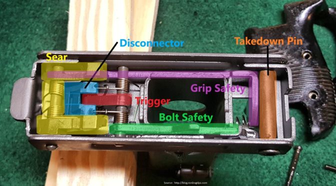
2] Here’s our first peek inside the grip frame. This crazy looking thing is actually very straight forward. I was really impressed by how they did the pins – the look like screws but you actually insert the pins and turn them into position to lock everything in place. It’s really a very well thought out way to do it.
I will never get any awards for illustration but here are the major parts labelled so you can see them. Note how the trigger pin bends forward, under the hooks and under each side of the disconnector. To remove and install the trigger requires the notched screw driver I showed above as the notch makes moving each incredibly stiff small spring leg on the trigger way, way easier.
3] Next, I pushed out the takedown pin. It just presses right out like an HK’s. I suspect that whomever demilled the kits just stuck it in there for safe keeping. Have baggies or a parts tray to keep track of all of this. I always recommend taking photos and/or making notes too.
4] Before you remove the sear, look at how much room you have in front and under the sear. This will aid you when you weld in the selector stop plate later. I used a small screw driver to push out the sear pin. The spring is attached to the sear and when the pin is removed, it comes out as a unit. This unit will either need to have the lobes cut down to fit in the receiver or use a new dedicated US semi-auto sear but you will use the same spring so be sure to save it.
5] Next, use your tool to push down on the trigger spring legs such that they are sticking up in the air and not under the disconnector or the wire hooks.
6] Once the trigger pin is removed you can then remove all the other parts. Remove the grip safety spring and then lift the grip safety straight out of the frame.
7] Next you need to size the selector stop plate you need. In digging around, I could not find any sheet metal between .050-.075″ thick in my collection so I simply bought a pre-made selector stop plate from US Barrel Shrouds for $2.95 and made sure the selector stopped appropriately and where to place it for welding before I removed the selector bar spring and the selector bar. You want to make sure the selector fully stops on semi-auto, the middle setting, and not further to the left. You may need to adjust the plate a bit – in my case it dropped right in and worked. Also, the selector bar has virtually no vertical travel when the grip frame is fully assembled so don’t worry about that right now.
Note, the selector knob is just pressed onto the selector bar. When you remove the bar, the knob will fall off so be prepared to catch it.
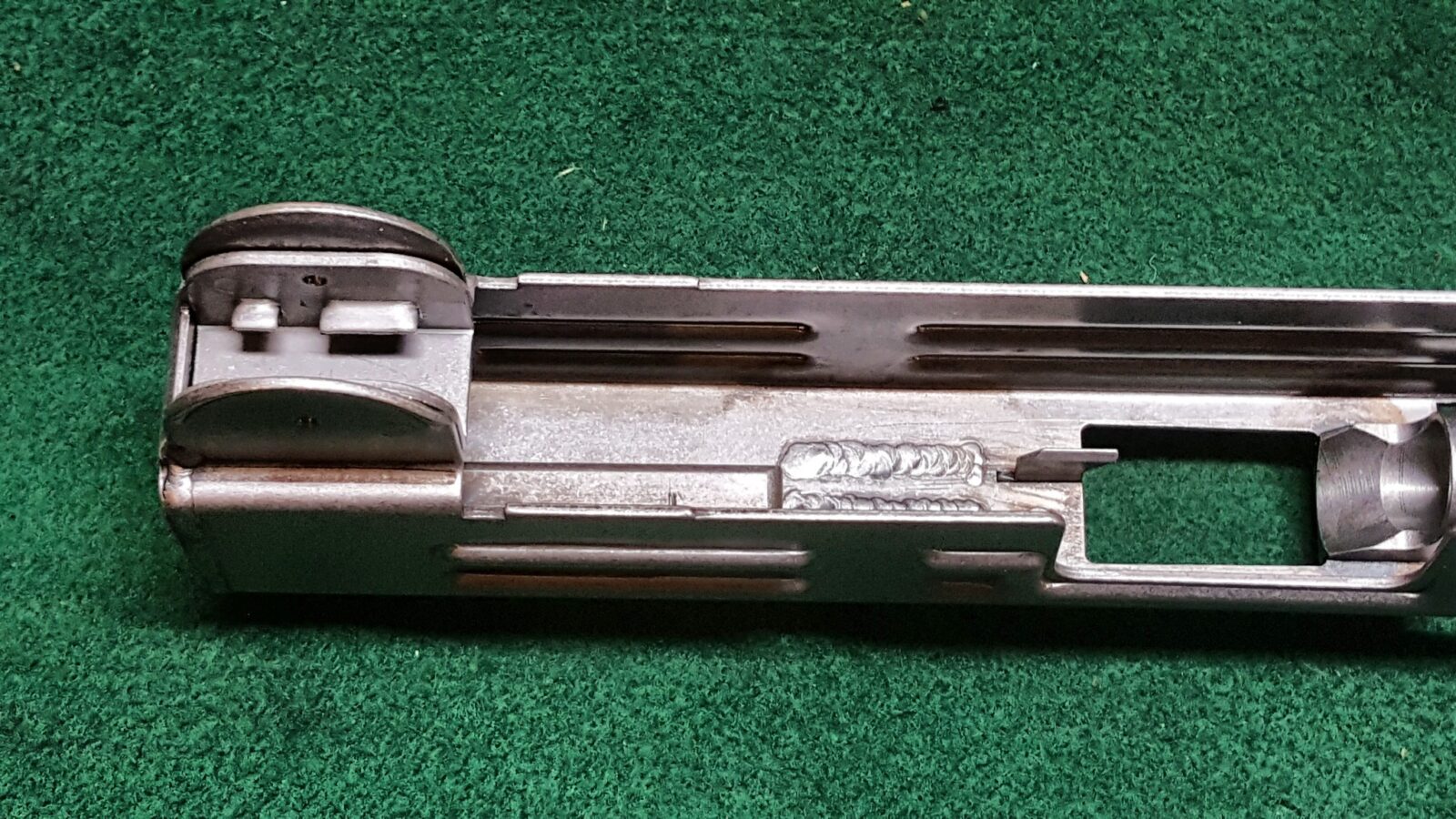
8] I then degreased and sanded the frame to remove the parkerizing in order to get a good weld. I then clamped the work and spot welded it with my MIG. You actually have a fair amount of room so the weld does not need to be perfectly flat – I did a bit more sanding than I needed to before I realized the amount of room I had to work with during test fitting. I also did two small spot welds in each corner by the lop of the frame just to be sure. My stop plate is rock solid now.
9] I did not bother removing the magazine catch and at this point, I stopped as I collected all my parts to refinish them with Molyresin. I them re-assembled following that.
10] To re-assemble the grip frame, what saved my bacon was the excellent guidance from Uzi Talk with one exception. The McKay receiver does not use a bolt safety so when the Uzi Talk directions mention it, remember that you are not going to install the bolt safety. If you do mistakenly install the bolt safety, the grip frame will not fit onto the receiver.
During assembly, I put Tetra grease on everything to help everything slide plus I oiled the rotating parts on the pins. There is an old saying “if it slides, grease it. If it rotates, oil it.”
Also, I mentioned I used a US made semi-auto sear. I bought mine from US Barrel shrouds and it worked great. The original is on the left with the spring still attached. The new one is labelled US in the photos below or does not have the spring yet. I thought you might want to get a good look at it for reference. Note how the “pads” at the rear of the semi-auto sear are shorter but there is still a shelf at the bottom.
Below is a photo of the FCG group with the sear spring moved over plus it’s interesting to see the two fire control pins – the shorter one with the flat end is the trigger pin and the longer one is for the sear.
Uziel Gal considered a number of different stock designs until they settled on the final design in December 1950 and did the first production run in 1951. The wood stock evolved as they corrected breakage issues and you will see stocks with different profiles over the years. Purely FYI, The steel folding stock was added in 1956 due to Israeli paratroopers requesting a shorter weapon.
Legal Disclaimer – I tried to sort through how to permanently attach the wood stock to avoid creating a SBR. There aren’t any ATF letters specific to this method. My approach is based on a method documented on Uzi Talk and that approach has not been legally questioned since the forum posted it – click here to read their guidance. You will need to decide if this approach is acceptable to you. I am not a firearms attorney nor do I claim any regulatory expertise and you accept all responsibilities and liabilities for compliance with all federal and local laws that pertain to you.
The problem is that if you remove a quick detach stock from an Uzi with a 16″ barrel, then it falls under 26″ then it is a short barreled rifle (SBR). Thus, the Uzi’s wood stock must be permanently attached. Let me point out there is a ton of fear, uncertainty and doubt (FUD) in terms of the converting the quick detach wood stock to be considered permanently attached. The consensus of cooler heads seems to be that if you attach the stock to the Uzi such that it can only be removed with tools, then it is considered permanently attached by the ATF. If you think about it, most shotguns and rifles would be too short if their stocks were removed for maintenance and they all require tools to have their stocks removed and, thus, are no longer “quick”. The Uzi wood stock bracket is modified by having the rear receiver attachment point ground down and connected via a blind screw that can’t be accessed without first removing three external screws and pulling the wood stock off. Most of my long arms have the stock secured by one screw that may or may not be exposed. For example, a shotgun’s stock screw is typically located under the recoil pad. Many rifles have one or two exposed screws under the action. In short, the Uzi’s stock is now permanently attached following the same logic. This is a well trod path as many individuals have posted write ups and videos about the conversion plus JJ Custom actually sells brackets that have already been converted.
Preparing the wood stock for the Uzi may take you a bit depending on repairs and the finish you choose to use. I looked at the stocks in both of my Uzi kits and the first one was in the best shape so that is the one I used.
There are a number of things that must be done at this point. To reach the minimum 26″ overall length requirement, the stock must be permanently attached so I’ll talk about what I did for that plus the stock needed to be stripped, the gouges fixed and the wood refinished.
In my first kit, the screws were all in very good shape. In the second kit they were chewed up. I can’t stress this enough – use bits that fit the entire screw – this means both the length and width of the blade edge. By full supporting the slot, you can turn quite a bit. If you have an ill-fitting bit then you will tear up the metal. Here is the Weaver set that I use all the time – I may use the included screwdriver handle or put the bit in my Dewalt screwdriver to save my wrist – it just depends on what I am doing:
1] Remove the screws that attach the stock mounting bracket to the stock. You can see the big one at the rear and then the two screws towards the front. I used a big bit to get each screw moving – that is why they came out without damage. By the way, you can see how the old quick detach method worked – the front of the bracket slid into the grip lug, the pressure plate between the screws supplied tension with the rear cylindrical receiver attachment point slid into the receiver. The lower catch just locked the assembly in place. It was an elegant design really but one we need to eliminate.
Here’s what the bracket looks like. By the way, you can see one of the big blade bits in my DeWalt power screwdriver. The quick release lever engages or releases the notch in the receiver and the cylinder pushes into the receiver to lock it in place. We’ll come back to the in a minute.
2] The next step is to strip the wood. Use your favorite wood stripper, such as BIX, or brake cleaner to get rid of the tons of oil that is in the wood. I used a ton of brake cleaner as it was snowing outside and I just wanted to get it done 🙂 If it were warm weather, I would have used Bix 2-3 times to get all the crud out.
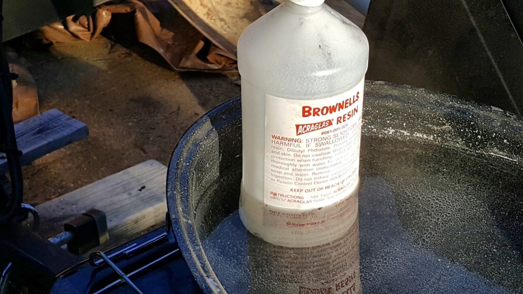
3] I then mixed up a batch of Brownells Acra-Glas liquid epoxy, added black dye and glass fibers and then filled in all the gouges. The epoxy then sat overnight and cured. In cold weather, make sure you do something to keep the epoxy warm so it will cure properly. (Click here if you want tips on how to work with epoxy). Also, I added links to it at the end of this post.
Note, you can barely see two hairline cracks in the front of the stock to the left and right of the bracket. They were repaired with quality thin viscosity super glue — I like the Bob Smith brand personally and use his different formulations all the time. This stuff is very thin and readily runs into cracks. I just push the crack open, pour in the glue and then clamp the work for a minute while it cures.
4] I then sanded the stock down starting with 100, 150, 220 and finally 400 grit sandpaper to get it smooth. I purposefully used black so they would look like repairs or burns. I figured this Uzi was older than me and ought to have some character marks to remind people of its age.
5] I rather liked the color of the wood in the parts kit so I used a 50/50 combination of boiled linseed oil (BLO) and black pine tar. Now this old school blend actually protects the wood and gives it a really nice slightly darker matte finish bringing out the color of the wood. So you can see we went from a yellowish color above to warmer orange-ish brown below. You apply the finish using a foam brush and chase it into the wood using a heat gun. Literally this stuff should be bubbling from the heat. You then wipe it down with a clean rag and repeat until you get the finish you want. I then go over with 0000 steel wool to make sure it is nice and smooth.
Note, properly dispose of BLO soaked rags as they may spontaneously combust from the heat of drying. The proper method is to lay them flat on a noncombustive surface and let them dry thoroughly. The length of time depends on many factors. I burn mine. Never ever just throw them in the trash.
6] Next up we need to convert the stock bracket to be permanently attached – meaning it must screw into the receiver. I have seen several methods used and I’ll share with you what I did and you can decide how you wish to proceed. If you are uncomfortable with the machining required, a firm known as “JJ Custom” sells the brackets already converted.
6.1] This is what the quick detach stock bracket looks like in the first picture and the cylindrical protrusion normally slides into the circular hole in the end of the receiver shown in the second photo.
6.2] What we are going to do is to sand the cylinder almost completely away so it just barely goes into the hole to locate/position the assemby. Before that, I would recommend removing the catch from the bottom by pressing out the pin and removing the assembly. Be careful with the spring – mine launched into orbit and I never found it so I used a second one off my spare kit. Note, you can’t order this spring – you have to buy either an entire stock assembly or just the bracket if you can find it. I bought a third stock assembly and the moral of this story is to carefully catch that little spring vs. letting it launch. Note, the next photo shows it after I drilled and sprayed Molyresin on the part but I wanted to share a close up of the sanded down cylinder. I have a big 2×72 grinder (sander) that I use for knives that makes this work very quick. Just take your time and sand it square.
6.3] Next I took a folding stock mounting nut and ground it down until it just barely fit in the receiver hole from the inside. This nut is tapped for a 1/4-20 screw so this made sense to me. I carefully center punched the middle of the cylinder and drilled it with 9/32″ bit to give a bit of wiggle room to line up with the mounting nut. Again, the photos are after finishing. I went this route as the bolt buffer has a channel at the bottom that allows room for this nut and the dimensions had already been sorted out. I bought the folding stock nut from Robert RTG.
6.4] I have a lot of 1/4×20 button head screws so used one of them to attach the bracket and then drilled a recess in the stock to allow it to fit. I simply stuck the stock on the bracket and marked where to drill a 1/2″ recess. The intent is that the bracket can’t be removed without first removing the stock. A 1/4″ alloy bolt can handle a lot of sheer stress as can the thick receiver – that bracket is no longer quick anything. Also, it took a lot of filing and fitting to the the front of the stock bracket to slide under the grip frame lug on the receiver and I intentionally left the fit very tight to avoid slop. This was just a test fitting as I still needed to do the front screws on the stock.
6.5] In looking at the stock and bracket, I decided to countersink the wood from the bottom and insert screws from the bottom. This is not a traditional look but I don’t think it messed the lines up too bad. The one point I did pause and think about was limited material to thread into on the bracket. Because the Israelis recessed the screw head holes, I had about an 1/8″ of material to thread so I debated welding the holes closed and then drilling and tapping new ones. I decided to skip welding for now and give it a go with bigger 1/4×28 NF flat head screws that I turned down the heads by chucking them in a hand drill and pressing the spinning screw head against my spinning sander. This trick works great by the way. I used a 1/2″ counter sink and a 9/32″ bit to open up the two stock holes. The holes in the bracket were opened up with a #3 cobalt bit and tapped with a quality 1/4-28 tap with cutting oil.
The second photo below shows the front hole opened up and then I did the same to the second one. The result seems very solid and I can always go back and weld the holes shut and start over if I have problems though I doubt I will. A 9mm doesn’t have much recoil, the Uzi is actually pretty hefty and the inertia will soak up the recoil plus I will be shooting this as a semi-automatic. I do not expect a ton of stress on those two screws and big top wood screw and recessed tang pushing into the surrounding wood will bear the brunt of it.
I then inserted the screws, tightened them down and used the sander to make them flush with the bracket. I then disassembled it so I could apply the Molyresin finish later.
6.6] The stock was ready to go other than one minor detail – the sling swivel was a bit bent so I installed the brass protector plates on my vise’s jaws and then tightened them down on the wire loop to straighten it out.
So at this point, the stock was done. I had it in pieces waiting to apply the Molyresin finish that I will cover in post six.
It’s a bit out of sequence but for folks just reading this post about the stock, here is the end result. With the new permanently attached stock, the overall length is a safe 31″. Here are some up close photos of the finished product so you can see how it turned out:
Now there are parts you need from the kit to do your assembly so let’s step through them. I would highly recommend that you have a means to organize your parts and not lose them. Zip-Loc bags, parts tray, etc.
Also, another fellow did a great write up on his disassembly – click here to read it.
1] Remove the handguards – they are held in place by two slotted screws. I highly recommend you always use gunsmith/hollow ground screw driver bits that fill the whole slot of a screw to avoid tearing the screws up. These screws are not under much torque and mine very readily came out. You may want to replace these with new handguards. Mine were in tough shape due to being bounced around in the parts kit bag.
2] You will need the front sight assembly. It is comprised of the inner sight itself, a locking nut and a washer underneath. A real Model A Uzi front sight tool makes a world of difference as you can easily loosen the locking nut and then unscrew the whole assembly.
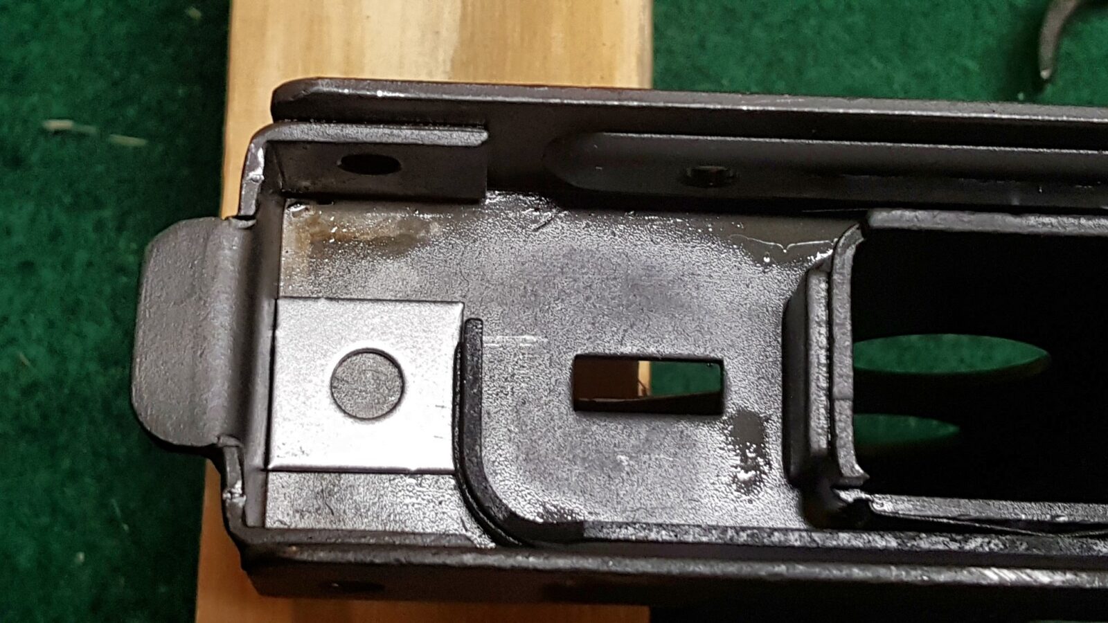
3] Remove the barrel nut catch assembly. It is comprised of the catch itself and a spring. Reach in from the rear under the sight, push the tab down with your finger and pull the assembly out. You can do this with your fingers. If you look at the first photo in step one, you can see the catch still in the old receiver stub – it is the L-shaped protrusion over the threads. You’ll notice the new receiver (which is still in the white in these photos) does not have it. Now, in the second photo, if you look at the old stub on the right you will see the tab of the catch sticking out – this is what you push down with your finger while pulling out of the front.
4] You will need to salvage the front sling swivel. I sanded mine down flat, center punched the middle of the rivet, start with a small 1/8″ drill bit and worked my way through larger and larger bits until the swivel separated from the old rivet. I then used a punch and removed the remnants of the old rivet from the center of the swivel. By the way, I’ll tap the sling and mount it with a button head screw and Loc-Tite in a later post. Don’t worry about tracking down a replacement rivet and squishing it unless you really want to.
5] Remove the rear flip sight assembly. Now, there is a slotted screw on one side and a tiny nut on the other. Be careful when you loosen the nut as it will come right off. I used a long punch to push the screw back far enough to then grab the screw and pull it out.
6] The next step removes the top cover catch. The rear sight spring actually covers the catch assembly so just pry the spring upward and you will see the top catch and the captive spring. Now be careful – this spring will launch if it slides over the rear lip so carefully remove the top catch itself by sliding it out the front.
7] You will need the barrel nut. Mine was in a small bag in the parts kit.
8] You need the top cover. Now I bought a modified one with a picatinny rail attached. If you use the original cover, there is a small wedge called the “cocking pawl” that you will need to remove. My cover was lose in the bag so I just set it to the side.
9] You will need the return spring assembly but you will need to cut the buffer plate off at the end of the guide rod. I just took a pair of diagonal wire cutters, made one snip from the side and it literally came right off the return spring guide rod. Be careful not to bend the guide rod – you will use this spring assembly with the new bolt.
10] You need two things from the submachine gun open bolt. Put the bolt on a bench block and push/tap out the extractor retaining pin from the side of the bolt – tap/push on the small side with a punch. The extractor looks like a screw from the rear end of the bolt but it actually presses right out. Push from the end with a punch or small screw driver and it will push right out the front of the bolt face. Note, the slot is so you can use a screw driver to rotate the extractor into proper position when you install it.
11] In my parts kit, the entire grip frame assembly was in the bag. Now there are some critical changes that must be made to it but for now, set it to the side. The grip panels were chewed up so I bought a new set of those along with handguard panels.
12] You need the complete wood buttstock assembly with the entire wood stock mounting bracket system and all the hardware on the stock.
That’s it for now. The next blog post will get into the details of how to refinish the wood stock plus permanently attach it.
One of the firearms that had an impact on me growing up was the iconic Israeli Uzi. In the 1980s you would see them in the news, TV shows and movies all the time. Today, being quite a bit older, what interests me is the history and engineering that led up to this weapon. Suffice it to say that Israel has known conflict even before the country was founded in May 1948 and certainly ever since. Israel first fielded the Uzi in
I’m not going to duplicate the history as there are some excellent resources out there that explain the political climate and how the Uzi came into being.
The Uzi has evolved into a variety of weapons including the micro uzi, semi-auto versions and so forth. What interested me was the full size Uzi that I had grown up hearing so much about and you’d see them with the original wood stock and the metal folding stock.
Over the years, I’ve made many AKs and ARs for personal use. I’ve been really busy but wanted to build something different. For the past several years I have noticed that there are a ton of Uzi kits for sale from the various parts kits vendors and this sparked my interest. For me, part of the challenge of building from a kit is learning how to do so legally and finding all the parts.
I knew I wanted to build a carbine vs. a pistol so that shifted me in the direction of a wood stock for a number of reasons:
To be classified as a rifle, the barrel needed to be at least 16″ with an overall length of 26″.
To get the overall length, that meant I either needed an even longer barrel or a permanently attached stock that would surpass that 26″ minimum.
The resulting carbine would be front end heavy and the wood stock would help balance things out.
I am not a huge fan of my cheek being on sheet metal – I prefer wood with a gently bend.
Now you many have a different perspective and that is just fine but due to this I ordered two wood stocked Uzi kits from Robert RTG. I only planned to build one Uzi but purchased a spare kit for donor parts just in case. What arrived were two seriously oiled kits. The wood was a tad beat up as were the pistol grip and handguard panels – probably from being packed with the parts. The bolt and fire control group honestly looked like new.
In terms of the receiver, all my research pointed me to buying one from McKay. They offer just the bent receiver shell and you can do all the welding or a fully welded receiver that is all set for semi-auto use and ready for you to assemble with. I opted for the ready-to-go model and based on McKay’s reputation, I also ordered my 16″ 1:10 twist 9mm NATO chambered barrel from them also. I placed my order direct with McKay, had them ship it to my FFL, Scott Igert, and it arrived a week later.
McKay really did a real nice job on the receiver. Here it is with some of the original stubs sitting by it:
Here are the details that McKay took care of when they make their fully welded receiver:
The front trunnion has a reduced inner diameter to prevent installation of a military model
The rear barrel support ring must not allow a military barrel to be installed
The bottom of the semi-auto feed ramp will block a full auto sear – in other words, it is just a tad too long for the full length original sear to fit.
The right side of receiver behind the ejection port has a block bar welded in place that prevents the installation of an original full auto open bolt.
The other plus is that everything above is American made so that means the receiver and the front trunnion count as US-made parts. By the way, in terms of 922r, an Uzi has 13 parts on the 922r parts list so that means three must be replaced with US parts to meet the maximum limit of 10 foreign parts. The McKay receiver, front trunnion and US-made barrel will enable you to meet the parts count requirement.
By the way, there are a lot of other posts about how to do an Uzi:
At any rate, let’s wrap this post up and will discuss the the parts you will want to remove from the old kit.
Note, I have to buy all of my parts – nothing here was paid for by sponsors, etc. I do make a small amount if you click on an ad and buy something but that is it. You’re getting my real opinion on stuff.