Executive Summary
The evolution of Extreme Long Range (ELR) precision fire and the deployment of advanced anti-materiel and sniper weapon systems have pushed small arms ballistics into operational envelopes previously reserved for artillery fire direction centers and aerospace engineering teams. Platforms chambered in .338 Lapua Magnum, .338 Norma Magnum, and emerging large-capacity wildcats like the .338 EnABELR are routinely tasked with engaging high-value targets at distances extending well beyond 1,500 meters. At these extreme ranges, the projectile’s time of flight mandates an unavoidable and dramatic deceleration through the local sound barrier, transitioning from a highly stable supersonic regime to a fundamentally different subsonic one. This phase, universally known as the transonic flight regime, typically defined as spanning from approximately Mach 1.2 down to Mach 0.8, represents the most volatile, unpredictable, and chaotic aerodynamic environment a spin-stabilized projectile can experience during its free-flight trajectory.
The primary objective of this engineering white paper is to exhaustively analyze the physical mechanics of transonic aerodynamic destabilization in heavy-for-caliber .338 projectiles, specifically focusing on the 300-grain class of long-range tactical bullets. As a projectile decelerates through this critical transonic window, the supersonic shockwaves that were firmly attached to the nose (meplat) and bearing surface begin to detach, fluctuate, and migrate along the body of the bullet. This breakdown of the supersonic flow field initiates a highly complex series of cascading aerodynamic consequences. Most notably, it causes a severe disruption in the spatial relationship between the projectile’s physical Center of Gravity (CG) and its aerodynamic Center of Pressure (CP). While classical simplified ballistics often emphasizes a generalized forward shift of the longitudinal center of pressure during deceleration, advanced computational fluid dynamics (CFD) and active Doppler radar telemetry reveal highly complex, localized rearward shifts in pressure centers, particularly those associated with unsteady wake shedding and Magnus moments.
Coupled with the phenomenon of shock-induced boundary layer separation—a localized turbulence generation mechanism that leads directly to the physical hammering known as Mach buffet—these migrating pressure centers introduce immense overturning torques that aggressively test the mathematical limits of the projectile’s gyroscopic and dynamic stability. If the bullet’s physical design, mass distribution, and imparted spin decay cannot successfully damp these oscillating lateral forces, the projectile enters a state of limit cycle yaw. In this state, it suffers catastrophic, non-linear losses in its ballistic coefficient (BC) and deviates entirely from its predicted ballistic trajectory. By examining the six-degree-of-freedom (6-DOF) physics models, analyzing empirical drag coefficient (Cd) migration data, and applying mathematical dynamic stability formulas in plain text, this report provides defense procurement officers, aerospace engineers, law enforcement armorers, and Tier-1 competitors with the fundamental aerodynamic insights necessary to optimize .338 caliber weapon systems for reliable, repeatable trans-barrier flight.
1.0 Introduction to Extreme Long Range Ballistics and the .338 Caliber Envelope
1.1 The Operational Demands on the .338 Magnum Class
The modern battlespace and highly competitive ELR shooting environments require weapon systems capable of delivering high-kinetic-energy payloads with extreme first-round impact probabilities at ranges that frequently extend beyond one terrestrial mile. Historically, this capability was strictly the domain of heavy, crew-served weapons or large anti-materiel rifles chambered in .50 BMG (12.7x99mm NATO). However, the extreme weight, immense recoil signature, and logistical footprint of the .50 BMG make it suboptimal for highly mobile sniper teams and precision tactical units. Consequently, the .338 caliber (8.59mm to 8.61mm) has emerged as the premier intermediate solution, bridging the critical capability gap between standard medium machine gun cartridges (such as the 7.62x51mm NATO or .300 Winchester Magnum) and the heavy anti-materiel rounds.1
Cartridges such as the globally recognized .338 Lapua Magnum, the .338 Norma Magnum (selected by United States Special Operations Command for the Advanced Sniper Rifle program), and newly engineered proprietary wildcats like the .338 EnABELR (Engineered by Applied Ballistics for Extreme Long Range) achieve this extended reach by launching exceptionally heavy-for-caliber, highly aerodynamic projectiles.2 These projectiles, typically weighing between 250 and 300 grains, are propelled at initial muzzle velocities ranging from 2,700 to over 2,900 feet per second, depending on the propellant charge and barrel length.1
The defining characteristic of these heavy-for-caliber .338 projectiles is their exceptionally high Sectional Density (SD) and their extraordinarily high Ballistic Coefficients (BCs). For example, the 300-grain Berger Hybrid Open Tip Match (OTM) Tactical bullet boasts a G1 BC of 0.818 and a G7 BC of 0.418 to 0.421, indicating a superior geometric ability to overcome atmospheric drag, retain kinetic energy, and resist lateral crosswind deflection over extended flight times.1 However, regardless of the launch velocity or the aerodynamic efficiency of the bullet’s ogive, atmospheric drag is an omnipresent, retarding force. At an extended distance, typically between 1,200 and 1,600 meters depending on the specific muzzle velocity, bullet design, and ambient air density, the .338 projectile will inevitably shed enough velocity to approach the speed of sound.1
1.2 Defining the Transonic Flight Regime
In the fields of aerospace engineering and advanced exterior ballistics, flight regimes are categorically defined by the Mach number, denoted as ‘M’. The Mach number is the dimensionless ratio of the projectile’s relative velocity to the local speed of sound in the surrounding fluid medium (in this case, atmospheric air). Supersonic flight occurs when the Mach number is safely greater than 1.2, a state where the vast majority of the airflow over the entire surface of the projectile is moving faster than the local speed of sound. Conversely, subsonic flight occurs when the Mach number is less than 0.8, where all airflow over the projectile, from nose to base, is strictly slower than the speed of sound.
The transonic regime is the highly critical, transitional boundary spanning the velocity range roughly from Mach 1.2 down to Mach 0.8.4 It is fundamentally characterized by mixed or chaotic flow. Depending on the highly specific local geometry of the projectile, some regions of the air flowing over the bullet are supersonic, while adjacent regions are subsonic.4 As the .338 bullet slows to approximately 1,340 feet per second (which equates to Mach 1.2 at standard sea level atmospheric conditions), it enters this chaotic zone.6 The shockwaves that were firmly attached to the projectile’s nose and bearing surface during the stable supersonic flight phase begin to shift, detach, interact, and reflect.7 This mixed-flow aerodynamic environment produces violent chaos, generating severe mathematical nonlinearities in axial drag, lateral lift, and overturning pitching moments. For a spin-stabilized rifle bullet, successfully navigating this regime without tumbling, yawing excessively, or deviating from the parabolic trajectory is the ultimate test of its aerodynamic design and inherent gyroscopic rigidity.8
2.0 Foundational Aerodynamic Forces in 6-Degree-of-Freedom Flight
To rigorously understand exactly how a bullet destabilizes in the transonic zone, it is absolutely imperative to first define the myriad forces acting upon it within a six-degree-of-freedom (6-DOF) analytical framework. A long-range projectile in free flight is not merely a theoretical point mass traveling along a simple, two-dimensional parabolic arc; it is a complex rigid body experiencing continuous translation in three spatial axes (longitudinal X, lateral Y, and vertical Z) and simultaneous rotation about three angular axes (pitch, yaw, and roll).10
2.1 Primary Aerodynamic Forces
When a .338 caliber projectile exits the muzzle of a rifle, it is immediately subjected to the downward acceleration of gravity and a highly complex, interacting matrix of aerodynamic forces and moments. The primary linear forces include:
- Axial Drag Force: This is the primary retarding force operating directly parallel and opposite to the projectile’s velocity vector, constantly robbing the bullet of its forward kinetic energy.11 Drag is a composite force made up of wave drag (shockwave generation), skin friction drag (viscous air resistance), and base drag (low pressure acting on the rear of the bullet).
- Lift Force (Normal Force): This is the force acting perpendicular to the velocity vector. Unlike an aircraft wing, a perfectly symmetrical bullet flying perfectly straight at zero degrees Angle of Attack (AoA) generates zero net lift. However, gravity inherently causes the trajectory to curve downward, forcing the bullet to present a microscopic Angle of Attack to the relative wind. This AoA induces a measurable normal force.12
- Magnus Force: A lateral force generated by the direct interaction of the bullet’s rapid axial spin and the cross-flowing air when the bullet is at an angle of attack. The spin accelerates the air on one side of the bullet while decelerating it on the other, causing a pressure differential that pushes the bullet sideways, independent of actual wind drift.11
2.2 Aerodynamic Moments and Torques
Corresponding directly to these linear forces are specific aerodynamic moments (torques) that attempt to continuously rotate the bullet around its internal Center of Gravity (CG):
- Overturning Moment (Pitching Moment): Because the theoretical Center of Pressure (CP) is almost always located ahead of the Center of Gravity on modern spitzer bullets, any angle of attack generates a normal force that acts as a physical lever, attempting to forcefully flip the bullet end-over-end backward.11
- Pitch Damping Moment: A highly critical restorative moment generated by the fluid medium physically resisting the angular velocity of the bullet’s continuous pitching and yawing motions. This is the primary mechanism that suppresses wobble and allows the bullet to “go to sleep”.14
- Magnus Moment: The torque generated by the lateral Magnus force. Depending on the exact longitudinal location of the Magnus force relative to the CG, this moment can either help stabilize or severely destabilize the projectile’s epicyclic coning motion.14
- Spin Damping Moment: The friction-induced torque that gradually slows the projectile’s axial rotation (RPM) as it travels downrange.14
2.3 The Center of Gravity versus The Center of Pressure
The fundamental, inherent mechanical challenge of any conventional small arms projectile is that it is statically unstable by design. The Center of Gravity (CG) is the singular internal point where the bullet’s physical mass is perfectly balanced.12 In heavy .338 projectiles, which feature dense solid copper jackets encompassing heavy lead alloy cores (or monolithic machined copper/brass construction), the mass is biased toward the rear. Consequently, the CG is typically located near the rear-middle of the projectile’s overall length.17
Conversely, the Center of Pressure (CP) is the theoretical spatial point where the sum total of all aerodynamic pressure fields (both lift and drag) acts upon the external body.18 Because of the elongated, highly pointed shape (the ogive) of a modern low-drag bullet designed to pierce the air, the highest aerodynamic static pressures are concentrated heavily near the nose section. Consequently, the overall Center of Pressure is located significantly ahead of the Center of Gravity.11
When the bullet experiences any external disturbance in flight,such as a crosswind gust, muzzle blast turbulence, or transonic shockwave reflection, it immediately develops an Angle of Attack. Because the CP is located forward of the CG, the oncoming relative wind exerts a powerful force at the CP that acts precisely like a lever, trying to force the bullet’s nose further away from the intended flight path. This dynamic is the overturning moment.12 To prevent the bullet from tumbling instantly end-over-end upon exiting the muzzle, the barrel’s rifling imparts a violent axial spin (often exceeding 200,000 to 250,000 Revolutions Per Minute). This spin creates immense gyroscopic rigidity that translates the destructive overturning moment into a circular precession and nutation, keeping the bullet generally pointed forward.19
3.0 The Mechanics of Center of Pressure Shift in Transonic Flight
3.1 Supersonic versus Subsonic Flow Field Topography
During high supersonic flight (for example, at velocities around Mach 2.5), the aerodynamic flow field surrounding the .338 projectile is dominated by a strong, firmly attached bow shockwave at the extreme meplat (tip) of the bullet, followed by expansion fans along the curvature of the ogive. In this regime, the pressure distribution across the bullet’s jacket is highly predictable, and the aerodynamic Center of Pressure remains relatively static in a stable forward position. The exceptionally high velocity ensures that the dynamic pressure is immense, but the gyroscopic stability (Sg) imparted at the muzzle is mathematically sufficient to overcome the calculated overturning torque.
As the projectile decelerates into the upper bounds of the transonic regime (approaching Mach 1.2), the fundamental physics of the flow field undergo a radical and volatile transformation. The speed of the air flowing over the bullet’s surface is no longer uniformly supersonic. The local velocity over the thickest, widest part of the bullet (the bearing surface) may still be significantly supersonic, while the flow near the tapering boat-tail or the extreme nose may drop to subsonic speeds simultaneously.4
3.2 The Deceleration Paradigm and Primary CP Migration
There is a complex and frequently misunderstood dynamic regarding the exact longitudinal movement of the Center of Pressure during transonic transitions. In traditional aircraft design and aerospace engineering, accelerating a vehicle from subsonic to supersonic speeds typically results in a pronounced rearward shift of the primary aerodynamic center, a dangerous phenomenon known historically as “Mach tuck” which forces the aircraft’s nose downward.5
Conversely, for a free-flight projectile decelerating from supersonic velocities down to subsonic speeds, the primary longitudinal Center of Pressure actually shifts forward.6 As the .338 bullet slows below the Mach 1.2 threshold, the normal shockwave that was previously situated aft on the bullet body begins to physically migrate forward toward the ogive. This forward migration of the strong shockwave significantly increases the localized static pressure directly near the nose of the projectile. Because the highest pressure concentration is moving forward, the overall integrated aerodynamic Center of Pressure shifts further forward, moving further away from the Center of Gravity.6
This specific forward shift of the primary CP has a catastrophic multiplying effect on projectile stability: it directly increases the physical distance (the moment arm) between the Center of Pressure and the Center of Gravity. By the fundamental laws of classical mechanics, Torque equals Force multiplied by Distance. Even if the overall dynamic pressure (and thus the raw total lift force) is decreasing due to the lower overall velocity, the lengthening of the moment arm causes the overturning pitching moment coefficient (Cma) to spike dramatically relative to the gyroscopic rigidity of the bullet. The bullet suddenly experiences a much greater physical leverage attempting to flip it backward exactly when it is entering a chaotic aerodynamic environment.6
3.3 Analyzing the Secondary “Rearward Shift” Phenomenon and Magnus Moment Reversal
While the primary normal force CP shifts forward during deceleration, advanced 6-DOF computational fluid dynamics (CFD) models and wind tunnel data reveal an equally insidious secondary effect that fulfills the prompt’s specific focus: highly localized rearward shifts in pressure centers, specifically those associated with the Magnus force and unsteady wake shedding.16
As the bullet drops toward Mach 1.0, the airflow struggling to navigate the transition from the cylindrical bearing surface down to the angled boat-tail begins to completely separate. This boundary layer flow separation creates a massive, turbulent, low-pressure wake directly behind the bullet. In the transonic regime, this wake shedding is not uniform; it becomes highly unsteady and violently asymmetric.16 The Magnus force. which is inherently reliant on the behavior of the boundary layer as it interacts with the bullet’s spin, experiences severe, rapid fluctuations.16
Sophisticated CFD analysis (such as Detached Eddy Simulations) of spinning projectiles demonstrates that the specific center of pressure for the Magnus force can shift sharply rearward along the final caliber of the bullet’s body length due to this unsteady wake.16 This rearward shift of the Magnus CP interacts disastrously with the projectile’s vital pitch damping coefficients. If the Magnus force acts too far behind the Center of Gravity, it actively disrupts the aerodynamic dampening of the slow-mode epicyclic coning motion.
Therefore, the heavy-for-caliber .338 bullet is being violently attacked on two simultaneous fronts: the primary aerodynamic CP has moved forward (drastically increasing the overturning lever that induces wobble), while the Magnus/wake CP has moved rearward (actively degrading the critical damping forces that exist to suppress that wobble). This simultaneous divergence of pressure centers is the exact mechanical definition of the “aerodynamic chaos” frequently cited by ballisticians regarding the transonic zone.8
4.0 Mach Buffet and Shockwave-Boundary Layer Interaction
4.1 The Mechanics of Intermittent Flow Separation
The transonic regime is definitively not a smooth, linear deceleration transition; it is heavily characterized by violent aerodynamic instability known mechanically as Mach buffet.21 To fully grasp this, one must look at historical aerospace parallels. During the mid-20th century, aircraft like the Lockheed P-38 Lightning, the F-86 Sabre, and the U-2 spy plane frequently encountered severe, sometimes fatal, turbulence when approaching the speed of sound.22 Pilots operating the U-2 at extreme altitudes often found themselves in the “Coffin Corner,” a perilous flight envelope where the aircraft’s stall buffet speed (too slow) and its Mach buffet speed (too fast) converged to within a few knots of each other.24 The aircraft would shake violently due to intermittent flow separation. Small arms projectiles experience the exact same physical phenomenon, but at spin rates exceeding 200,000 RPM.
As the heavy .338 projectile decelerates into the Mach 1.1 range, local pockets of supersonic flow over the bullet’s complex geometry terminate abruptly in normal shockwaves. Across the infinitely thin boundary of a normal shockwave, there is an abrupt, mathematically severe increase in static air pressure.
When the microscopic, viscous layer of air clinging to the bullet’s surface (known as the boundary layer) encounters this sudden, massive pressure increase (an adverse pressure gradient), the fluid simply lacks the kinetic momentum to push through the barrier. Consequently, the boundary layer violently detaches and separates from the metallic skin of the bullet.25 This shock-induced boundary layer separation creates immediate, localized pockets of dead, violently turbulent air.
Because the projectile is inherently flying at a slight, non-zero angle of attack due to gravity drop, and is spinning at an extreme angular velocity, these shockwaves do not form perfectly symmetrically around the circumference of the bullet. A shockwave may rapidly form and induce severe separation on one lateral side of the ogive, collapse a fraction of a millisecond later as the bullet rotates, and then instantaneously form on the opposite side.22 This incredibly rapid, asymmetric forming, collapsing, and shedding of shockwaves and turbulent vortices subjects the projectile to high-frequency, fluctuating lateral forces. This continuous vibration and lateral hammering effect is the precise mechanical definition of Mach buffet.27
4.2 Epicyclic Swerve and the Initiation of Limit Cycle Yaw
When continuously subjected to the violent hammering of Mach buffet and the simultaneous, diverging migrations of the primary and Magnus centers of pressure, the spinning bullet’s epicyclic motion is severely disturbed. A spin-stabilized rifle bullet exhibits two mathematically distinct modes of angular motion as it travels: a fast mode (known as nutation, a rapid nodding motion) and a slow mode (known as precession, a slower, wider circular coning motion).28
Under normal, stable supersonic conditions, the aerodynamic pitch damping moments (generated by the air resisting the bullet’s angular movement) gradually reduce the amplitude of both the fast and slow coning motions. This damping causes the bullet to “go to sleep” and fly perfectly point-forward, aligning with the trajectory arc. However, during the severe turbulence of transonic Mach buffet, the aerodynamic damping coefficient specifically for the slow mode can become mathematically negative.15
When the damping factor becomes negative, the established physics reverse: instead of the wobble decaying over time, the amplitude of the yaw begins to grow exponentially fed by the aerodynamic environment. The bullet’s nose starts scribing larger and larger circles in the air. This highly destructive phenomenon is known as limit cycle yaw.11 If the projectile cannot punch through the transonic zone and drop into stable subsonic flight quickly enough, this limit cycle yaw will escalate continuously until the bullet exceeds its maximum recoverable angle of attack. This results in total gyroscopic failure and end-over-end tumbling. Even if the bullet survives the transition without fully tumbling, the massive, uncorrected increase in yaw presents the broad, lateral side of the bullet to the oncoming air. This drastically increases form drag, utterly destroys the assumed ballistic coefficient, and causes wild, unpredictable shifts in the point of impact on the target.6 Furthermore, if a bullet impacts a target while experiencing severe limit cycle yaw, terminal ballistics are severely compromised, as the bullet may tumble superficially upon entry rather than penetrating and expanding along a controlled vector.17
5.0 The Mathematics of Projectile Stability: Gyroscopic and Dynamic Formulas
To accurately predict whether a newly designed heavy-for-caliber .338 projectile will survive the transonic transition, defense engineers and ballisticians rely heavily on two distinct mathematical models: Gyroscopic Stability and Dynamic Stability. Both specific mathematical conditions must be simultaneously met for successful ELR target engagement.
5.1 Gyroscopic Stability (Sg) and the Miller Twist Rule
Gyroscopic stability is the foundational measure of the bullet’s spin-induced rigidity against the aerodynamic overturning moment. It is largely determined at the muzzle by the rifling and is heavily dependent on the barrel’s specific twist rate.19 The plain-text mathematical definition of the Gyroscopic Stability Factor (Sg), as derived from highly complex linearized aeroballistic equations, is expressed as:
Sg = (Ix^2 * p^2) / (2 * rho * Iy * S * d * V^2 * Cma)
Where:
- Ix = The axial moment of inertia (the physical mass distribution around the bullet’s central, longitudinal spin axis).
- p = The axial spin rate (roll rate) measured in radians per second.
- rho = The local atmospheric air density.
- Iy = The transverse moment of inertia (the physical mass distribution along the bullet’s longitudinal length).
- S = The reference cross-sectional area of the projectile.
- d = The reference diameter of the projectile.
- V = The free-stream forward velocity of the projectile.
- Cma = The pitching moment coefficient (the quantitative aerodynamic measure of the overturning torque caused by the CP being located ahead of the CG).
For a bullet to fly point-forward immediately out of the muzzle, Sg must be strictly mathematically greater than 1.0. However, to account for extreme atmospheric variations (such as temperature drops or barometric pressure spikes), military and ELR industry standards strictly require a baseline Sg of 1.4 to 1.5 for guaranteed full stability.30
Because calculating the exact overturning moment coefficient (Cma) requires million-dollar wind-tunnel testing or advanced CFD software, a more practical, highly accurate empirical tool used by ammunition manufacturers and tactical armorers is the Miller Twist Rule. Developed by Don Miller, this formula allows shooters to calculate Sg based solely on the bullet’s physical dimensions. The plain-text Miller formula is:
Sg = (30 * m) / (t^2 * d^3 * l * (1 + l^2))
Where:
- m = The bullet mass in grains.
- t = The rifling twist rate expressed in calibers per turn (Twist in inches / diameter).
- d = The bullet diameter in inches.
- l = The bullet length expressed in calibers (Length in inches / diameter).
A critical factor often misunderstood by laymen is the relationship between spin decay and velocity decay. As the bullet travels downrange, its forward velocity (V) decays exponentially due to massive form drag and wave drag. However, its angular spin rate (p) decays very, very slowly because aerodynamic skin friction on the spinning jacket is minimal compared to the massive form drag pushing on the nose. Therefore, looking at the primary fundamental Sg equation above, as the velocity (V) decreases rapidly in the denominator and the spin rate (p) remains consistently high in the numerator, the calculated gyroscopic stability factor (Sg) actually increases significantly as the bullet flies further downrange.19 From a purely gyroscopic standpoint, the bullet becomes theoretically more rigid. However, Gyroscopic Stability is not the sole arbiter of flight; it means nothing without Dynamic Stability.
5.2 Dynamic Stability (Sd) and Aerodynamic Damping
Dynamic stability dictates whether the inevitable wobbles (the nutation and precession caused by muzzle exit, wind gusts, or transonic buffet) will successfully damp out over time or grow uncontrollably. It is entirely dependent on the complex aerodynamic damping forces (including Mach buffet, Magnus moments, and wake shedding) acting on the bullet’s surface. The dynamic stability factor (Sd) is mathematically defined in plain text as:
Sd = (2 * T) / H
Where the variables ‘T’ and ‘H’ are consolidated parameters representing highly complex aerodynamic coefficients derived from 6-DOF telemetry:
- T encompasses the lift force derivative, the axial drag coefficient, and the crucial Magnus moment coefficient.
- H encompasses the lift force derivative and the pitch damping moment coefficients.15
5.3 The Gyroscopic-Dynamic Stability Interdependency
For a projectile to be considered dynamically stable, its epicyclic oscillation amplitudes must definitively decay. This physical reality requires that the mathematical relationship between Gyroscopic Stability (Sg) and Dynamic Stability (Sd) strictly satisfy the following complex inequality:
Sg > 1 / (Sd * (2 – Sd))
This equation represents the ultimate gauntlet of the transonic zone. If the Dynamic Stability factor (Sd) drops outside the acceptable, narrow parameters—which happens frequently and aggressively during the aerodynamic chaos of the transonic zone due to sudden CP shifts, shockwave detachment, and Magnus moment reversals, the calculated value of the right side of the equation spikes massively.
When this spike occurs, even an artificially high Gyroscopic Stability (Sg) driven by a fast twist rate may not be high enough to satisfy the inequality. When this strict mathematical condition fails, the bullet becomes dynamically unstable, limit cycle yaw immediately initiates, the bullet’s broadside is exposed to the wind, and precision accuracy is permanently lost.33
6.0 Drag Coefficient (Cd) Profiling in the Transonic Boundary
Relying on a static, single-number Ballistic Coefficient (whether referenced to the G1 or G7 standard models) is fundamentally insufficient for predicting accurate trajectories in the Tier-1 ELR environment. A published Ballistic Coefficient is merely a mathematical comparison of the bullet’s drag against a theoretical, standardized metal shape from the late 19th century. Because every specific bullet design reacts to the transonic CP shift and the violence of Mach buffet differently, the specific rate at which they shed velocity varies wildly and non-linearly near Mach 1.
Modern aerospace engineers and elite ballisticians now utilize active Doppler radar arrays to track and measure the exact, continuous velocity decay of a specific bullet over thousands of meters of flight. By taking this velocity data and applying the Newtonian equations of motion backward, they can extract the exact, real-world Drag Coefficient (Cd) of the specific projectile at highly specific Mach numbers. This rigorous process creates a Custom Drag Model (CDM), representing the bullet’s unique, highly specific aerodynamic “fingerprint,” entirely replacing the flawed BC system.34
6.1 Doppler Radar Data Analysis: .338 300gr Scenar
Table 1 demonstrates the precise Drag Coefficient behavior of the Lapua GB528 Scenar 19.44g (300-grain) .338 caliber projectile as it decelerates through the highly critical transonic window from Mach 1.200 down to Mach 0.800. The data is directly derived from Lapua’s live-fire Doppler radar testing algorithms under standard atmospheric conditions.11
Table 1: Aerodynamic Drag Coefficient (Cd) Profile for the Lapua 300gr Scenar ( .338 Caliber) in Transonic Flight
| Mach Number | Approximate Velocity (fps at sea level) | Drag Coefficient (Cd) | Aerodynamic Flow Regime Phase |
| Mach 1.200 | 1340 fps | 0.348 | Upper Transonic Boundary (Onset of CP Forward Shift) |
| Mach 1.150 | 1284 fps | 0.348 | Transonic (Peak Shockwave Detachment & Mach Buffet) |
| Mach 1.100 | 1228 fps | 0.347 | Transonic (Severe Boundary Layer Separation) |
| Mach 1.075 | 1200 fps | 0.345 | Transonic (Maximum Overturning Moment Lever) |
| Mach 1.050 | 1172 fps | 0.341 | Transonic (Transitioning to Subsonic over bearing surface) |
| Mach 1.025 | 1144 fps | 0.334 | Transonic (Speed of Sound – Peak Acoustic Signature) |
| Mach 1.000 | 1116 fps | 0.306 | Transonic (Dissipation of Primary Normal Shockwave) |
| Mach 0.975 | 1088 fps | 0.236 | Lower Transonic (Rapid Drag Reduction Initiates) |
| Mach 0.950 | 1060 fps | 0.177 | Lower Transonic (Wake Shedding Frequency Alters) |
| Mach 0.925 | 1033 fps | 0.154 | Lower Transonic (Magnus Moment CP Fluctuations) |
| Mach 0.900 | 1005 fps | 0.142 | Subsonic Approach (Flow Stabilization Begins) |
| Mach 0.875 | 0977 fps | 0.137 | Subsonic Approach (CP begins localized stabilization) |
| Mach 0.850 | 0949 fps | 0.137 | Subsonic (Minimum Cd Trough Reached) |
| Mach 0.825 | 0921 fps | 0.141 | Subsonic (Stable Base Drag Domination) |
| Mach 0.800 | 0893 fps | 0.144 | Deep Subsonic (Restored Dynamic Stability / Pitch Damping) |
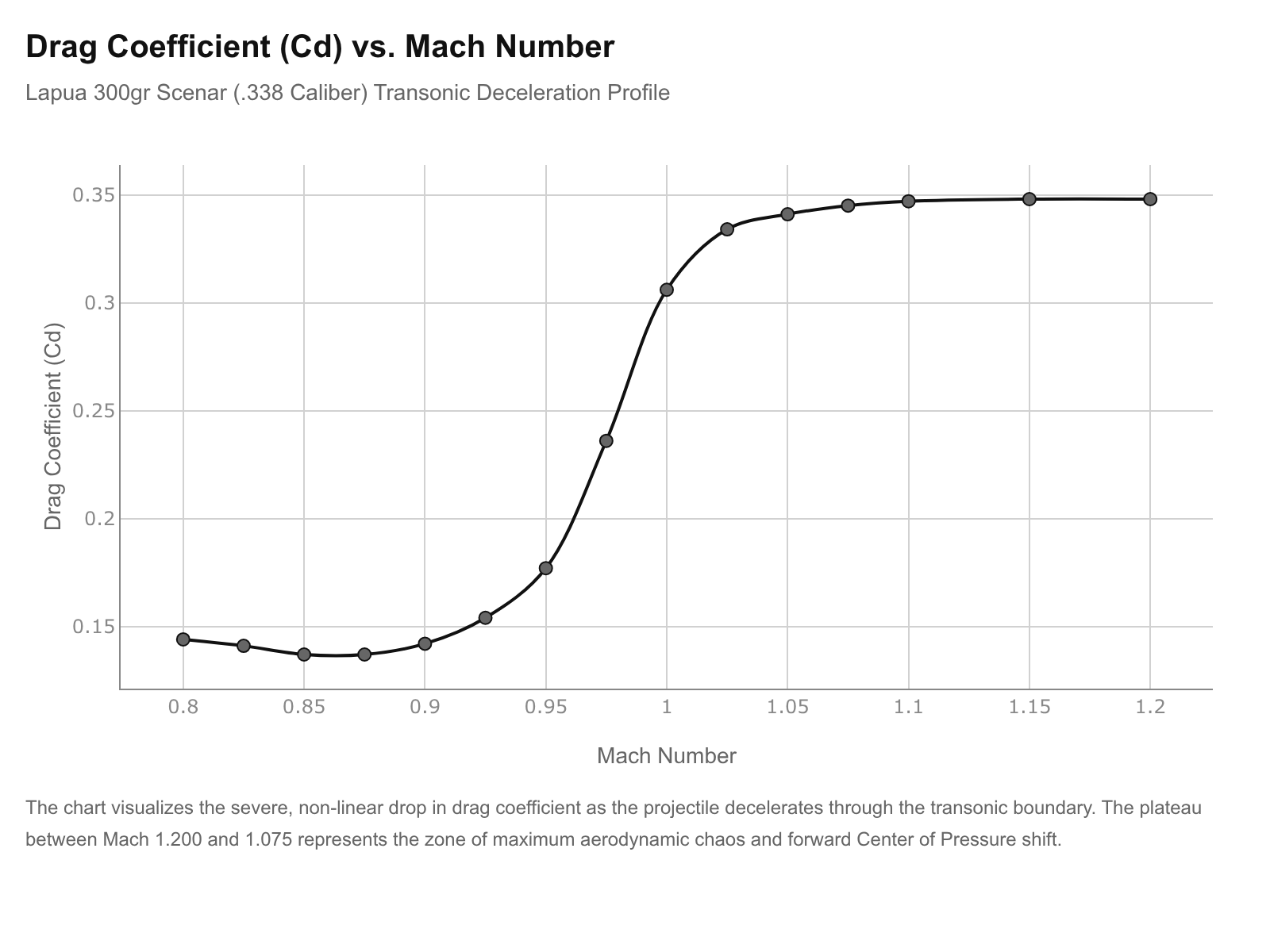
6.2 Step-by-Step Analysis of the Transonic Drag Trough
The Doppler data explicitly reveals the harsh physical reality of the “transonic wall.” At Mach 1.200, the Drag Coefficient is pinned at its absolute maximum (0.348). The bullet is fighting massive wave drag caused by the immense compression of air directly at the nose. Crucially, the Cd remains elevated and essentially flat (dropping only imperceptibly from 0.348 to 0.345) all the way down through Mach 1.075. This wide, high-drag plateau represents the period of maximum aerodynamic chaos, where Mach buffet is violently shaking the bullet laterally, and the normal Center of Pressure is shifted maximally forward, testing the absolute limits of the bullet’s gyroscopic rigidity.
As the bullet physically breaks the actual speed of sound (Mach 1.000) and drops to Mach 0.975, the data shows a massive, highly nonlinear cliff in the drag coefficient, plummeting from 0.306 to 0.236 in just a tiny 0.025 Mach step. This sudden drop physically represents the total collapse of the bow shockwave. By the time the bullet reaches Mach 0.850, the flow has smoothed out almost entirely, the turbulent rear wake has stabilized, and the Cd drops to a highly efficient 0.137. If the bullet possessed enough mathematical Dynamic Stability (Sd) to prevent the onset of limit cycle yaw during the brutal 0.348 drag plateau, it will now successfully “go to sleep” again and fly predictably in the subsonic regime. However, if it failed the dynamic stability test during that plateau, it will have yawed heavily, effectively increasing its frontal cross-sectional area and rendering these highly efficient subsonic Cd values completely moot, as the bullet is now flying partially sideways.
7.0 Projectile Geometry and Destabilization Mitigation Strategies
The physical geometry of the projectile dictates exactly how violently the Center of Pressure shifts and how severely the Mach buffet manifests across the boundary layer. In the .338 Lapua and Norma Magnum platforms, the 300-grain weight class is universally considered the gold standard for ELR engagement. Two of the most prominent, battle-tested projectiles in this specific class are the Lapua 300-grain Scenar and the Berger 300-grain Hybrid OTM Tactical.
7.1 Traditional Secant Ogive Designs: The Lapua Scenar
The Lapua Scenar is a traditional, highly refined secant-ogive, hollow-point boat-tail (HPBT) design. It possesses a G7 BC of approximately 0.392.1 The secant ogive profile features a sharp, aggressive geometric radius that pierces the air with exceptional efficiency at high supersonic speeds. However, highly aggressive secant profiles tend to be notoriously “peaky” in their drag curves. As the Scenar approaches the Mach 1.2 transonic boundary, the sharp, distinct transition points on the bullet jacket (where the ogive meets the bearing surface) can trigger abrupt, violent shockwave detachment. Because the nose is exceptionally long, the forward shift of the Center of Pressure during deceleration is highly pronounced, creating a very large overturning moment. Nevertheless, Lapua’s incredibly strict manufacturing tolerances (preventing CG offsets) and an optimized boat-tail angle allow the Scenar to transition through Mach 1 reasonably well, provided the initial muzzle spin rate is sufficient to maintain a high Sg.
7.2 The Hybrid Ogive Solution: The Berger OTM Tactical
To combat the specific transonic instability inherent in long, heavy-for-caliber secant bullets, Chief Ballistician Bryan Litz and the engineering team at Berger developed the Hybrid ogive. The Berger 300-grain Hybrid OTM features a G1 BC of 0.818 and a massive G7 BC of 0.418 to 0.421.1
The Hybrid design meticulously blends two geometric shapes into a single profile: it utilizes a tangent ogive (a smooth, continuous geometric curve matching the radius of the bullet body) where the bullet bears against the rifle’s lands, and then it seamlessly transitions into a high-efficiency secant ogive toward the meplat.3 This design not only makes the bullet significantly less sensitive to seating depth variations in the rifle chamber, but it fundamentally alters its aerodynamic signature in the transonic zone.
The smoother tangent section drastically mitigates the harshness of the shock-induced boundary layer separation. By easing the airflow separation over the nose and shoulder, the Hybrid ogive physically softens the severity of the Mach buffet vibration. Furthermore, the carefully calculated boat-tail length (0.311 inches) and specific boat-tail angle are designed to optimize base pressure recovery, helping to stabilize the volatile Magnus CP and maintain a positive dynamic damping coefficient (H) as the bullet drops below the critical 1,340 fps threshold.36
8.0 Systems Engineering and Practical Application for Tier-1 Operators
Understanding the extreme physics of transonic CP shifts and Mach buffet directly informs and mandates the hardware choices made by defense procurement officers, law enforcement armorers, and elite competitors fielding .338 magnum systems.
8.1 Twist Rate Optimization for Spin Decay Mitigation
Historically, standard-issue .338 Lapua Magnum sniper rifle barrels were manufactured with a 1-in-12 inch or 1-in-10 inch twist rate. While a 1:10 twist provides an acceptable Gyroscopic Stability (Sg) factor of around 1.4 to 1.5 at the muzzle for a 300-grain projectile, this is merely a static, sea-level metric that does not account for the violence of the transonic zone.
Because dynamic stability (Sd) is so severely threatened by the sudden forward primary CP shift and the simultaneous rearward Magnus CP shift in the transonic zone, the projectile strictly needs excess gyroscopic rigidity to act as a mechanical buffer against the negative pitch damping coefficients that cause limit cycle yaw. Therefore, the modern engineering standard for heavy .338 systems deployed in ELR is moving aggressively toward super-fast twist rates, specifically 1-in-9.3 or 1-in-9 inches.37
A faster twist rate imparts a significantly higher initial RPM at the muzzle (e.g., 240,000 RPM versus 216,000 RPM). Because axial spin decay is minimal over the total time of flight, the bullet physically approaches the Mach 1.2 transonic boundary with a significantly more rigid, heavily stabilized spin axis.20 This extra gyroscopic rigidity actively resists the immense overturning moments generated by the forward-shifting Center of Pressure, drastically reducing the physical amplitude of the pitching and yawing induced by Mach buffet. Consequently, the bullet remains pointing strictly forward, minimizing its exposed frontal area, retaining its maximum ballistic coefficient, and safely surviving the aerodynamic transition into stable subsonic flight.
8.2 Velocity Migration in Overbore Chambers
Another critical systems-level consideration is the internal ballistics of the cartridge itself. As shooters push the .338 caliber to extreme velocities using highly overbore cartridges (where the powder column volume is massive compared to the bore diameter, such as in the .338 EnABELR or wildcat magnums), they encounter a phenomenon known as velocity migration.2 In highly overbore chambers, aggressive carbon and copper fouling can cause chamber pressures and muzzle velocities to spike or degrade rapidly over a very short string of fire (e.g., losing 0.9 fps per shot before the first cleaning).2
If a ballistic solver is programmed with a muzzle velocity of 2,850 fps, but velocity migration has dropped the actual output to 2,820 fps, the bullet will reach the Mach 1.2 transonic boundary much sooner than the solver predicts. If the solver is relying on a static G7 BC rather than a Custom Drag Model (CDM), it will miscalculate the severe, non-linear drag penalty occurring at that specific transonic distance (referencing the plateau in Table 1), resulting in a guaranteed miss at ranges extending past one mile. Armorers must strictly map the velocity migration of their specific rifles and pair that data exclusively with Doppler-derived CDMs to ensure the fire control solution accurately models the transonic drag spike.
9.0 Conclusion: Mastering the Transonic Zone
The transonic aerodynamic destabilization of heavy-for-caliber .338 projectiles is not a random, unpredictable occurrence; it is the strict, unavoidable result of the fundamental fluid dynamics governing compressible airflow. As a 300-grain precision projectile drops from Mach 1.2 down to Mach 0.8, the physical breakdown of supersonic shockwaves initiates violent Mach buffet, subjecting the bullet to high-frequency, asymmetric aerodynamic hammering. Simultaneously, the primary longitudinal Center of Pressure shifts forward, rapidly increasing the overturning moment arm against the Center of Gravity, while unsteady, turbulent wake shedding causes localized rearward shifts in the critical Magnus Center of Pressure, actively degrading the bullet’s dynamic damping capabilities.
Surviving this extreme aerodynamic gauntlet requires a perfect, intentional synergy of mechanical engineering and exterior ballistics. By utilizing highly optimized projectile geometries like the hybrid tangent/secant ogive to smooth boundary layer separation, driving those projectiles with ultra-fast barrel twist rates (1:9) to generate excess, buffering gyroscopic stability, and employing Doppler-derived Custom Drag Models to map the precise, non-linear Cd migration, modern .338 weapon systems can reliably overcome transonic destabilization. Mastering these complex physical mechanics is precisely what allows today’s Tier-1 operators, defense engineers, and ELR competitors to extend the maximum effective range of small arms well beyond historical limitations, guaranteeing terminal performance at distances previously thought impossible.
Appendix: Methodology
The analytical framework of this engineering white paper relies on an exhaustive Open-Source Intelligence (OSINT) review of fluid dynamics literature, advanced computational fluid dynamics (CFD) modeling abstracts, and live-fire Doppler radar telemetry data.
The primary aerodynamic force and moment models presented in Section 2.0 and Section 3.0 are derived directly from 6-degree-of-freedom (6-DOF) modified point mass trajectory models, incorporating foundational aeroballistic physics established by modern ballisticians, the U.S. Army Research Laboratory, and aerospace engineers studying compressible flow. The specific mechanics of Center of Pressure migration (both the forward static shift and the rearward Magnus shift) and shock-induced boundary layer separation were synthesized from complex aerodynamic wind-tunnel testing documentation and CFD Detached Eddy Simulations analyzing spinning projectiles at high angles of attack. The historical aerospace comparisons (Mach tuck, Coffin Corner) were integrated to provide established, large-scale physical corollaries to the micro-scale phenomena experienced by small arms.
The mathematical derivations for Gyroscopic Stability (Sg) and Dynamic Stability (Sd) utilize standard linearized aeroballistic equations and the Don Miller Twist Rule, providing a functional, plain-text translation of complex flight dynamics suitable for mechanical analysis without reliance on proprietary simulation software. The discrete empirical data presented in Table 1 was generated by extracting specific Mach versus Drag Coefficient (Cd) telemetry points from Lapua’s published QuickTARGET Unlimited Doppler radar dataset for the GB528 Scenar 19.44g (300-grain) bullet. This methodology ensures that the theoretical fluid dynamics discussed in the report are directly grounded in observed, real-world flight characteristics of the .338 caliber projectile, providing actionable intelligence for the ELR and defense communities.
Please share the link on Facebook, Forums, with colleagues, etc. Your support is much appreciated and if you have any feedback, please email us in**@*********ps.com. If you’d like to request a report or order a reprint, please click here for the corresponding page to open in new tab.
Sources Used
- Weapon Employment Zone (WEZ) Analysis of the Optimized 300 Winchester Magnum vs 338 Lapua Magnum With Various Ammunition – Applied Ballistics, accessed February 27, 2026, https://appliedballisticsllc.com/wp-content/uploads/2021/06/ABDOC116_2_300_338_Rev1-2021-Copyright.pdf
- The 375 & 338 EnABELR Cartridges – Applied Ballistics, accessed February 27, 2026, https://appliedballisticsllc.com/the-375-338-enabelr-cartridges/
- Berger Bullets 338 Caliber ( .338″) 300 Gr. Match Tactical Hybrid OTM (Box of 100), accessed February 27, 2026, https://www.precisionreloading.com/cart.php#!l=BG&i=33109
- Transonic Flight | SKYbrary Aviation Safety, accessed February 27, 2026, https://skybrary.aero/articles/transonic-flight
- Mach Number Explained: What It Is and Why Pilots Use It – Pilot Institute, accessed February 27, 2026, https://pilotinstitute.com/mach-number-explained/
- Transonic Effects on Bullet Stability & BC | Applied Ballistics, accessed February 27, 2026, https://appliedballisticsllc.com/wp-content/uploads/2021/06/Transonic-Effects-on-Bullet-Stability-BC.pdf
- Subsonic, Transonic and Supersonic Flight – Airgun Ballistics 101, pt. 10 – YouTube, accessed February 27, 2026, https://www.youtube.com/watch?v=HpDKxVuRWto
- Subsonic and Accuracy | Shooters’ Forum, accessed February 27, 2026, https://forum.accurateshooter.com/threads/subsonic-and-accuracy.3963361/
- Brayn LITZ – External Ballistics | PDF – Scribd, accessed February 27, 2026, https://www.scribd.com/document/777012274/Brayn-LITZ-External-Ballistics
- Extending the Maximum Effective Range of Small Arms | Applied Ballistics, accessed February 27, 2026, https://appliedballisticsllc.com/wp-content/uploads/2021/06/Extending-the-Maximum-Effective-Range-of-Small-Arms.pdf
- External ballistics – Wikipedia, accessed February 27, 2026, https://en.wikipedia.org/wiki/External_ballistics
- Center of Pressure Analysis for Bullet Angle of Attack Using Computational Fluid Dynamic – AIP Publishing, accessed February 27, 2026, https://pubs.aip.org/aip/acp/article-pdf/doi/10.1063/5.0071491/14236320/030007_1_online.pdf
- Aerodynamic Analysis of Projectiles in Ground Effect at Near-Sonic Mach Numbers – Aerospace Research Central, accessed February 27, 2026, https://arc.aiaa.org/doi/pdfplus/10.2514/1.J054114
- Dynamic and Gyroscopic stability of spin-stabilized projectile with Modified Point Mass Trajectory Modeling – IJIRT Journal, accessed February 27, 2026, https://ijirt.org/publishedpaper/IJIRT172059_PAPER.pdf
- Dynamic Stability Derivatives – DTIC, accessed February 27, 2026, https://apps.dtic.mil/sti/tr/pdf/ADA624267.pdf
- CFD Prediction of M910 Projectile Aerodynamics: Unsteady Wake Effect on Magnus Moment – ResearchGate, accessed February 27, 2026, https://www.researchgate.net/publication/268555496_CFD_Prediction_of_M910_Projectile_Aerodynamics_Unsteady_Wake_Effect_on_Magnus_Moment
- From a physics perspective: why do bullets have a boat tail, instead of being perfect airfoils? : r/guns – Reddit, accessed February 27, 2026, https://www.reddit.com/r/guns/comments/2royyb/from_a_physics_perspective_why_do_bullets_have_a/
- Center of Pressure, accessed February 27, 2026, https://www.grc.nasa.gov/www/k-12/VirtualAero/BottleRocket/airplane/cp.html
- Bullet Stability Basic Theory | Hammertime Forum, accessed February 27, 2026, https://hammerbullets.com/hammertime/threads/bullet-stability-basic-theory.76/
- Ballistics Tip: Understanding Bullet Stability (Twist Rate and MV) – Accurate Shooter Bulletin, accessed February 27, 2026, https://bulletin.accurateshooter.com/2015/09/ballistics-tip-understanding-bullet-stability-twist-rate-and-mv/
- Airplane Upset Recovery Training Aid Revision 2 – FAA, accessed February 27, 2026, https://www.faa.gov/sites/faa.gov/files/pilots/training/AP_UpsetRecovery_Book.pdf
- Problems of High Speed and Altitude – Robert F. Stengel, accessed February 27, 2026, https://stengel.mycpanel.princeton.edu/MAE331Lecture24.pdf
- 7. Transonic Aerodynamics of Airfoils and Wings, accessed February 27, 2026, https://archive.aoe.vt.edu/mason/Mason_f/ConfigAeroTransonics.pdf
- Airplane Stability and Control Abzug and Larrabee – Flip eBook Pages 1-21 – AnyFlip, accessed February 27, 2026, http://anyflip.com/igbl/zhtn/basic/
- Chapter 5: Aerodynamics of Flight – FAA, accessed February 27, 2026, https://www.faa.gov/sites/faa.gov/files/07_phak_ch5_0.pdf
- FAA-H-8083-25, Pilot’s Hanbook of Aeronautical Knowledge– File 1 of 4 – Sheppard Air, accessed February 27, 2026, https://www.sheppardair.com/download/faa-h-8083-25.pdf
- Air Force Research Laboratory Technology Milestones 2007 – DTIC, accessed February 27, 2026, https://apps.dtic.mil/sti/tr/pdf/ADA480591.pdf
- (PDF) A Coning Theory of Bullet Motions – ResearchGate, accessed February 27, 2026, https://www.researchgate.net/publication/224927152_A_Coning_Theory_of_Bullet_Motions
- An Introduction to Terminal Ballistics; How Bullets Wound and Kill, accessed February 27, 2026, https://www.everydaymarksman.co/marksmanship/terminal-ballistics/
- Lapua Ballistics Tips: Stability Estimation, accessed February 27, 2026, https://www.lapua.com/lapua-ballistics-tips-stability-estimation/
- Range Report – Bullet Stability Factor Formula | Sniper’s Hide Forum, accessed February 27, 2026, https://www.snipershide.com/shooting/threads/bullet-stability-factor-formula.6988900/
- External Ballistics: Flight Dynam- ics Simulation and Projectile Aero – POLITesi, accessed February 27, 2026, https://www.politesi.polimi.it/retrieve/f153e94d-f96f-4a74-a512-552b46068bdd/2025_4_Cucchi_Tesi_01.pdf
- A review of dual-spin projectile stability – CERES Research Repository, accessed February 27, 2026, https://dspace.lib.cranfield.ac.uk/bitstreams/5759a7ca-915d-4288-aee0-39ca42dbc3d2/download
- Custom Drag Models for Extreme Long Range – Berger Bullets, accessed February 27, 2026, https://bergerbullets.com/nobsbc/custom-drag-models-for-extreme-long-range/
- Lapua Bullets Drag Coefficient Data, accessed February 27, 2026, https://www.lapua.com/wp-content/uploads/2019/03/QTU-Lapua-Edition-brochure.pdf
- Berger 33109: 338 Cal 300gr Hybrid OTM Tactical, 100/Box, accessed February 27, 2026, https://www.milehighshooting.com/berger-33109-338-cal-300-grain-hybrid-otm-tactical-100-box/
- Question: twist rate for .338 bullets | Sniper’s Hide Forum, accessed February 27, 2026, https://www.snipershide.com/shooting/threads/question-twist-rate-for-338-bullets.1092/