Category Archives: Fixing Stuff

Upgrading A Char-griller Competition Pro Model 8125 Smoker For Use WIth Firewood

As a father’s day gift this year, my kids chipped in and bought me a brand new grill. My wife helped them hide it and together they surprised me. Man, that really touched me. I’ve had a Char-griller Super Pro 5555 grill for almost 10 years – we’re not exactly sure how old it is but it was rusting through in a number of spots. The kids know that I love to grill and decided to go in together to buy me a new 8125 Competition Pro Offset Smoker Charcoal Grill. I had made a few assumptions about that grill that didn’t quite turn out as expected but with a little bit of work I was able to make a grill I really like.
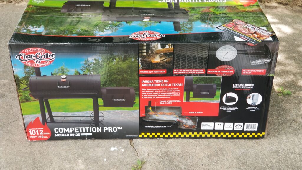
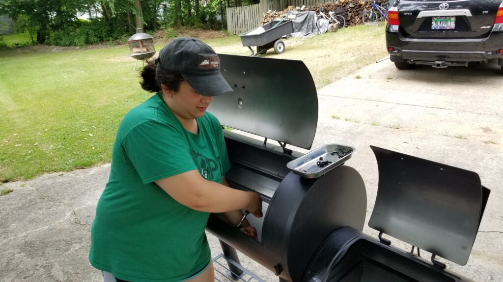
Eye catching packaging and it weighs a ton – 140 pounds.
My two daughters helped me assemble it. The size and weight of the components really make it a two person job.

My biggest problem has to do with my preference to cook with wood and not charcoal and some usability issues this created. Here are my observations after using this for a few weeks:

#1 – The 8125 was really designed with charcoal in mind and they say that right up front. It has a fairly small fixed gap between the grate that holds the charcoal and the expanded metal cooking grates. It would work for a layer or two of charcoal but not for wood.
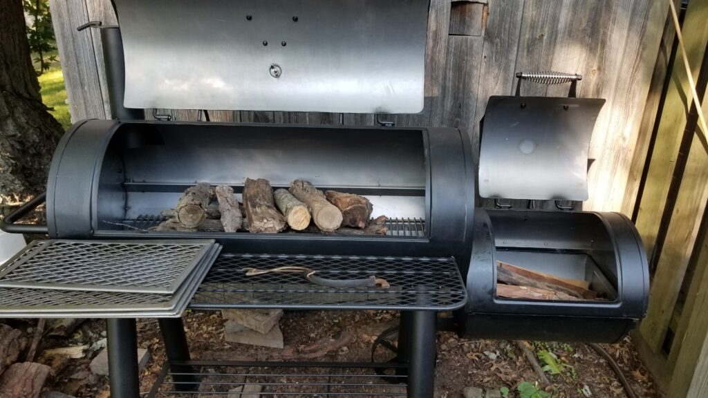
You can see there’s not much room between the lower rage and the shelf that would hold the cooking grates. Note the expanded metal food grates sitting on the left end of the shelf.

#2 – The paint they put on the 8125 flat out burns right off. What in the world were they thinking? I’m sure this is why the manual says not to exceed 400F but come on. My old grill never did that.
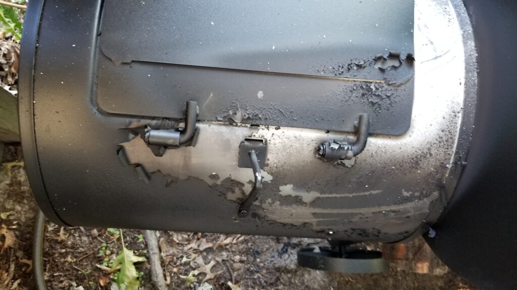
Yeah, the junk paint came right off where it got too hot. We read this might be a problem so it was entirely a surprise but for the price they could have used a high temp paint.

#3 – The expanded diamond-pattern sheet metal is really thin and doesn’t help at all when it comes to transferring heat. I prefer a heavier grate that will help conduct heat to the food.

#4 – Maybe because I am using wood but I can’t seem to run the little smoker piece as well as the big section. Not a big deal but definitely an observation. I’m not even going to worry about this and save the little side smoker box for when I do really want to smoke stuff.

So what did I do?

In looking at the grill’s performance there were three things that I needed to do – retrofit it to use wood, replace the thin expanded metal cooking grates with cast iron and to use a high-temp paint vs. whatever stuff Char-griller chose very poorly to use.

Welded Fire Plates To Burn Wood

Okay, my old grill had a relatively thin sheet metal cradle that you could raise and lower to adjust the heat. The nice thing was that I could lift it out and dump the ash. What was real important is that is shielding the bottom from the burning wood. I really wanted that.

I bought some 14 gauge mild steel and cut it into strips. I did the wings at 4″ and the base at 5″ wide. If I had it to do over, I would have done the base still at 5″ wide but the wings at about 4-1/2″ to get a tad closer to the shelves that are tack welded from the maker. You could go in with a cutting disc, cut the tacks and remove the lower shelf supports really easily if you wanted to. I decided to just leave them.
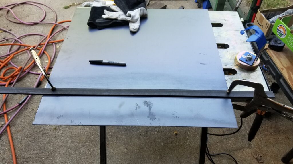
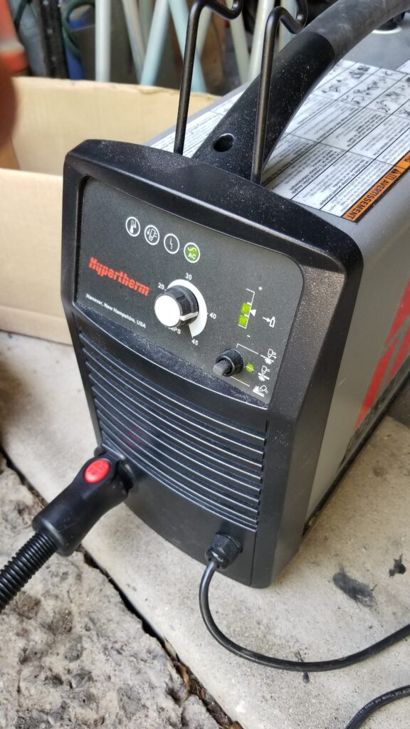
Laying out the 14ga sheet metal to cut my fire plates. The straight edge helps me make clean cuts with my Hpertherm Powermax 45 plasma cutter. I could have used a cut off wheel too but at this thickness, a plasma cutter is nice and fast. I tend to spend more time setting up than I do actually making the cut.
I’m always impressed by how fast the plasma cutter goes through steel. Wow. The Powermax 45 is nice and straight forward. Amperage, air flow is indicated on the top right and the bottom three position toggle is for the type of cut you are doing.

Yes, I did think about doing more strips because the grill’s bottom is round. That would have let me follow the contour even more closely but I just wanted to keep it simple. If I were to go this route, I would cut the strips such that they came close to 14-15″ across or whatever you want really.

To form the angles, I actually took a simple short cut. I did three small tack welds to hold the plates together – one at each end and one in the middle. I then took the assembly to the grill and pushed/whacked it into place. This caused the sides to bend up and I got just the angle I wanted with the base plate centered. I then removed the unit and did the final welds all the way around.
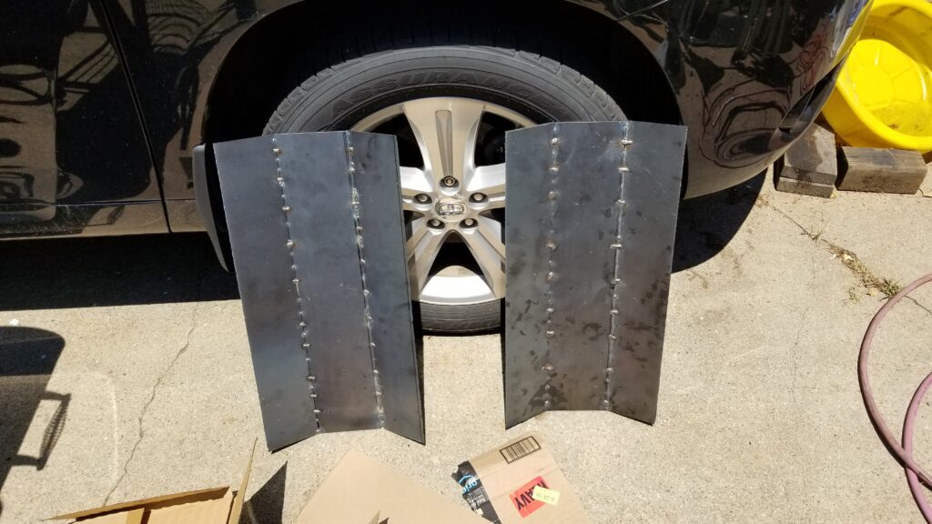
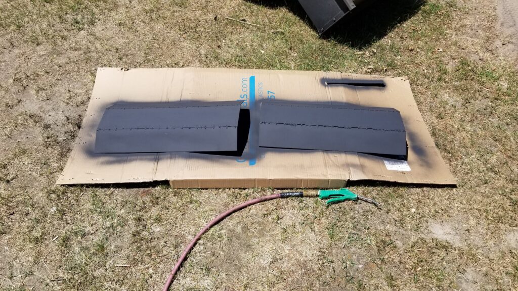
Here are the two raw plates. My next step was to paint them with 2000F paint – yes, there is such a thing.

Now the interior length of the grill is about 40-3/4″. The 14ga sheet metal I bought was 24″. I thought about cutting and welding the sheet metal but instead decided to let the two pieces simply overlap in the middle.

There are rivet nuts installed at each end of the grill to hold the legs. These stand that plates off from the bottom of the grill at each end. I put a spare piece of folded 14 ga sheet metal in the middle to lift the plates off as well.
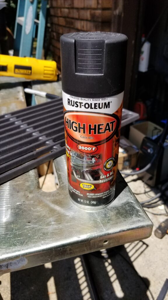
Yes, Virginia, there really is a 2000F heat resistant paint. This Rust-oleum High Heat paint is really interesting stuff and has a staged heating protocol you will need to follow to get the best temperature resistance.
I first sprayed the plates down with brake cleaner to degrease them and put on rubber gloves to avoid contaminating them with oil from my skin. Boy, they got hot in the sun and dried really fast. There are four coats on each side of the
I then installed the two plates into the grill. Next up was to load wood into the smoker unit and heat the grill up following Rust-oleum’s prescription.

Here’s what Rust-oleum recommends in case you have access to a big enough curing oven: “Bake at 400°F (204°C) for 30 minutes and allow 30 minutes to cool. Bake at 600°F (315°C) for 30 minutes and then allow 30 minutes to cool. “

In my case, I loaded the smoker up with wood and used it to heat the grill. I’d open both dampers and hit the recommended temp for at least the allocated time and then close the both dampers to smother the fire and let it cool down. My thinking, and time will tell if I am right, is that you need to hit the target temperature for bonds to be made and then cool down sets them — at least that’s what I think is happening. If it all flakes off then my assumptions will be proven flawed.

Note, I did install new grill plates and baked them at the same time so let’s talk about them next.

Bought Quality Cast Iron Grill Plates

Alright, the expanded metal cooking plates really are a joke. I’m sure they made sense to someone looking to cut cost but you really want a nice thick metal to sear meet and also to evenly spread the heat. My old 5555 grill had cast iron and they really did a nice job. Based on that, I really wanted to upgrade to heavy cast iron.

I did a lot of digging and hit on the perfect cast iron cooking grates on Amazon. These things are amazing!
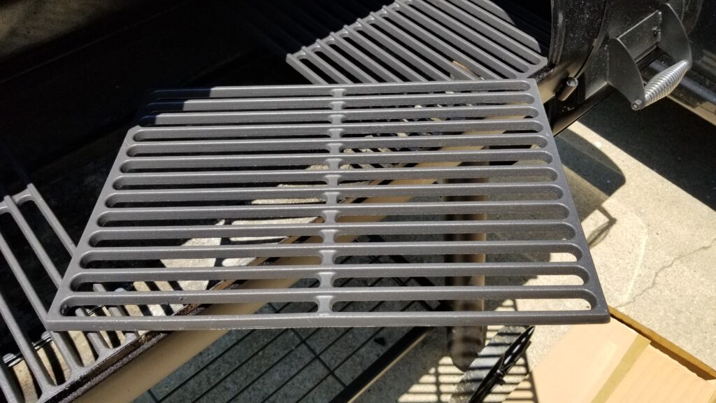
The replacement cast iron cooking grates I ordered off Amazon fit perfectly. They are very thick and heavy, which will help cook food evenly.

The grates are Vicool model 7526s https://amzn.to/3uWdwgwand measure just over 17-1/8″ deep and about 11-7/8″ wide and almost a 1/2″ thick — they are heavy! The grates come two per package and this meant I would need to order two sets to go the length of the grill.

The inside of the smoker has tabs to limit travel of the grates they installed. I could set in three complete grates. For the last grate, I marked where I needed to cut it and used a grinder with a cut off wheel to cut the last piece to size and drop it in. Since I don’t grill to the far left, that’s where I put the partial piece. It really turned out nice — I am very, very happy with these grates and definitely recommend them (the link is above or click here for the Amazon page).
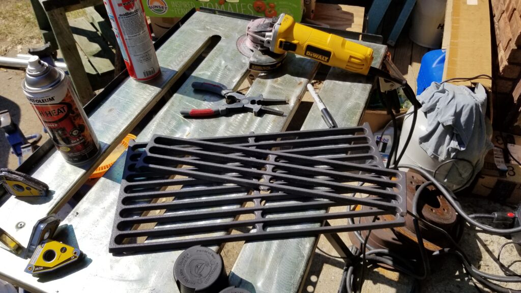
I used a cut off wheel on my Dewalt 4.5″ grinder to quickly and easily cut the piece off the last grate. I cut the piece slightly too big and then sanded it down to fit perfect. Since I will need to remove the grates too add more wood, I wanted them to not slide all over the place but also easily lift out when hot and the metal has expanded.

One last comment, these grates are heavy. Click here for the cast iron grate lifter I bought off Amazon.

By the way, there are a ton of replacement grates on Amazon. I can vouch for the Vicool ones – but click here if you want to see other options – look at the reviews and make sure they will fit, or can be made to fit, your particular grill. Amazon often tosses in stuff on searches that will not fit a given model so be careful and check.

Started Touching Up With Ruse-Oleum High Heat Ultra Spray Paint

The paint that Char-griller put on a supposed competition-grade smoker sucks. I’m not going to mince words – somebody made a very, very poor design decision. Yes, in their documentation they say not to go over 400F but why the low limit? Of course the cooking chamber or the side unit will go past that.
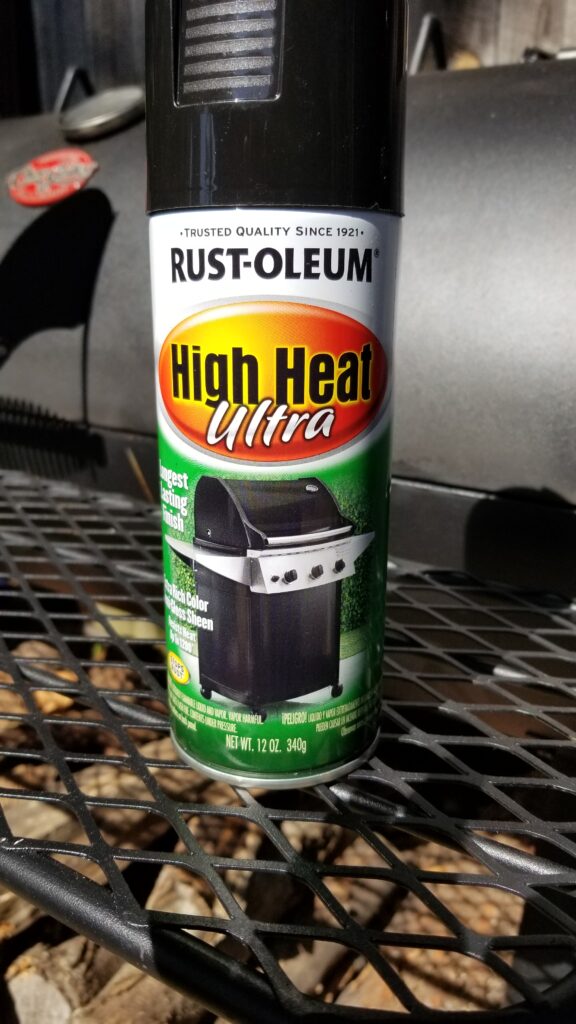
Rust-oleum High Heat Ultra is perfect for replacing the OEM paint that will literally curl and come off your grill.

Dealing with it is a nuisance but not hard and there is a good paint to use to do the touch ups. Rust-oleum High Heat Ultra comes in a semi-glass black version that works great. I use a wire brush wheel on my cordless drill to remove the loose paint and then apply 3-4 coats of the High Heat Ultra. Let it dry for at least an hour and then heat it up to 400F to cure it. Note, they do not recommend it for direct contact with flames which is why I used the 2000F paint mentioned above on my fire plates.
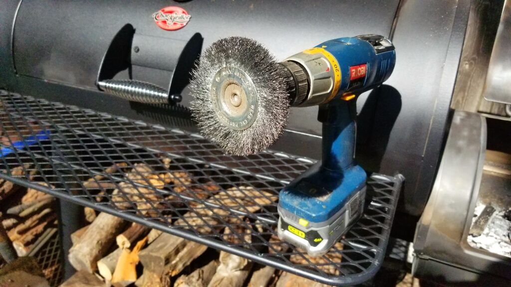
I use a wire brush in my drill to remove the curling original paint. It’s happening less and less now that the high-heat areas have largely shed the original paint.

So far, this paint has held up with no problems. When ever the original paint curls back, I wire brush it and apply the High Heat Ultra. It’s annoying but I don’t feel like using a chemical stripper to remove all the old paint so I just keep doing this over and over.

If you have a BBQ or grill that you want to touch up, this stuff rocks and you’ll see why so many people recommend it.

A Cover

I do want this grill to last so I bought a cover that fits it pretty well. It’s made by iCover and is intended to fit 60″ offset smokers. I bought it due to reviews and wanted to save some money compared to the Char-griller cover and am happy with what I got. We’ll see how it holds up over time including Michigan winters.

Hint: Break In The Grill

If you don’t break in your brand new grill, you run the risk of your food tasting funny not to mention eating some chemicals you really shouldn’t be. Before you use a grill to cook food, get it good and hot – 350-450F and hold it there for at least a half hour to get rid of paints, oils and what not. For example the 8125 came coated in some kind of oil or corrosion protection agent that needed to burn off. After that, I close the dampers and let a good coating of smoke go around and coat stuff inside and let it all cool down. After that, you ought to be ready to use it for cooking.
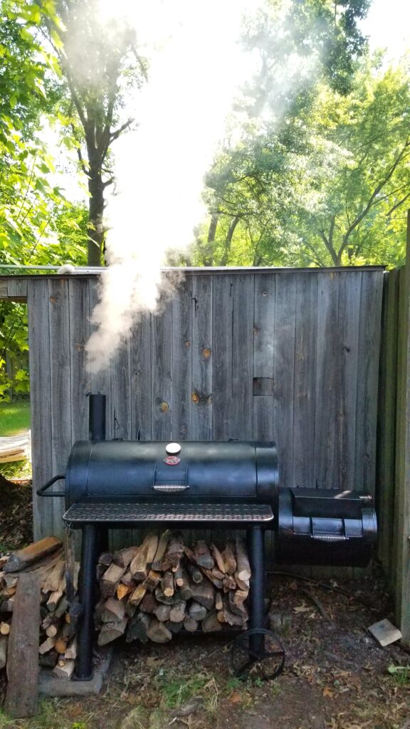
I’m seasoning the grill here. You can’t tell from the angle but there is over 6″ from the bottom of the grill to the wood. I’d stocked it up more than normal to season the grill and to get ready for cooking out that night. I split oak and maple from our property for cooking with plus whatever else my buddy John gives me such as cherry and hickory. The cherry is simply amazing to cook with.

Conclusion

My kids really surprised me this year. They knew my old grill was on its last legs and really wanted to get me something nice. They were way more upset than I was when the paint started coming off and that it really couldn’t handle the wood I wanted to burn. To be honest, the 8125 is a pretty good platform to make improvements on because they did use relatively thick sheet metal in the construction. You can take the base 8125 and make it do just what you want – that’s what I did and I honestly had some fun working out the details. I am thrilled with the result and want my kids to know they are awesome!!
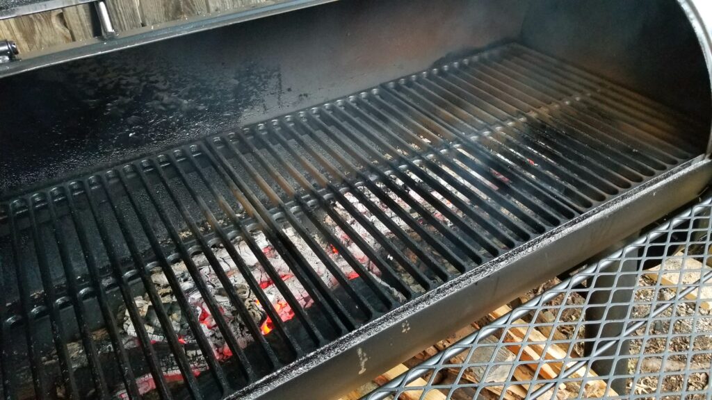

I have a nice bed of coals going on and am getting ready to do hotdogs the night of July 4th. It did a great job. Those thick cast iron grates do an awesome job of helping to both sear and cook the meat evenly thanks to their ability to conduct heat and thermal mass.
It did a great job on this chicken. The thick grates seared the meat and I could dial in the temperature right where I wanted it.
Pork steaks too!

7/21/2023 Update: I published a blog post yesterday about how the grill is holding up and refinishing it. Click here if you’d like to see the post.


If you find this post useful, please share the link on Facebook, with your friends, etc. Your support is much appreciated and if you have any feedback, please email me at in**@ro*********.com. Please note that for links to other websites, I may be paid via an affiliate program such as Avantlink, Impact, Amazon and eBay.


How to Fix A 2016 Ford Transit With a 3.7L Ecoboost Engine That Has a P051B Error Code

So, we have a 2016 Ford Transit F150 van with the 3.7 liter EcoBoost engine. It’s actually surprising how powerful that engine is because it can launch that big rectangle! However, there is an irritating recurring issue that we’ve had and that is the “P051B – Powertrain” message when the Check Engine Light (CEL) turns on. The posts and forum threads weren’t always very clear about what to do so I figured I would write about my experience to try and help people out.

How do I read ODB2 codes?

I’ve written about it in the past, I use a BAFX ODB2 scanner that connects to my Samsung phone via Bluetooth. I then use the Torque Pro app to read error codes and reset them when needed. I’ve used this combo for years and am quite happy.

Here’s the error code in Torque Pro. There is a free Torque version and a Pro without advertising. I find ads annoying so I paid some really small amount of money to go to Pro years ago and think it is totally worth it.
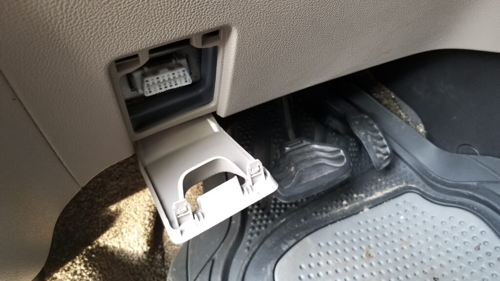
The ODB2 port is located just above and to the left of the brake pedal on the lower parts of the dash panel.

What is error code P051B?

The P051B code is returned when the engine control module (ECM), or the vehicle’s powertrain control module (PCM), has detected that the engine crankcase pressure sensor is returning values that are outside of normal operating limits. Isn’t that just great?

Remember the positive crankcase ventilation (PCV) valve and exhaust gas recirculation (EGR) system that cars had when you were younger? This is related to that – the fumes inside of the engine needs to be pulled out and burned. This improves both efficiency and emissions. The sensor is reporting back pressure changes of the EGR.

Now this is where things went sideways. I had a ton of rubbish posts to read through until I found out that Ford used a different name for the sensor plus it wasn’t exactly clear about where the sensor was located on what to order.

What does Ford call the crankcase pressure sensor?

No, they couldn’t call it something that obvious. Ford calls it the Delta Pressure Feedback EGR (DPFE) sensor. So, if you are searching all over for Ecoboost and something with pressure sensor in the search text, you’re going to find a ton of confusing crap. Try searching with DPFE instead.

Trying to find out what DPFE stood for was really bugging the hell out of me. A fellow told me to go look at the official 2016 Model year ODB guide from Ford and finally, on page 120 they define it as the Delta Pressure Feedback EGR (DPFE) sensor.

One other comment – Ford has a lot of free reference information available online but you have to hunt for it. Click here and select the option for Free Resources – that includes OBD2 guides by model year, body repair and much more.

So what can cause the P051B error code?

There are a number of things that can cause this code so let me list them in the order I would check them starting with the easiest:

  1. Is the dipstick fully inserted?
  2. Is the O-ring that seals the cap in the tube intact on the dipstick?
  3. Is the engine oil overfilled?
  4. Is there water/coolant in the oil causing it to be too full? The oil will be frothy and colored like coffee with milk in it.
  5. Are any of the PCV lines cracked or otherwise knocked off?
  6. Look inside the oil fill cap – is there a ton of sludge? If so, pull off the lines and look at the valves to see if they are filled with sludge. You can pull them regardless if you want to be sure.
  7. The pressure sensor might have failed… yeah….

For me, the last two times, it has been #7. It’s getting annoying. I’m now on my third sensor. Note, if it is the sensor then it is not critical but I do like knowing whether the check engine light is telling me something new or not so having it lit all the time is very annoying for me. In other words, you can drive with the sensor having problems but you will not know if a new code is being generated unless you hook up your scanner.

I think the sensor location was a poor choice

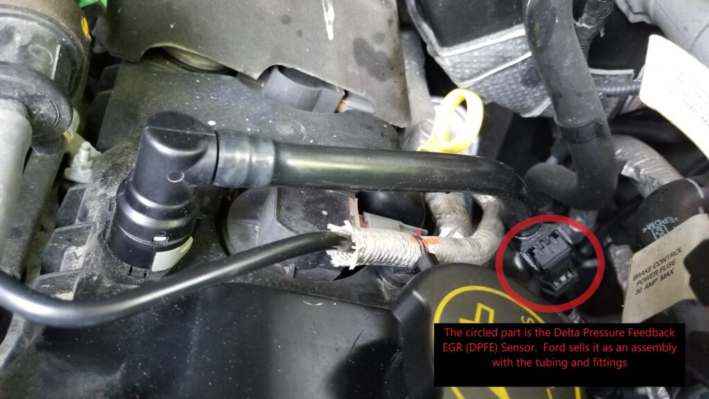
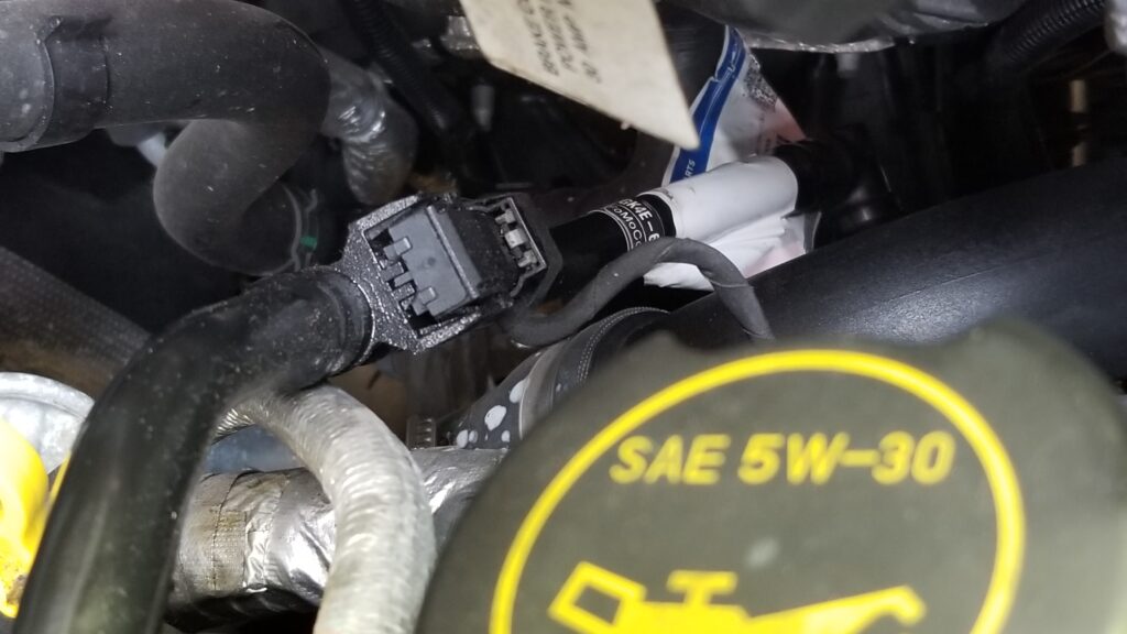
Let me tell you that it’s my opinion that the EcoBoost has a design flaw – the crankcase pressure sensor is sitting on a PVC hose and it gets fouled out by moisture and oil. The location can vary depending on your vehicle and which EcoBoost engine you have but on my 3.7L, it’s on the driver’s side of the engine,

So that’s the Delta Pressure Feedback EGR (DPFE) sensor right there in the red circle. Note the oil fill cap in the lower right of the photo to help you get your bearings.

Why they did this, I have no idea and we are now on our third sensor. The first was replaced by the dealer right after we got the van because Ford had revised the design. That sensor then failed and I replaced it myself. It turned out to be real easy.

What to order

Now this is where things get confusing. If you search hard enough, you can find just the sensor unit itself and if Rock Auto is correct, it is the DPFE-30 unit part number FR3Z-9J460-A … but it has been discontinued. I know they revised the design of the sensor to try and reduce fouling and maybe this is the older version. I returned this to Rock Auto and did not install it. I can’t confirm DPFE-30 is the correct sensor just to be clear – I think it is the older design they revised. The part that goes into the tube looked different.

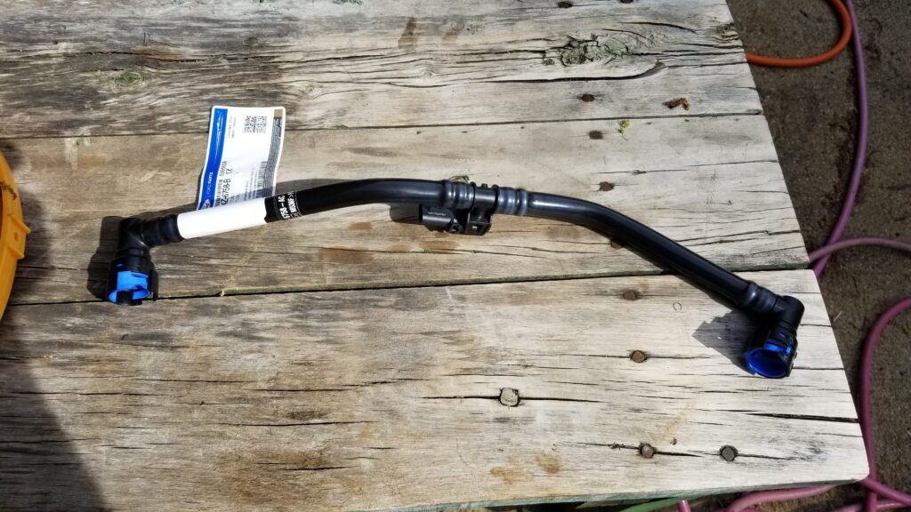
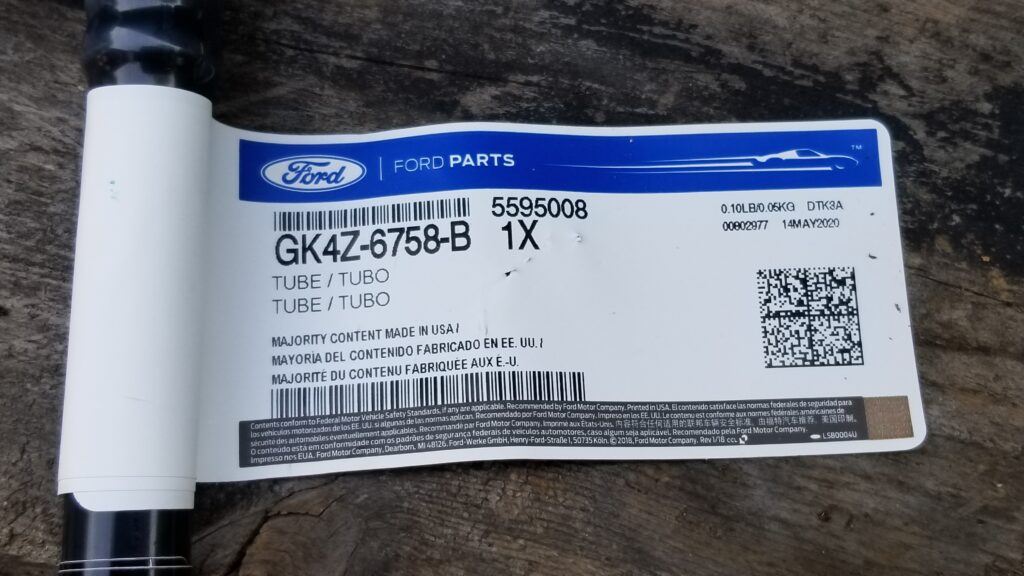
What you want to buy is the assembly that includes the tubing and the sensor. This is the current part number as of my writing this blog to the best of my knowledge: GK4Z-6758-B

Here is the brand new part fresh from the dealer – GK4Z-6758-B
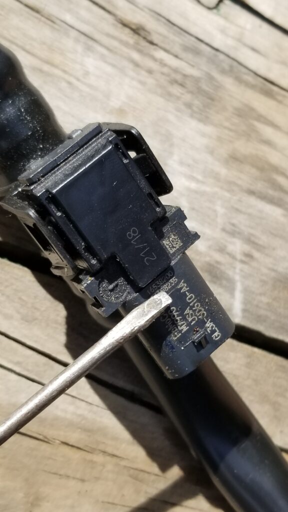
Here’s a close up of the assembly’s parts label.
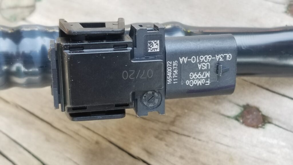
This is the sensor still on the tubes. It is held in place by the two black “Ears” – one on the top left of the sensor and one at the bottom left. Gently pry them up with a small blade screw driver and the unit comes right out.
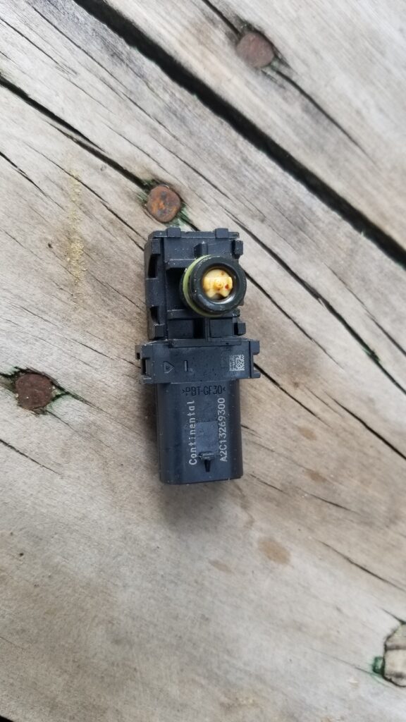
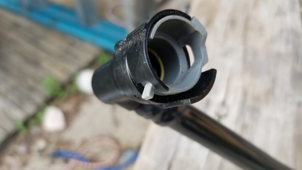
This is the part that goes into the hose.

Where to buy the GK4Z-6758-B Assembly?

Okay, you can get it from your local dealership for about $81 or you can buy it online for $38-42+S&H. We were going on a trip so I didn’t have time to wait and went with the dealer. While $81 may sound like a lot, if you mail order the part next day the price difference is less than it may first seem. [Note, prices have gone up considerably due to inflation – as of 5/18/22 it is $45-55 on eBay with free shipping.]

What I have been using more and more are vendors on eBay. You’ll see photos that look like what I showed above and also less detailed drawings that just show a tube. I’d go with reputable vendors that have quite a few reviews and as high of a rating as possible.

How to remove the old tube?

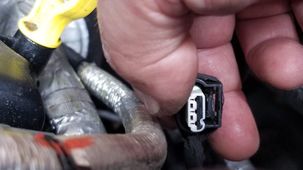
First, use a small blade screw driver to slide under the retaining tab and remove the wiring harness from the sensor. With the tab slightly up, it pulls straight back.

This is the opposite end of the sensor. You need to lift that tab up front just a tad with a small blade screw driver.
The tab just has to rise over that tiny nub just above the “GL3A” printed text near the right end to then slide off.
That little black tab above the white plastic just barely has lift up and then the plug can be pulled back off the sensor.

Next is to remove the tubing from the engine. There are quick connect fittings on each end. You just push the band’s tab out and the band moves out of the slot in the PVC fittings. It helps to look at the replacement hose first to see how the tab moves. With the tab held out, you can lift the tube straight up and off the fitting. It’s actually easy once you do the first one. Again, play with the replacement and you’ll see how it works.

It’s a novel design really. Push that little grey tab to the right and it will allow the fitting to be lifted straight up off the male plug. The one at the bottom of the engine you will need to do by feel but it is the same way – feel the tab, push it out and hold the tab out while you lift.

So, the replacement assembly took less than a minute to click back into place and reconnect the wiring assembly. Done. I cleared the code and a month later, it hasn’t come back.

Lessons learned – be careful while reading on the Internet. There are some people posting stuff that have no idea what they are talking about plus the super secret different name Ford chose to use for the sensor didn’t help matters.

Follow the troubleshooting list I wrote above and if it is the sensor, it is an easy fix. It took me about 10-15 minutes being real careful and I bet the next one will take 5 minutes max. I did have a hard time sorting through all the low-value posts and hope this helps you get your engine taken care of.

5/18/2022 Update: We’ve not had the problem again since replacing the tube & sensor assembly when I wrote this. One thing though is that I do my own oil now and only use Penzoil Platinum full synthetic. I’m not sure if the better oil is reducing particulates or not but just wanted to note that.


If you find this post useful, please share the link on Facebook, with your friends, etc. Your support is much appreciated and if you have any feedback, please email me at in**@ro*********.com. Please note that for links to other websites, I may be paid via an affiliate program such as Avantlink, Impact, Amazon and eBay.


Here Come The Mosquitoes and Ticks! Argh! How To Find Talstar P Pro Now And The M4 Sprayer

One of my favorite move lines comes from Aliens when Ellen Ripley says, “I say we take off and nuke the entire site from orbit. It’s the only way to be sure.” While I would like to do that with mosquitoes, it’s just not an option currently.

Not on the table for mosquitoes yet though it does sound effective. The collateral damage is hard to justify though 🙂

The best approach for dealing with the little winged horrors and ticks still seems to be Talstar P Pro. Seriously, we live in an area that can described as a reclaimed swamp (it really was) and the mosquitoes used to be unbearable. I blogged about this first in 2018 about my move to Talstar and using a Ryobi battery powered sprayer and then a second post in 2019 that covered my continued use of Talstar and my purchase of a My 4 Sons sprayer.

This will be our third year using it and I just applied our first dose the other night – 1oz Talstar per gallon of water and than I go spray it on the bushes, around the buildings, under the eves etc. When I went to buy more Talstar off Amazon, they would not deliver it to my area and never really explained why so I figured I better blog about where to find it and also the My 4 Sons sprayer that isn’t on Amazon any longer.

This is the 3/4 gallon (96oz) size Talstar P Professional insecticide by FMC. I have an acre and a half. I use 10-15 gallons of spray depending on what all I am treating and how heavy I am applying it. That means I use 10-15oz of Talstar per treatment (1 oz TP to 1 oz water).

Buying Talstar P Pro Insecticide

My big problem this year that I wanted to make you aware of is Amazon – at least in my case they will not deliver it to our address. I’m getting increasingly frustrated by Amazon so I now buy it off eBay:


My 4 Sons M4 Sprayer

The next thing I want to do is give you a “one year later” report on the M4 sprayer made by My 4 Sons. I’m happy to report it has held up great and their customer service was exceptional. Note, I definitely drained it completely before freezing weather set in.

This is my actual sprayer the morning of 5/2/2020

Here are some lessons learned on my part and a couple of minor issues I encountered:

  • I bought way too much hose when all I needed was to just tow it around like a golf cart and spray stuff. I took the extra hose and saved it just in case.
  • I bought all kinds of sprayer gizmos and all I use is the wand. It has a brass tip, is adjustable and worked just fine for me.
  • The red elastic straps they provided did not hold up – the tank would fall of the cart. I just went to ace hardware and bought some 1″ nylon straps with buckles and cut them to size. I told My 4 Sons about what I did and am not sure if they changed how they are securing the tank.
  • One wheel broke and My 4 sons promptly sent me a replacement at no cost
  • The gasket on the lid was goofy and they sent me an improved model at no cost

This Spring I could not find the battery charger and ordered a replacement part from them. The price was reasonable and on their website – of course I found the original shortly there after.

As mentioned, I’ve already done my first application this year and the unit is doing great – they aren’t on Amazon any longer though. I want you to know they are a reputable firm with a good product and customer service. I would recommend that you go direct to My 4 Sons.

Just to be clear, Talstar will work in any sprayer – it’s pretty much the same viscosity as water so any pump sprayer – manual or batter powered – will work. I needed something bigger because of the size of our lot.

Conclusion

The Talstar P Pro and M4 sprayer are a great combination that I would recommend to anyone trying to deal with mosquitoes. It’s cheaper than a service and way, way more effective than the cheap stuff you buy in a store.

I hope this helps you out.


If you find this post useful, please share the link on Facebook, with your friends, etc. Your support is much appreciated and if you have any feedback, please email me at in**@ro*********.com. Please note that for links to other websites, I may be paid via an affiliate program such as Avantlink, Impact, Amazon and eBay.


Restored An Almost 100 Year Old Samson 5263 3.5″ Machinists’ Vise For Regular Use

Growing up, my dad has this big rusty vise on his work bench and we’d use it for all kinds of stuff ranging from holding mower blades and axes during sharpening to bending metal for brackets and so forth. I knew it came from my grandfather’s farm in New Hampshire but not much else., When my parents moved near us, my dad brought the vise with him and installed it on a tool bench in their new garage.

Life can be harsh. I have a lot of good memories about my parents but nothing really prepares you for when they pass away. I was close to my dad and to this day, when I use one of his old tools, it makes me feel good – kind of like he’s still here and happy to see me using something of his – hopefully the right way.

At any rate, when we had to sell their house and clean stuff out, I snagged the big old vise and stuck it on the floor in the corner of my shop and really didn’t think much about it for almost five years. One day I started thinking about installing a second vise in my shop near another area where I do a lot of work that requires both work holding and a vise that can withstand 50-100 ft/lbs of torque. I figured I had two options – I have a 6″ Harbor Freight unit somewhere buried in my shop that I could dig out or I could go find my dad’s and take a closer look at it.

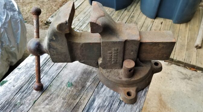
So. I dug out the old vise from under a work bench and blew off a ton of dust and dirt. The first thing that I noticed was that it weighed a ton and the second was that it was remarkably beefy and actually in really good shape other than surface rust. The action moved fairly well albeit a little gritty. Everything felt fairly tight meaning nothing seemed to be bent or broken. Last but not least, other than missing the handle on the locking nut, everything seemed to be there.

Where did Samson vises come from?

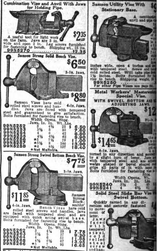
I did some searching on the web and found mention that Samson vises were sold by Sears from about 1908 to 1939 based on searching for “Samson Machinists” on ancestry.com. This page is from a 1923 Sears catalog and was copied from Vintagemachinery.org:

There it is down in the lower-left – 99N5263. A 3-1/2″ jaw width with a 5″ opening, weight was 37 pounds and cost a whopping $9.30!! Wow! Now, when my grandpa actually bought it, I have no idea. If my dad knew, he never said or I don’t recall – at this point, I’m really not sure.

By the way, in the catalog ad above, look at the weight of the 5266 5″ vise – 93 pounds! That would be a fun one to find. It must be enormous – I’ll have to keep my eye out for one 🙂

By the way, I couldn’t find a definitive answer about who made the Samson vises for Sears. Some people thought it was Reed but I haven’t confirmed that. If you search on Reed Vises, you will see some similar designs but I did not see an exact match. I emailed both Reed and Yost to see if they can share any insights. If I find out, I’ll update this post.

8/25/2020 Update: I got a very nice email from James about Samson vises based on some research he did: “Samson Vises were the Sears house brand before Craftsman took over in 1927. Samson Vises were made by Rock Island Vise Company for Sears and Roebuck out of Rock Island, Illinois.”

Restoring the old vise for regular use

Other than quite a bit of surface rust, it was really in very shape and I decided to use the old vise. The next thing I had to decide was what to do with the finish – it was rusty my whole life so I thought about just oiling the rust and sealing it. Another part wanted to fix it up. I honestly thought about it for a few days because I couldn’t do anything right away. In the end, I decided to refinish it. From what I could tell the vises were originally black and either partially or fully painted. My vise had zero paint on it anywhere.

Note: I am not doing a 100% overhaul to make it look like when it shipped from Sears. I wanted to clean it up some have it be functional. I just want to be clear in case any purists take issue with my use of the term “restoration”.

So, the first step was to disassemble the vise both to make sure it was indeed salvageable and also to clean everything. The weather wasn’t cooperating so you’ll some photos were taken indoors and some outdoors so bear with me.

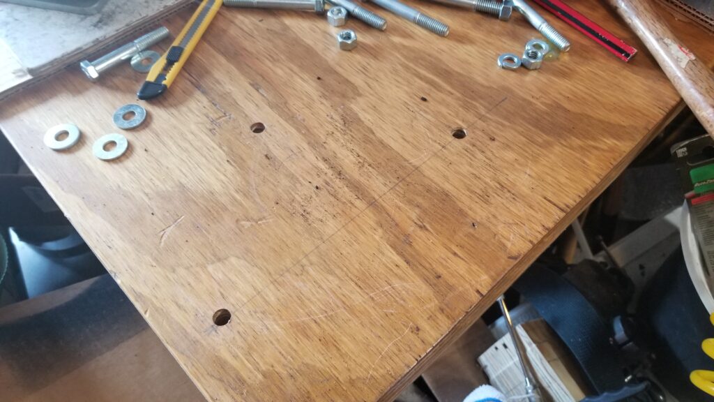
Before I took the vise apart, I mocked up where I wanted it on the bench and drilled the holes. I planned to use 3/8″ bolts to secure it and they are in the photo. The bench it is on has a top made of 1-1/2″ of plywood and weighs 5-600 pounds because of the massive steel frame I built for it.
The first thing you do is to remove the sliding jaw. This is usually done by rotating the handle until the screw exits the spindle nut in the body of the vise and the sliding jaw then pulls out. Be aware that the sliding unit can be surprisingly heavy depending on the design of the vise.
The greasy looking thing is the spindle and it was in great shape. There were remnants of old grease protecting it, the screw and the ways where the sliding jaw slid (the clear tracks on the body. There were no signs of cracks – just dirt and rust in non critical areas.
To the right of the main body of the vise is the lock nut. Normally there is a small handle on it but it’s long gone. This is basically threaded onto a bolt that protrudes us from the clamp in the base. It simply unthreads. The shiny 3/8″ grade 1 bolt to the right of it will become the new handle for it.
This is the bottom of the slide. As you can see, the machined surfaces and screw are in great shape.
Somehow I always manage to miss taking a photo. The top part of the vise is secured to the base by a heavily made axle bolt. It’s the beefy chunk of steel sitting between the base and my ball pein hammer. Surprisingly, it came out very easily with a simple adjustable wrench – I just reached in perpendicular and turned the bolt not expecting it to come loose and it did. That was a very pleasant surprise. So you can also see that the bottom surface of the static jaw assembly and the top of the base are in remarkably good shape compared to the exterior.
Here’s an even closer view of the base and the locking pad bolt. You can also see the axle nut off to the back right by the back ear of the vise even better.. I think they greased it well almost a 100 years ago and that saved the inside parts. I suppose it’s possible my grandfather or dad took it apart and lubed it but I can’t ask them now.
The weather cooperated and I took the parts outside to degrease and wire brush them.
I could have punched out pins and removed the spindle nut but I figured the vise was really solid mechanically so I took a shortcut and didn’t tear the static or sliding jaws down further.
Here’s a zoomed in photo of the static jaw’s pad. I think I can barely see a screw down on the right but it would be a heck of a chore to remove them. Honestly, the jaws were in good enough shape for me.
“72C” is marked on the base. It was the only other marking I found in addition to “Samson 5263” on the side of the static jaw’s body.
After cleaning up the static jaw, the model number was clear as day – 5263.
For the really thick rust, I used my Ingersoll-Rand needle scaler to knock it off. The external surfaces on the base of the vise were the worst.
Here’s everything after degreasing with lots of brake cleaner and the paint will be Satin Black Krylon Fusion.
Here they are from another angle.
I applied four coats of paint following the directions on the can. By the way, when a paint tells you to allow two days for it to cure and you expect it to be rubbing a lot – give it the two days. I have messed up so many finishes over the years that I now follow the directions on timing between coats and how long until a full cure.
This will be my new locking nut handle. I had to grind down the nut so it would clear the body of the vise and then I abrasive blasted the surface so the black pain will stick. It was not blasted or painted yet for this photo.
From left to right – Locking nut, locking pad, and then the axle bolt.
I found it funny to set a modern cheap 4.5″ vise next to the big Samson. Look at the difference in slides! My dad always told me to be careful and not bend the slide on the Samson. Being a kid, I did what he said without knowing much. I look at the Samson’s slide now and it would take a hell of a lot of force to bend that slide!
I greased everything with Super Lube grease. I use it a lot now because it doesn’t dry out fast and has fine particles of PTFE in it to help with lubrication. I kid you not, I coated threads, surfaces, everything!
Boy did it turn smoothly on the base!
It looks and feels like new – with some character marks of course. She is around 100 years old!
The purplish tinge is the Super Lube grease. I literally coated all sliding surfaces to try and get stuff coated. I then wiped it down after this photo. Note that it also shows at the back that the vise is not perfectly concentric. It’s still tight but not perfectly centered on the base – my guess is that it never was. We’re talking being off center by about a 1/16th of an inch or less.
Here’s the locking nut with the finished 3/8″ bolt that serves as the new sliding handle. I applied blue LocTite to the nut to secure it. Note that I can turn the vise and use it from either direction on the bench. Right now it is rotated away from the side of the bench where I primarily plan to use it.
From McMaster I ordered 3.5″ copper Wilton jaw pad covers. My 4″ Wilton has original brass covers that are beefier but these copper units will work.
So you put the pads in your vise and then tap down the surfaces including the small ears on the left and right sides. The Samson is asymmetrical so I labeled the front pad so when I remove them I don’t have to fumble around figuring out which pad goes to the front and which to the back.
I also bought some Mission Automotive plastic pads that are held in place by strong magnets. These come in handy for delicate surfaces.

Conclusion

So the vise is back in use. Every time I use it, I feel good about it and hope my dad approves.


If you find this post useful, please share the link on Facebook, with your friends, etc. Your support is much appreciated and if you have any feedback, please email me at in**@ro*********.com. Please note that for links to other websites, I may be paid via an affiliate program such as Avantlink, Impact, Amazon and eBay.


How To Fix A Broken Vacuum Line Fitting on the Air Box or Air Filter Housing Of A 2008 Toyota Highlander And Other Models – It’s Easy and Cheap!

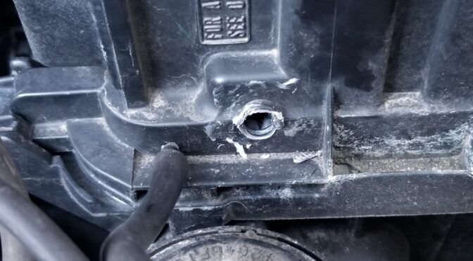
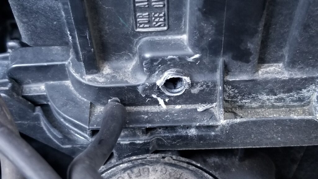
I’m going to leverage my inner Forrest Gump – used cars are like a box of chocolates. You never know what you are going to get. In this case, it was our 2008 Toyota Highlander. I decided to check the air filter just in case and noticed both that the vacuum lines had cracked and that someone had done a “creative” fix on a 4mm vacuum port that had snapped off.

So this vaccum line was just resting in the hole. There’s some white glue – maybe silicone and som odd metal insert.

If there’s one thing I have learned with modern computerized cars – don’t mess with their sensors or vacuum lines. You can get odd random codes thrown, lose performance, fuel efficiency, etc. So, I knew this needed to be fixed. The big problem – the vacuum fitting was cast into the airbox!! By the way, the air box is the car part that holds the air filter in this case – the air filter housing is another way of thinking of the part.

Let me start by telling you the expensive and time consuming way – buy a replacement air box. Yeah, this is going to cost you a bundle. A OEM Toyota air box will run you $275-400, used is about $100-185 and aftermarket tends to be under $60-90 and maybe iffy quality. Then there is the labor to do the actual swap – it’s going to either take your time or you are going to pay a mechanic to do it and the cost is going to go up fast. There is an easier and faster way.

My Recommended Approach

The magic fraction for today is 5/32″. Why? Because 5/32″ is almost exactly 4mm. If we get a small brass, aluminum or stainless barbed 5/32″ hose fitting with a threaded rear, we can easily fix this. I live in a rural area and this isn’t something I can easily walk into a hardware store and find so I did some searching for NPT to 5/32″ hose barb and found both 1/16″ NPT and metric fittings plus some were brass, aluminum and mystery metal. I discounted anything plastic/nylon because I wanted a stronger fitting.

Another reason I went with 1/16″ NPT is that it can fill a pretty big hole all by itself up to about 0.31″ given the taper plus I could then use a 1/16″ to 1/8″ bushing adapter if I needed to go larger.

After much digging around using Google and Amazon, I opted for an Aeromotive #15630 hose fitting made from 6061-T6 aluminum that I did order off Amazon [click here for the Amazon listing]. There was a no-name generic brass one but no spec so I didn’t go with it. By the way, searching for fittings like this really shows the limitations of general search engines to find parts. I spent a ton of time filtering through tons and tons of search results that turned up the wrong products. What a headache.

Aeromotive 15630 fitting that has 1/16″ NPT thread on ne end and a 5/32″ hose barb on the other.

Installation

The first thing to point out is that the molded vacuum fitting is above the air cleaner so you can safely work on the box without removing it from the vehicle! Any debris from drilling or sanding will land on the filter and you can vacuum it out later. If you have a used car, peak inside and make sure the air cleaner is there and intact.

If you have just the old busted remains of the hose fitting to contend with then Dremel or sand the area flat. You want the installed barb to be able to sit flat against the wall of the box.

Next, pick a drill bit that is just the same size as the tapered bottom of the thread. NPT thread is tapered so the bottom has a smaller diameter than the top. If the air box was steel, we would use a letter “C” drill bit to make a 0.242″ hole. Notice how this is slightly smaller than 1/4″ but I am betting most people do not have lettered drill bit sets so you pick a close size and run with it. We do want the hole slightly smaller in order to thread it. Because this is plastic, we are going to push forward with the metal adapter fitting while turning and let the thread on the adapter cut the thread into the plastic. We aren’t going to bother tapping it first. That’s right – don’t buy a tap to do this uness you are a tool junky and perfectionist, which is fine if you are – I get accused of that a lot.

I’d recommend you start with a bit smaller than 1/4″ where the bit is slightly smaller than the bottom of the adapter, drill the hole and see if you can press it in. If not, go to a bigger bit. If you mess up and have a slightly too big hole, all is not lost – read the “Well crap” section below 🙂

Let’s say that everything goes great and you can screw the fitting into the plastic – Once threaded in, it’s done. Just screw it in and quit. Don’t put too much torque or you can strip it. That works just fine unless the previous guy bubba’d it, which takes us to the next part of the story.

Well crap….

In my case, I had a box of chocolates moment. The previous owner or a mechanic had drilled the hole out and installed some small metal bushing that was hidden due to the white silicone on it. I have no idea what it was from. Once I discovered and removed it, the hole in the air box turned out to be just a tad bigger than the entire 1/16″ tapered thread. Argh… not what I wanted to deal with.

Dear bubba, thank you for hiding this under the white silicone. You just made my fix a bit more complex but not impossible.

Okay, I wanted to get this job and had three options, go to the hardware store and try and find a 1/16 to 1/8″ bushing, install a 1/16″ NP threaded nut on the back to hold it in position, which I also did not have, or glue the hell out of it and call it even.

Because I am always working on cars and pressure systems due to Ronin’s Grips, did have a tube of black Permatex Optimum Black Gasket Maker that I could use. Being black, it wouldn’t be so glaringly obvious. By the way, I opted not to use epoxy due to the flexible plastic walls and expected vibrations that might break down the bond with time. [2/12/24 Note: I think Permatex dropped the Optimum series and their Black Ultra should work just fine – I’m linking to the Amazon listing]

This is what I had on hand at the time and worked great. I could have used any quality black silicone RTV glue/gasket maker and gotten the same results. I tend to either have Permatex or LocTite brand products that I use the most.

First, I scuffed the surface around the hole with 100 grit sand paper so the glue could get a better grab on the surface. The second thing I did was to spray brake cleaner on the area to remove any trace oils that might prevent a good bond.

I was wearing nitrile gloves and also sprayed brake cleaner on the fitting to make sure it was clean. Gloves both keep your hands clean and also prevent you from getting oils from your skin on the parts — assuming the gloves are clean of course. Having a clean surface makes a HUGE difference in terms of how well any glue is going to stick.

Next, I applied a bead around the top of the NPT thread of the fitting and pushed it into the hole. Since I was wearing nitrile gloves, I just took a finger and smoothed the glue out a bit and let it cure for about an hour or so. You want it cured enough to hold the adapter in place – you don’t need it fully cured yet. With warmer weather it will cure faster and in cold weather it my take a long time and need a hot light or something to warm it up above 70F to get things done. Depending on what I am working on, I try to get somewhere between 60-110F. The warmer it is, the faster it will cure but don’t burn it or melt the plastic either!

This is the first pass. It’s not pretty but it will dry strong enough to hold the fitting in place while the second thicker coat is applied.

I then put a second layer of black gasket maker on and fanned it out to get a good grip and to securely hold the fitting. I then let this all cure overnight. I’ve learned long ago not to rush faster than what the adhesive’s manufacturer recommends or you are liable to ruin an otherwise good job.

Here is the second heavier coat this was meant to reinforce the part.

So, once it was fully cured I then needed to change the cracked vacuum lines which are what I noticed in the first place.

4mm Vacuum Lines

What got me started on all this in the first place was noticing that two 4mm vacuum lines were very cracked where they slid onto their respective hose barbs. This happens as rubber ages and gets brittle so finding them wasn’t surprising.

This is one of the ends that was badly split.

Fixing this is easy. You just need either real 4mm vacuum hose or 5/32 vacuum hose. You can either go with one formulated from rubber or more expensive silicone. The advantage to the latter is that it ought to last longer.

Because we own a number of aging Toyotas, I bought an assortment bag of metric sized silicone vacuum hose of Amazon some time ago. It comes with 4mm x 82″, and the 52″ lengths of 6mm, 8mm, and 12mm. It was expensive but now I have an assortment for when I need to repair small lines such as this case. [2/12/24 the vendor I bought from years ago is gone. Check out these listings of sets on Amazon – go with a vendor that has at least 30 ratings of 4-5 stars]

You can see the two pieces I replaced because the new silicone hose is shiny black and a thicker diameter.

Conclusion

Going this route saved us a ton hundreds of dollars and has held up just fine. I did this repair last fall and have not had a single problem. Yeah, the glue does make it a big of a bubba fix but it is revsersible and the fitting isn’t going to fall out. The black gasket maker has held the little barb in just fine and the hose is very supple and shows no wear at all. I hope this helps you out as well.

2/12/24 Update: My repair is still just fine. A reader pinged me that none of the Amazon links worked so I went through and updated them.

7/28/2023 Update: Everything is holding up just fine and we’ve put quite a few miles on the car since this was written in March of 2020.

4/9/2021 Update: Still holding just fine. Not one problem to report.


If you find this post useful, please share the link on Facebook, with your friends, etc. Your support is much appreciated and if you have any feedback, please email me at in**@ro*********.com. Please note that for links to other websites, I may be paid via an affiliate program such as Avantlink, Impact, Amazon and eBay.


Why The Mophorn Pneumatic Lift Is a Huge Help When Working On Cars and Trucks But Has One Small Issue You Need To Address

Nothing like getting old and realizing that most of your joints hate you. I bring this up because I have two manual pump floor jacks that I have used countless times over the years and the oldest is probably 25 years old – literally. Well, let me put it this way – I had no problem pumping the handle to lift cars and trucks 25 years ago but starting about two years ago, the action really started to cause elbow and shoulder injuries I had to flare up. It got so bad that I had to make a choice either to stop working on vehicles or to find a different approach.

I work on cars and trucks in our driveway so a permanently installed lift was not an option. It had to be something portable. My first thought was to get a low profile air-over-hydraulic jack that is mounted in its own wheeled carrier. They have an incredible lifting capacity (around 22 tons) but they are heavy (around 80 pounds), slow (air over hydraulic is many things but fast is not one of them) and expensive (they start around $200 and just go up from there). What really stopped me was the weight and the cost. I can’t lift or drag as much weight as I used to and the entry-level units were a tad more than I wanted to spend.

So, I kept digging and ran across pneumatic/air jacks. Think of the air suspensions you see under a big rig. Basically one or more air bladders fill with air and lift the top of the jack. They max out in terms of lift height around 18 inches and 3 tons of lift but it depends on the model. Definitely spend some time researching before you buy. I found that I needed to think about:

  • How low I needed the unit to collapse down to fit under our cars to get in position prior to lifting
  • How much weight did I need to lift
  • How high I needed the unit to lift
  • How much did it weigh?
  • What was it going to cost?

I then started reading listings on Amazon plus paying careful attention to review scores. I also talked to a mechanic friend of mine about the safety of the unit and what his thoughts were. He told me to consider two things: 1) always immediately put jack stands in place and 2) don’t lave the unit out in the sun and weather thus harming the rubber. Those suggestions made a lot of sense to me.

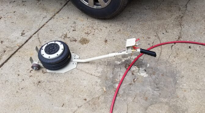
On January 8, 2019, I wound up buying a Mophorn Pneumatic Jack, 3 Ton, Triple Air Bag, with a 16″ lift height for about $150 with free shipping. The unit arrived with just little bit of assembly needed. I recall I had to install the handle and the pressure line but that was it.

I get about 15″ of lift at 90 PSI.
Left lever is the exhaust and due to the lever design, you can adjust how slow you want to drain air out. Even if you hit it and have an “oh shit” moment, you typically have a few seconds before the vehicle starts to go down. The middle unit with the pull ring is the safety blow off valve. The far right lever is the air inlet and there is a Milton M-series male plug under the Milton quick connect female fitting. If you want a reliable air system, use Milton fittings – they last.

As you can guess from the sticker above, the lift is made in China and the instruction sheet is pretty terse but it’s really not that hard to figure out. I do want to cover a few specifications with you and convert them from metric to US customary measures – these are from the owner’s manual included in the kit unless otherwise noted:

DescriptionMetricUS
Capacity3,000 kg6,613 lbs
Air Pressure5-10 Kg/cm^271 to 142 PSI
Air pressure from label on handle – presumably the recommended pressure8 kg/cm^2113 PSI
Minimum Height145mm5.71 in
Maximum Height400mm15.75 in
Lifting Time5 seconds5 seconds
Working Temperature-69C to +50C-92F to 122F

What have I lifted with it?

When I say “lift”, I am talking about the front end or the back end – not the whole vehicle.

  • 1994 Toyota Corolla DX
  • 1996 Toyota Land Cruiser
  • 2000 Toyota Camry
  • 2006 Toyota Solara
  • 2008 Toyota Highlander
  • 2016 Ford F150 Transit
  • Others more or less along the lines of a Camry or Highlander

There are a few things I have noticed

First, let me point out that I like this unit and would recommend it but there are a few things I want to point out:

  • The highest my lift will go is 15″ and that may be a function of my only running 90 PSI to the jack
  • I don’t think it actually can lift 3 tons. It bogs down on the front of our old 96 Landcruiser and also our full size F150 Transit. Again, I think it’s my lower air pressure. This summer I might plumb a dedicated 120 PSI line and see what that does. It will depend on time and money.
  • There are stabilizing cones made from steel inside the jack. Maybe 1 in 20 lifts they need a whack to start coming down. I may polish and lube these if I get a chance.
  • The rubber is pretty thick on the bladders. With that said, I do store it indoors away from the sun and the weather. I’m writing this a year later and the bladders show zero signs of wear.

The One Little Thing You Must Do: Blue Loctite Your Screws!!

I have used my jack many times since I bought it. Starting around September I was hearing faint air leak and thought the jack had bent. When I had time I found out that the bottom screws had loosened up and air was simply escaping from between the gasket and the bottom plate. I was surprised and disappointed to note that none of the screws had any thread locker applied to any of them. Many were in varying states of coming lose.

The unit is well made. The air bladders secure to that steel plate you see on them and then that assembly bolt to the dolly.
It’s the screws that attach the bladder to the while disc-shaped plate in the previous photo that came loose. Here are the metal stabilizing cones. I wish I had polished and lubed them when I had it apart and will go back and do that at some point. I did apply air tool oil to the cones after cleaning them of a gritty dust that probably dated back to when they were manufactured.
Before re-assembly I put a thin bead of Permatex Blue RTV gasket seal on the rubber gasket and then applied Blue medium-strength Loctite to each srew and brought them down lightly. I then went criss-cross lightly bringing down each screw to firm and then applied a final torque of 11 NM (about 8 ft-lbs or 97 in-lbs.

I then did the same thing to the top plate as well just to play it safe. No more leaks.

The reassembled bladder assembly then screws back down to the baseplate of the dolly. Note, this photo is actually from when I was taking it apart. The screws were so scuffed up that I just replaced them. Did I mention I use this a lot?

The following is the exact jack on Amazon that I bought and this review is about:

Bottom Line

I would buy this again and recommend it as well – just due the Loctite thing I mentioned. Note there are other Chinese suppliers on Amazon also but they do not get as good of reviews as the Mophorn units so my recommendation is only for that brand.


If you find this post useful, please share the link on Facebook, with your friends, etc. Your support is much appreciated and if you have any feedback, please email me at in**@ro*********.com. Please note that for links to other websites, I may be paid via an affiliate program such as Avantlink, Impact, Amazon and eBay.


How To Wash Your Baseball Caps Easily Without Hurting Them

Folks, as my wife will tell you, I like my baseball-style caps and seem to have accumulated a ton of them over the years. With that said, there seem to be just a handful of them that I wear all the time. The problem was that they got pretty dirty with use so what should one do?

I tried putting one in the clothes washer once and ruined my favorite hat at the time. So, since I didn’t have a way to wash my hats, I wound up having piles of “wearable in public” hats, work hats that look bad but feel good and “oh man this is filthy but I don’t want to throw it away in case I ever figure out how to clean it” hats. In the back of my head, I knew I wanted to find a way to wash them but never seemed to find the time.

How To Clean A Ball Cap

One quick comment – what I am about to tell you works on modern caps with plastic liners in the brim (the part that sticks out). Prior to 1983-ish, the liners were often cardboard and getting them wet would ruin them. If you flick the brim of an old hat and it sounds hollow, it’s probably cardboard and you should not do what I am about to outline. All of my hats are modern and have plastic liners.

One day while reading, I ran across the solution and it was so easy I was skeptical that it could work. Not only did it work, but it worked amazingly well. The near miracle fix is to hand wash your hats so they don’t get beat up. You soak your hats in a soapy solution using HE clothes washing soap. In our case, we use Tide for our clothes and that’s what I used. Note, don’t use a detergent with bleach or your hats will fade.

I took a bucket, poured in about a 1/4-1/3 cup of Tide HE and then just over a gallon of warm water. I took my dirtiest “what do I have to lose” hats and let them soak for a few hours, came in and pushed them around in the water to break things up and then let them sit another few hours – these hats were incredibly dirty folks. I was working outside and forgot about the first test batch and they probably soaked for 6-8 hours at least with no ill effects.

There are two hats in there with this load. The first time out I probably had six really dirty hats in there.

With everything wet, I really was just hoping they were done and rinsed them 2-3 times. I then hung them to drip dry in our shower. I’ve since found that even a small fan pointed at the hats speeds up drying dramatically.

Dripping dry – a small fan pointed in their direction dried these two in just a few hours.

The results were remarkable. Oil and sweat marks largely disappeared. Detergents are pretty remarkable – these days, they include enzymes to help break things down and they probably played a role on cleaning the hats so well. Tide Original, which we have, includes three enzymes – amaylase (starch based stains), mannanase (vegetable based stains) and protease (for protein based stains). Seriously, some of the hats were horribly dirty and now they are clean!!

I’ve now got all my hats back in service and they look great. This means my favorite work and shooting hats are back in business! I’m going to guess I’ve done about four batches of hats – maybe a bit over a dozen or so and 3-4 of them have been washed twice. In other words, I’ve done this a number of times and it really seems to work well.

Now that I know how easy it is, I can routinely clean my hats. I’m really happy with the results and hope this helps you out.

By the way, here are some links to what others did so you have some other perspectives to consider:


If you find this post useful, please share the link on Facebook, with your friends, etc. Your support is much appreciated and if you have any feedback, please email me at in**@ro*********.com. Please note that for links to other websites, I may be paid via an affiliate program such as Avantlink, Impact, Amazon and eBay.


How To Run Oil-Lubricated Air Compressors in Cold Weather & Not Trip Breakers

Folks, my shop is unheated and the space where my 60 gallon oil lubricated Ingersoll Rand (IR) 2340L5-V sits can get well below freezing – sometimes even well under 20F. That presents a challenge because the lubricating oil gets thicker as it gets colder and this puts more and more of a load on the motor to start. What usually results is a tripped breaker -I know my 30amp breaker would trip regularly until I took some corrective actions.

One option you can run with is to run variable weight thinner synthetic oil in the winter. I don’t want to run into issues with my pump so I stick with IR straight weight compressor oil so I’m not really keen on doing that. There are guys who will disagree with me and that’s why I point out the option.

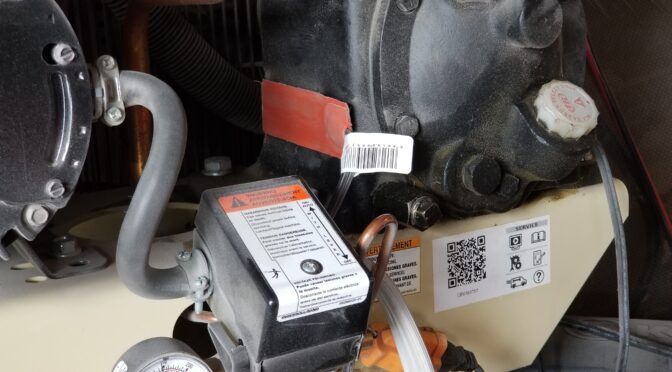
The solution I put in place works great. I simply put two Kat’s 24025 25 watt heating pads that measure 1″x5″ on each side of my pump level next to the oil reservoir. These heaters were designed to warm fluid reservoirs including those with oil. I’ve used a ton of them over the years for warming pressure tanks and what have you and have not had one fail yet. My oldest units are probably 3-5 years old and no problems — I just use them during the Winter.

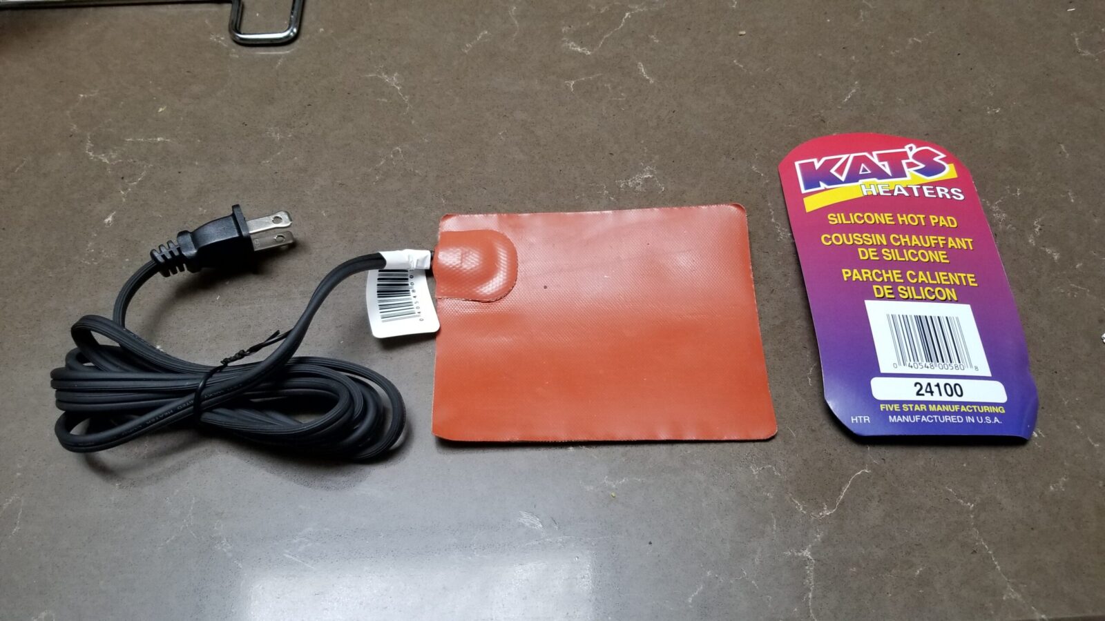
This is the Kat’s 24100 4×5 heater that I have at the bottom of my compressor to keep the condensate from freezing.

In terms of heating my compressor’s pump, I just run mine non-stop in the Winter but if you’d really rather only run them when it is at or below freezing, there are thermal power plug adapters that only turn on when it is that cold. Note, at 25 watts they do not heat fast. If your pump is real cold it could take it a while to get up to an acceptable temperature. That’s one reason why I just let them run and I can turn the compressor off independent of the heaters.

Along with the little 1×5 units, I use one larger 4×5 Kat’s 24100 pad at the bottom of my compressor to allow me to drain the condensate that would otherwise freeze. I do not run that non-stop as it is 100 watts. It’s on a thermally switched outlet that turns on at 35F and off at 45F. Yeah, it may run more than I need it to but I haven’t invested in a better controller yet for that part. I will list the digital controller I plan on getting some day so you can decide.

Installing is about as easy as it can get. The Kat’s units have a self-adhesive back and must be installed before you plug them in or you will ruin them. Clean the surface of oil and dust, peel the cover off the adhesive, stock the heater on and wait the prescribed time then plug it in and it warms up. Note, I have only used them on steel surfaces. They get hot and I would not be inclined to install them on plastic for example.

Kat’s products are made by Five Star Manufacturing and they have a ton of different products for different applications. Click here for their website.

Note: There aren’t as many Kat’s brand heating pads around now but there are a lot of different brands and sizes on Amazon – click here to see them.https://amzn.to/3J1Hpzn

The setup works great. No more tripping breakers due to thick oil caused by cold weather. I hope it helps you out.


If you find this post useful, please share the link on Facebook, with your friends, etc. Your support is much appreciated and if you have any feedback, please email me at in**@ro*********.com. Please note that for links to other websites, I may be paid via an affiliate program such as Avantlink, Impact, Amazon and eBay.