July 2026: A reader reached out that the NASA link was gone and our self-hosted copy was broken as well. After some searching, I could not find the file at NASA any longer but I could fix the link to our PDF copy. The corrected link is at the bottom of the post.
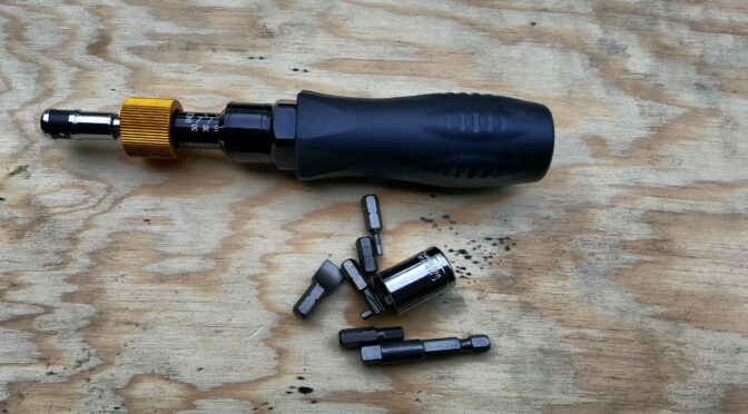
We’ve all been there – you’re working on a project and wondering how much to torque something so either we don’t bother or just take a guess. What I only found out recently was that in 2017, NASA published a really cool guide called “Installation Torque Tables for Noncritical Applications” – with the document ID as NASA/TM—2017-219475.
The document provides the torque specifications for a ton of general purpose fasteners that do not have an exact specification assigned – hence the term non-critical. As you can imagine, they get very specific in critical/risky situations.
At any rate, given the size of the bolt or screw, the thread pitch, the material and the depth, they provide a reference torque specification you can follow for both metric (M6, M8, M10, etc.) and SAE (#8, #10, 1/8, 1/4, 3/8, etc.) fasteners. Note, they provide an assembly torque (which is a 65% load from failure) and 100% torque. I use the assembly torque spec.
They also recommend that the depth of thread engagement be 1.5x the diameter of the fastener. So a 1/4″ (0.25″) fastener should have at least 0.25″ x 1.5 = .375″ (3/8″).
Here’s an example table. This is for fasteners going into 6061-T6 aluminum with a thread depth of 3/16″. If we go down for a 10-32 UNF screw, the assembly torque is 22.2 inch pounds. I’d use that lacking any other detailed information. I could go up to 34.2 inch pounds but I have stripped so many fasteners I don’t risk it. I’m a huge fan of Loctite so I go with that and the assembly spec.
Kudos to the two authors and to NASA for making it available. The PDF is a cool reference document and one I use whenever I can’t find a specific torque value for a given application. All you machinists and engineers – you know way more than me so please let me know if you have other resources you recommend.
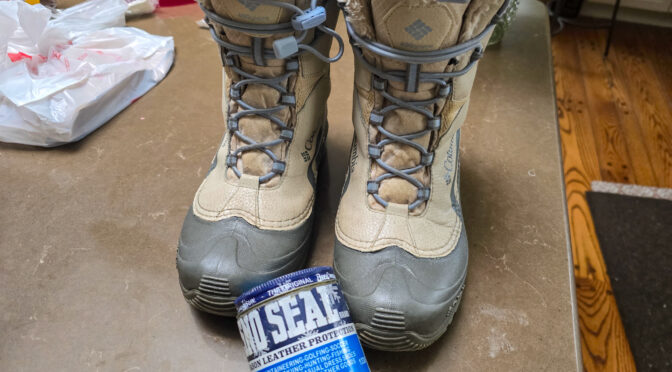
My youngest daughter told me her favorite winter boots were leaking. She’s long since grown and on her own so I told her to bring them the next time she visited and I would see what I could do.
She showed up a few weeks later with some nice winter boots made by Columbia that were a year or two old. As a kid growinmg up in Michigan in the 70s, we’d call this style “snow mobile” boots – but they were a rubber bottom, fabric upper and then had a felt liner that you could pull out that seemed to always wear our first.
These new Columbia boots were far nicer with modern materials but they were leaking. My daughter said the bottoms of her feet would get wet. I took a quick look and the rubber bottoms were in very good shape and so were the uppers. This left the most likely culprit to be the stitching where the uppers are sewed to the rubber lowers.
I actually like working on boots. Don’t ask me why – it’s just one of my thousands of personality quirks. I used to take my dad’s old leather work boots, remove the leather thongs, clean then and then make them soft and water proof using mink oil. For a while we had this cool stuff called “bear grease” that was wax and some oil that worked pretty well. At any rate, rather than drying out and cracking, not to mention leaking real bad, you could really streatch the life of your boots out.
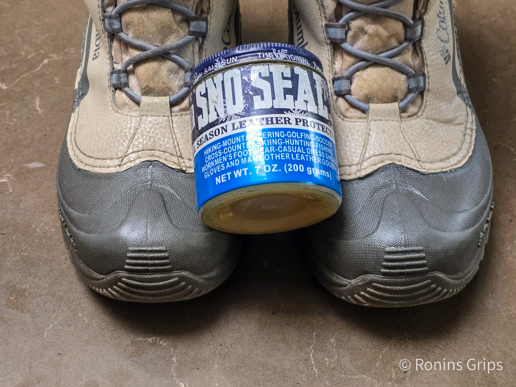
Many years ago, and I do mean “a lot” of years ago and any number would be a guess so maybe 20+ years ago, I heard about Atsko Sno-Seal. It’s basically beeswax and needs heat to really soak in. I’ve used it on more boot, tools and other uses than I can count. [Click here to buy it on Amazon]
To seal my daughter’s boots, I first warmed up the oven to 135F. That is the lowest setting of our oven and I didn’t want to harm her boots my getting the synthetics too hot. Once the oven was warm, I turned it off because otherwise the tops of the boots would be close to the heating elements and risk damage.
I then inserted her boots for about five minutes so they would get nice and warm. I pulled them out and pushed/rubbed a thick amount of wax into the seams. To be clear, I just did this on the seams – the uppers are synthetic and I didn’t want to risk discoloring them. I then put the boots back in the oven and let the wax melt and I would then rub in another thick batch of wax into the seams.
I repeated this three times. I wanted to make sure that any little openings, or “voids” in the seams were packed with wax. After the final heating, I removed the boots and wiped off the extra wax with a paper towel.
For the fabric parts of the upper and the tongue (the part under the laces in the front), I applied two coats of Scotch Guard Outdoor formula spray. I doubted the water was leaking in from these two places because of my daughter’s description that it was the bottom of her feet getting wet. However, since I had the boots, I figured I would do them also.
Note, ScotchGuard is a spray and is really easy to work with. I’d recommend you read their instructions first. I basically spray on a coat and let it dry then I do a second coat and let it dry. My wife hates the smell so I let them dry in my shop – so just bear that in mind if your spouse doesnt like chemical smells.
Applying Sno-seal to the seams took about 30 minutes. The ScotchGuard spray can be applied in less than a minute but the drying time depends on many factors – including temperature and if there is airflow from a fan. I usually let them sit and do other things.
Let me make one last comment – sealing boots isn’t a “do it one time and you’re set forever” activity. You might get a season or two and then you’ll probably need to do it again. Some guys treat it as part of their routine “getting ready for winter work” and some guys like me do it as needed or before some big outting like hunting, hiking, etc. Bottom line is that it works but needs to be maintained sooner or later.
If you do this and ever find yourself in a rush and don’t have Sno-Seal handy, you can try heating the seam up with a hair dryer and seeing if the remaining wax will seal the leak. This is a real gamble though as it depends on the amount of wax left. You could ideally seal the leak temporarily until you have time to do it right but you might also either accomplish nothing or even make the leak worse as the reamining wax moves and enlarges holes. So, it’s iffy and there’s no guarantee it will work.
Summary
The boots were sealed and my daughter was happy. I recommend Atsko Sno-Seal for a great many applications including sealing boot seams. The ScotchGuard Outdoor waterproofer works very well also.
I hope this helps you out.
Note, I have to buy all of my parts – nothing here was paid for by sponsors, etc. I do make a small amount if you click on an ad and buy something but that is it. You’re getting my real opinion on stuff.
I have a Harbor Freight 44991 mini mill that I bought it in 2006 if I recall right – it’s been so long that I don’t actually remember at this point. It’s served me well but like anything, stuff happens with age. In this case, the mini mill way covers were breaking down due to oxidation and repeated flexing.
I’ve replaced the way covers a few times over the years but this time had a challenge finding any in stock. In general, my goto spot for mini mill parts is LittleMachineShop.com and I recommend them to anyone with a mini mill or lathe. They’ve been out of stock for a while now and I wanted a solution sooner instead of later. I was adjusting my mill, cleaning it up in general and wanted to get the covers on so the ways would stay clean.
If you are new to machining, way covers aren’t just cosmetic. They keep debris off the ways (the machined surfaces that move on the X-Y table). If you don’t keep the ways clean you run the risk of something getting under the table and throwing it off or even just making cranking the handles harder.
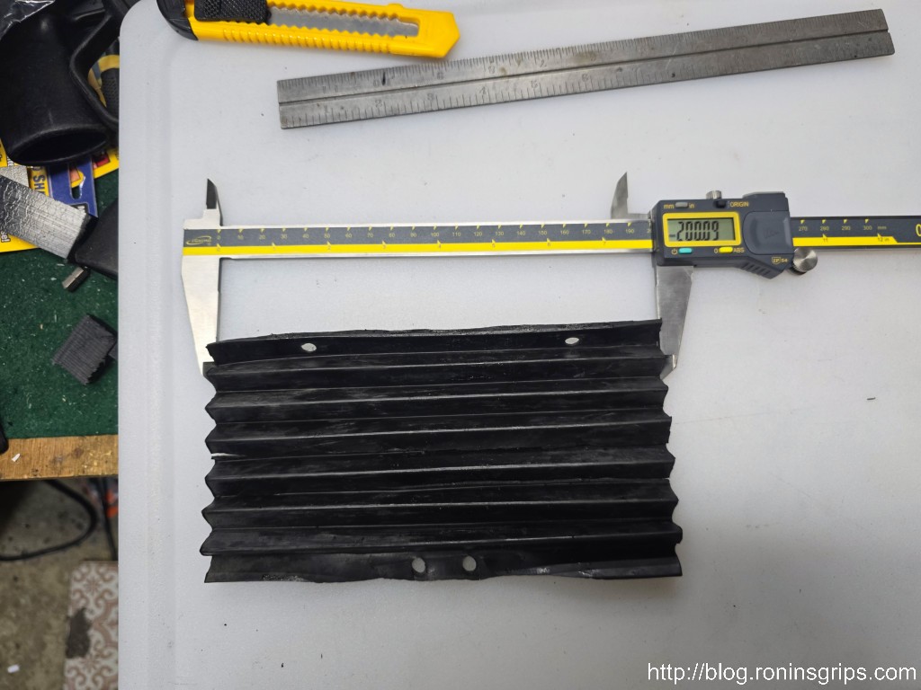
So, I needed to find another source but where? I had to figure out an alternative. Way covers have a diameter and length – how hard can it be if I searched using the measures and adapted whatever I found? The answer is that making your own is surprisingly easy. The way covers for the 44991 mini mill, and the two dozen or so brands that are actually the same machine made by Sieg in Shanghai, are 200mm wide and that’s the key – looking for millimeters vs. inches.
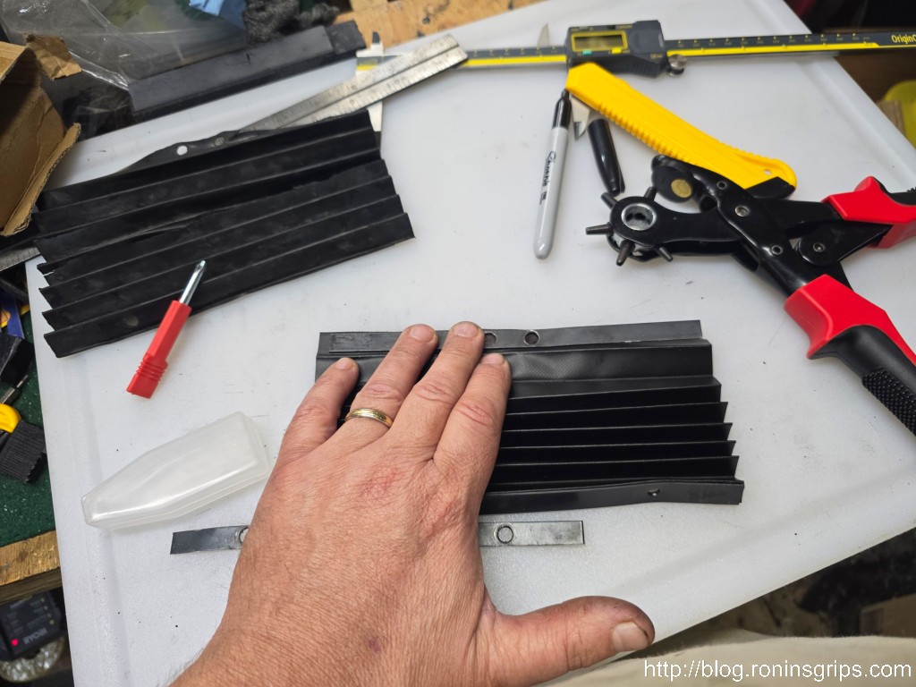
My initial mistake was to try and find a cover with a width between 7.75 and 8 inches. Then it dawned on me that the machine’s parts are actually metric and the width was 200mm. I figured if I could find a long enough length I would just cut it down and that strategy worked. By the way, that’s a 12″ IGaging Absolute Origin caliper. It’s a rare job where I need to measure something bigger than my 6″ Mitutoyo caliper can handle. For those rare occasions, the IGaging caliper has been good enough for me.
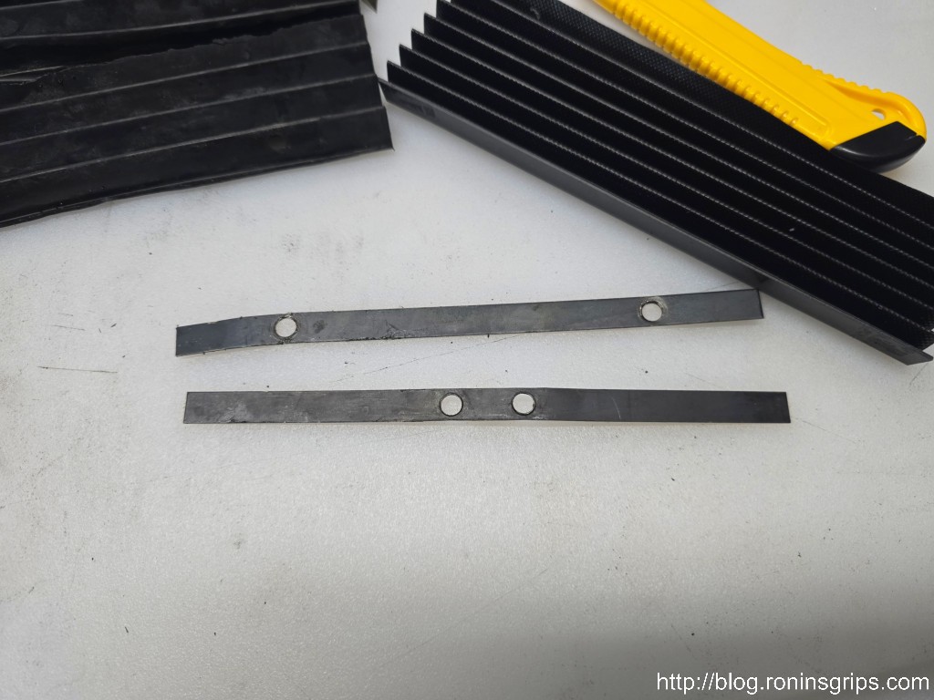
Armed with that, I immediately found way covers on Amazon. They are really long but you can cut them down with a plain sharp knife and straight edge no problem. Click here for the listing. At the time of purchase, they had one review. I was in a rush and figured I would gamble $10.19 not including a 5% off coupon. It was shipped from China and took about two weeks to arrive.
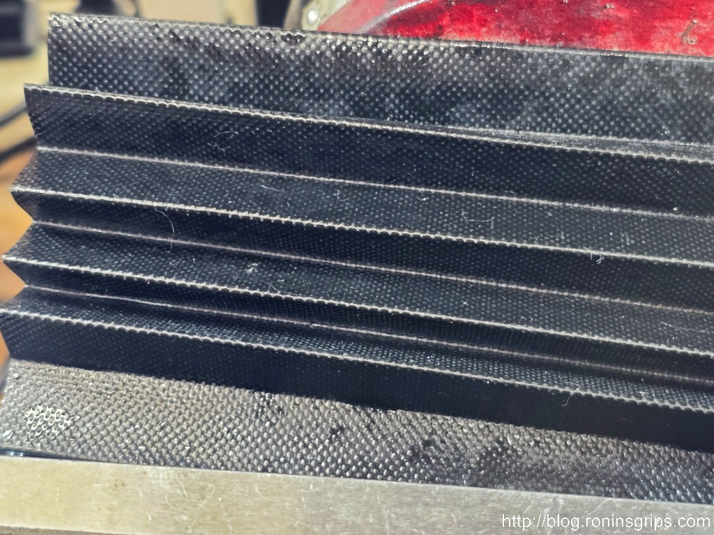
Guess what? They are actually really decent. Instead of rubber, these way covers are some kind of rubberised fabric. I’m not even sure rubber is the correct term and cutting them down to fit is fast and easy with plenty left over for a few more replacements (I stored the remainder in a heavy ziploc industrial bag and actually purged it with nitrogen. Yeah, I work with plastics so I have access to that stuff. Just sealing it in a good ziploc-type bag and keeping it safe would probably work too.
Let’s Step Through The Process
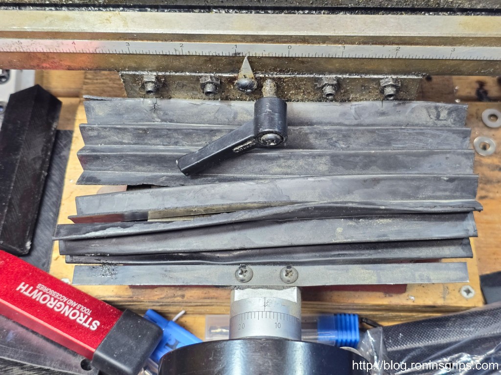
I did my covers one at a time starting with the front. The cover is held in place by a bracket on each end. Each bracket is held in place by two Phillips round head screws. Remove the brackets and the covers. Note the front cover has two sizes of screws when you go to reassemble it.
Each way cover is held in place by a metal strip and two Phillips round head metric screws. Note, on the front way the front and back screws are two different sizes so pay attention what goes where (the larger diameter screws are to the back if I recall correctly). This is either my second or third set of rubber way covers. They slowly break down with time and use.
With the cover off, I cleaned and lubed the ways and also the threaded rod. I then moved on to make the cover.
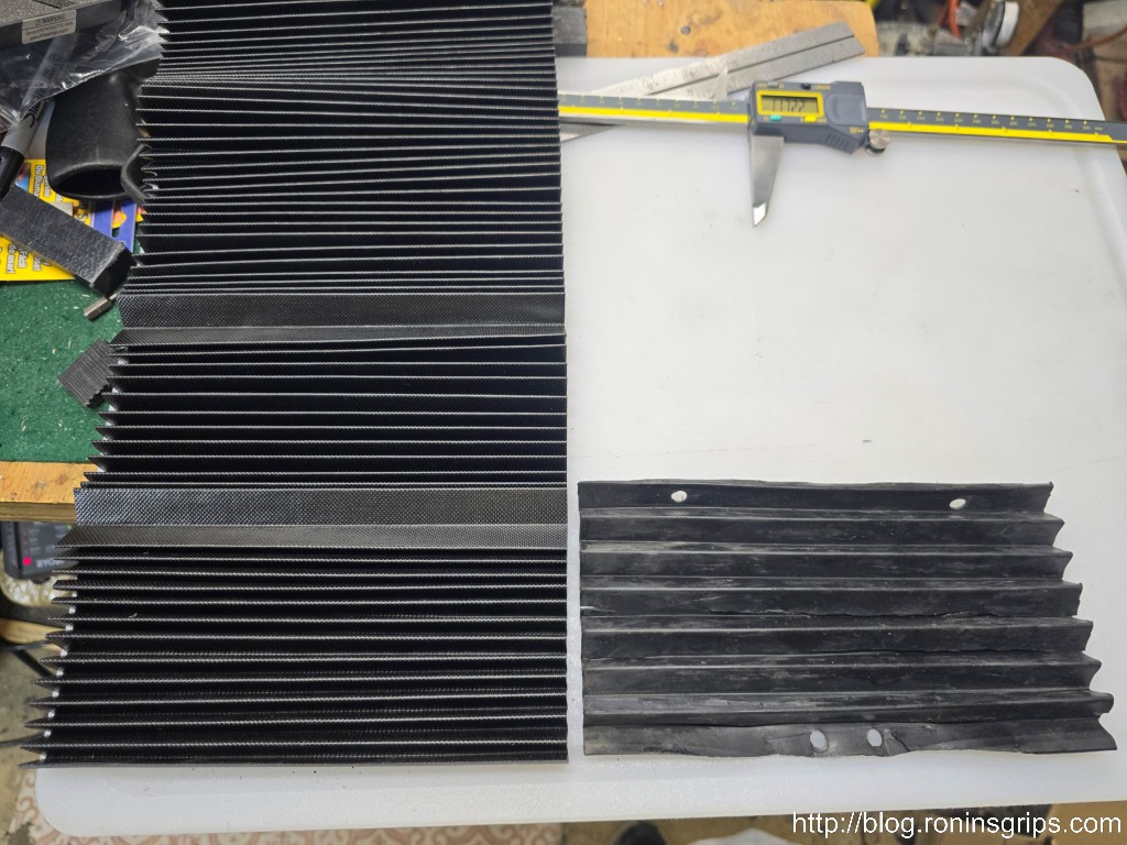
I removed the front cover and took the time to clean and lube the ways and threaded rod.The old way cover is to the right. The 200mm x 1500mm new way cover is to the left. It turns out the folds are 1.5cm on both so I just counted the peaks and made my cut. If the fold height didn’t match then I would have fit it based on the smoothed out length.I cut the length of new cover I needed and then used the old brackets to mark the hole locations.I marked the holes and then used a revolving hole punch plier to approximate the openings. I actually own a hole punch set but I don’t know where I put it – that would have been more elegant than my nibbling around the circle with the pliers but I got the job done.
I then did the same for the back and installed the way covers on the mini mill. The next time I do them, I may glue a plastic strip on each end to make it a tad more secure at each end but what I have is working great.
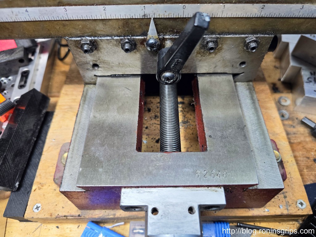
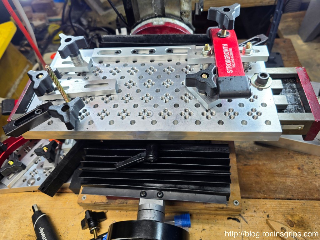
Looks much, much better and the ways are once again protected. It’s a tad floppy at the ends and next time I will add either a small steel or plastic strip the full width of the cover, scuff both sides for a good grip and join them with Starbond black super glue. The cover is perfectly serviceable as-is for now but am keeping that in mind for the future. By the way, that is a Dayton CNC 12″ workholding plate. I have two of them and they’re great. Here’s the link and the wait time is about 2-4 weeks. The positioning strips are from a vendor called Bulk Man 3D on AliExpress. All the holes and fasteners are 1/4-20 and the metric strips can accomodate 1/4-20 socket head screws in case you are wondering.I’m not sure what this material is but have a suspicion it will hold up better than the rubber. Time, use and exposure to lubricants will tell though. I’ve only had them on for over a week but cutting oil and penetrating oil don’t appear to have affected the material thus far.
Summary
The new way covers are working great. You can make your own and have plenty left over for the next time plus it is cheaper regardless. I have no problem recommending you buy this way cover and cut it to fit. I do suspect it will hold up better than rubber given it is fabric reinforced and not just plain rubber and we’ll see if that proves to be true.
I hope this helps you out.
Note, I have to buy all of my parts – nothing here was paid for by sponsors, etc. I do make a small amount if you click on an ad and buy something but that is it. You’re getting my real opinion on stuff.
Have you ever needed to use a nylon soft-sided rifle or pistol case only to find a seam is pulling apart? Yeah, that happened to me again the other day figured it would be a good time to share a trick with you.
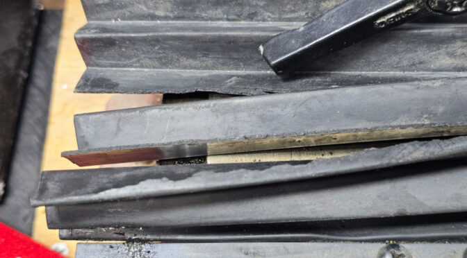
I re-use my cases and went to use a flat dark earth colored Midway rifle case only to find that a seam along an edge was pulling apart. Nylon is tricky – on one hand it is pretty strong and rot resistant but on the other, if you don’t pay close attention to what you are sewing and get to close to the edge or lack proper reinforcement, it can pull apart.
I bought two of these cases many, many years ago when Midway had a sale. How many years ago? So many that I have absolutely no idea how many – that’s the best I can tell you. Maybe 8-10+ years ago. The warranty was history long ago so I needed to fix the case. What I have found is that gluing the seam works wonders. The earlier you catch it the less obvious it is.
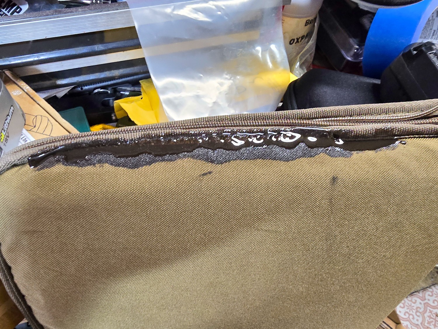
I didn’t think to take photos until part way into the repair. You need a glue that can bend and flex without snapping so any glue that dries, cures and is rigid will not work. I used Gear Aid’s Seam Grip WP have have also had very good luck with ShoeGoo. I am very impressed by Seam Grip and that is what I use the most. I’ll use the ShoeGoo too – don’t get me wrong and it works – it’s just that Seam Grip has become my go-to over the years. The one perk of Shoe Goo is that they have a black colored formulation.
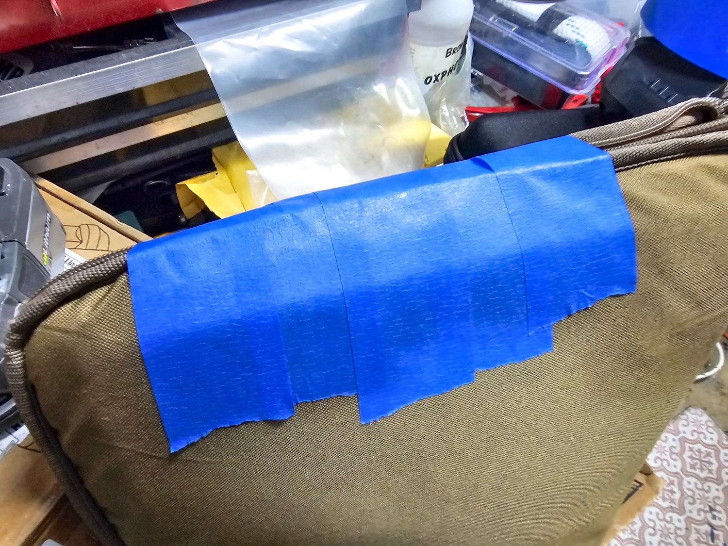
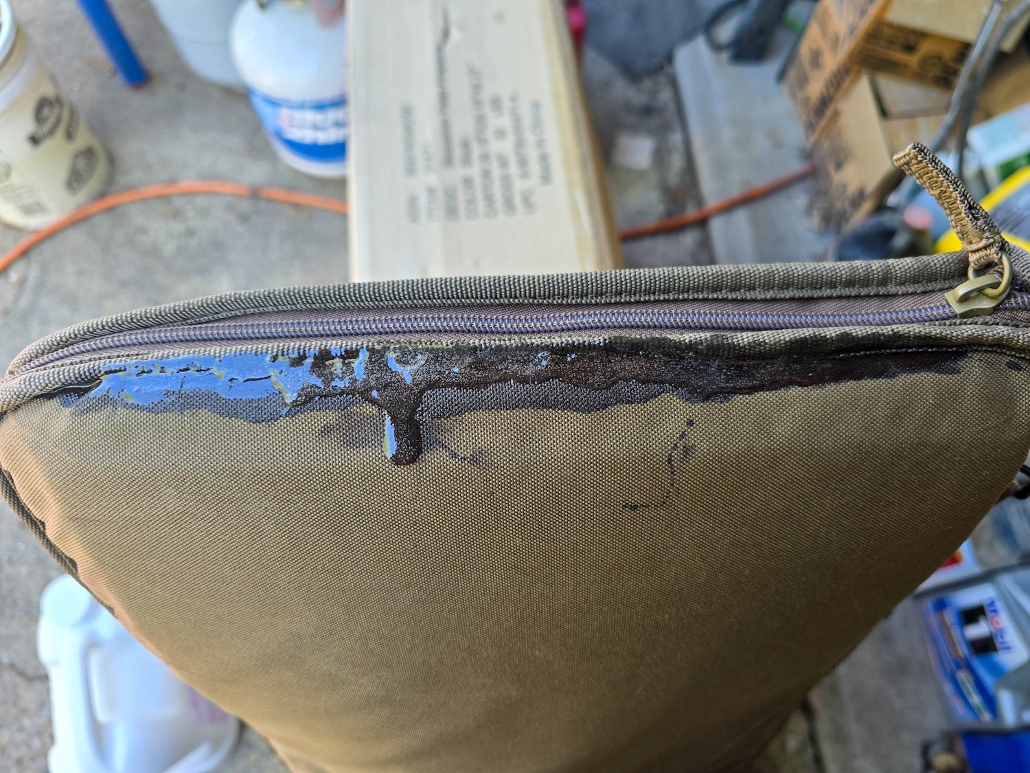
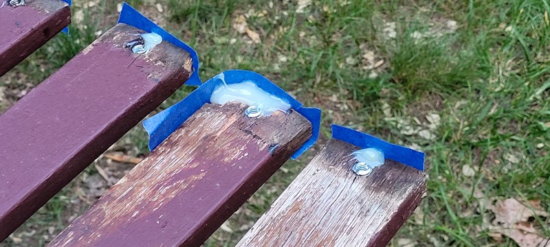
I find that doing 2-3 passes with the glue to work best. I work the first one in try to secure the nylon the way I want or at least get it close. When you do the repair, go a bit further in all directions to make sure the adhesive has a good solid hold.Use something to secure everything while the glue cures. I use blue painter’s tape here. I’ve also used clamps, rubber bands, you name it to hold things in position.Not all repairs go quite the way I planned. This was the third layer of the seam glue and I put it on thick to fill up a bit of a gap and it ran on me overnight. It may not look great but it’s good to go.
Summary
Using glue to repair a seam absolutely works, I’ve done it many times and never had it let go provided I get 2-3 good coats on it and overlap the hole. Follow the directions on whatever glue you do use as this repair will take 2-3 days to do as each coat cures. If you rush it, you risk not having a strong bond.
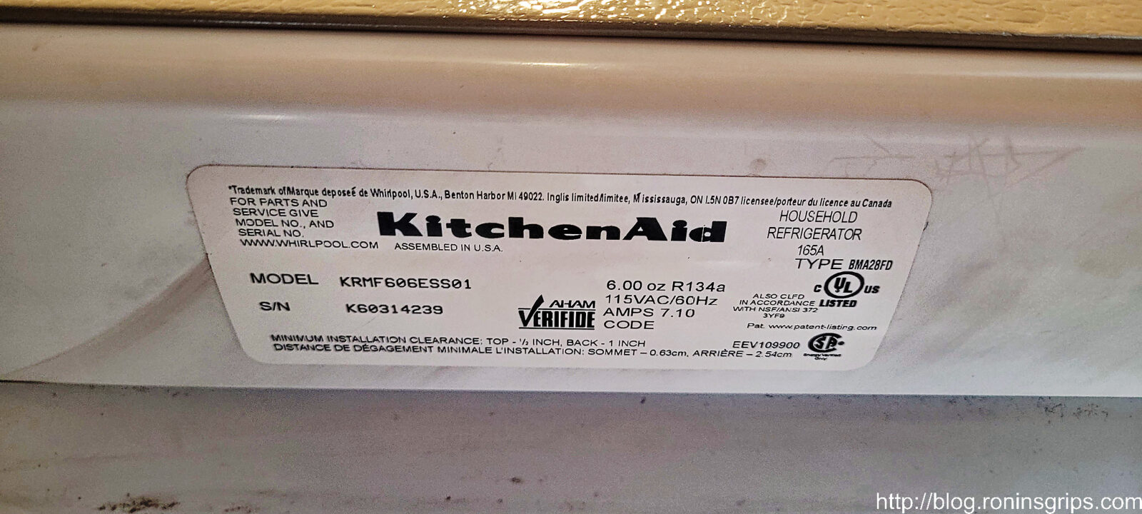
Well, when I was little it seemed like fridges (“refrigerators” for people who prefer the full word) lasted an eternity. When we bought this KitchenAid KRMF606ESS01, I thought I was buying a top of the line quality fridge, but that’s no longer the case – appliance manufacturers don’t necessarily want them to laste forever because that means no more sales to a given customer.
A year after the warranty the ice maker stopped working and the service person whom I trust told me it would cost a considerable amount of money to replace the circuit board. So, strike #1 against the KitchenAid. Despite being “stainless”, the shell of the fridge rusts. Strike #2. Strike #3 is the topic of today’s blog post. The water inlet valve failed and leaked water all over our wood floor.
Let me set the stage – I went through the kitchen to my shop and when I came back in I saw wet footprints – my foot prints – from the floormat in front of the fridge to my shop door. ARGH! I was hoping maybe someone spilled water and didn’t clean things up so I removed the mat, mopped up the water with a towel and watched new water slowly emerge from under the fridge. Crap. I immediately wondered about the water lines on and in the fridge. The supply line was copper tube and it had looked great the last time I pulled out the fridge so I doubted it was that but I couldn’t ignore it either or it would ruin our real wood plank floor.
Turning off the water
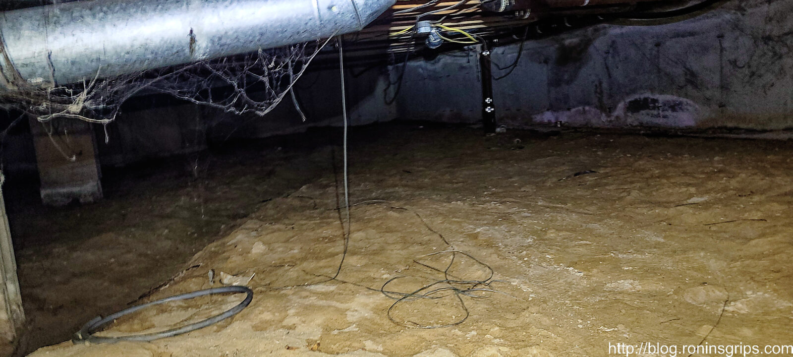
Most fridge installers put a vampire tap on a water line to get the supply needed. In my case, I knew there was a tap under the house. We have a crawl space that isn’t bad compared to some that look like they are a scene from a horror movie but being a pretty big guy with a sore back I have to fold myself in half and do a crab shuffle over to where it is about 50-60 feet from the entrance. Short translation – it’s doable but I swore the whole way over to it.
See that far center column in the dark? Yeah, I was heading just to the right of that and swearing the whole time. It was way easier getting under there 25 years ago.
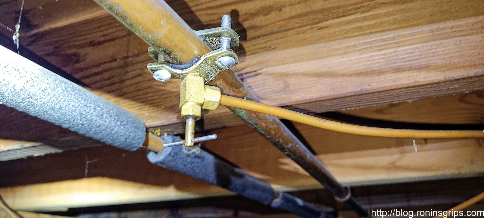
I don’t know if these things have a formal name – I’ve always heard them called “vampire taps”. They re put on copper supply like with a rubber gasket between the part of the saddle with the valve and the pipe. The two halves of the clamp are screwed together and then the handle is screwed down until the sharp end of the valve pierces the relatively soft copper. You then back the valve off (meaning turn it counter-clockwise) and water begins to flow through the supply line. So, with this in mind, I needed to close the valve which means turning the small handle you see clockwise until it stops thus closing the valve. I’ve needed pliers in the past to deal with hard turning valves and these things are also known to leak when you try to close them. I got lucky – it both turned easy and it shut the water off entirely just the way it should.
Confirming it was the inlet valve
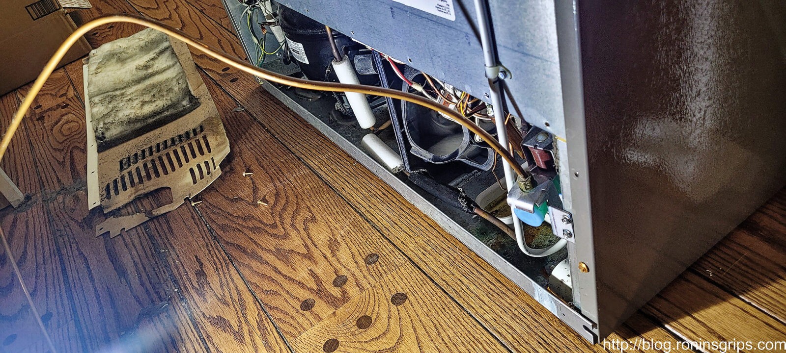
In reading, there are a few ways these inlet valves fail – they can leak water on the floor but still work and dispense water, not leak but dispense water very slowly, or don’t work at all. I was 90% sure it was the valve given past experience with other fridges so the first thing I did was to pull out the unit.
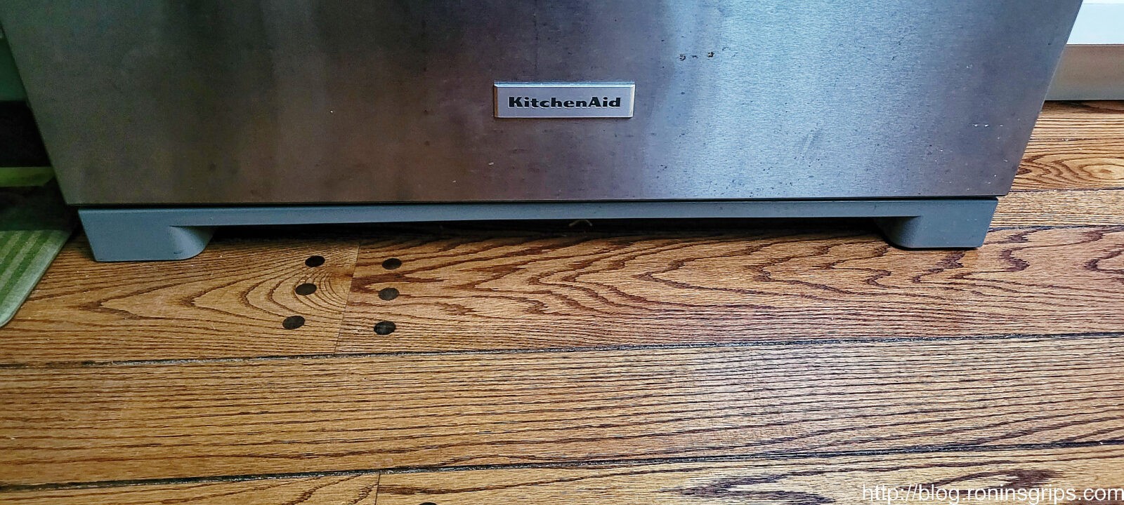
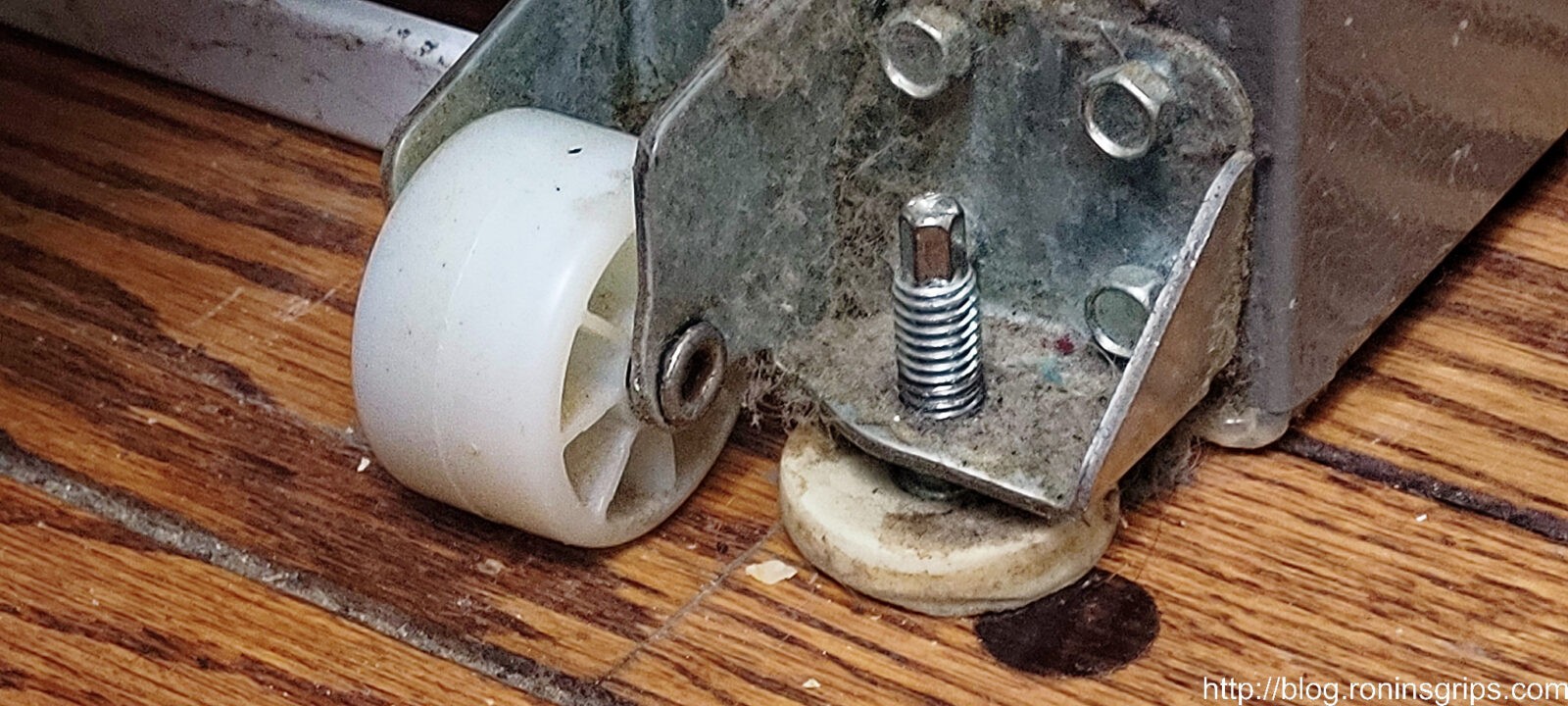
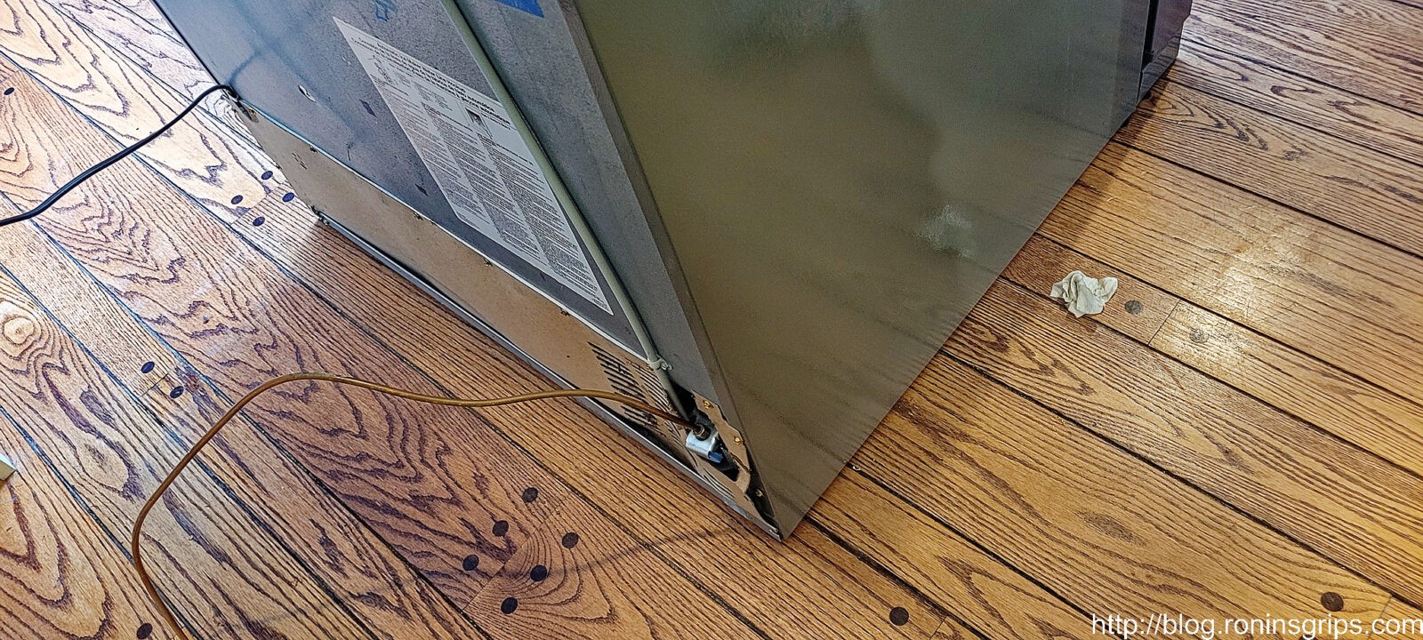
If you have never pulled your fridge out before, let’s start here. See the plastic facia/cover below the door? That is just for looks and pulls off but you need to open the lower freezer door to do so. Note the rust on the “stainless” steel skin above and to the right of the KitchenAid logo. “Stainless” is a generic term and really the resistance to corrosion is dependent on the alloy used. Whirlpool/KitchenAid went with a cheaper alloy to save money so it’s not very “stainless” over time.
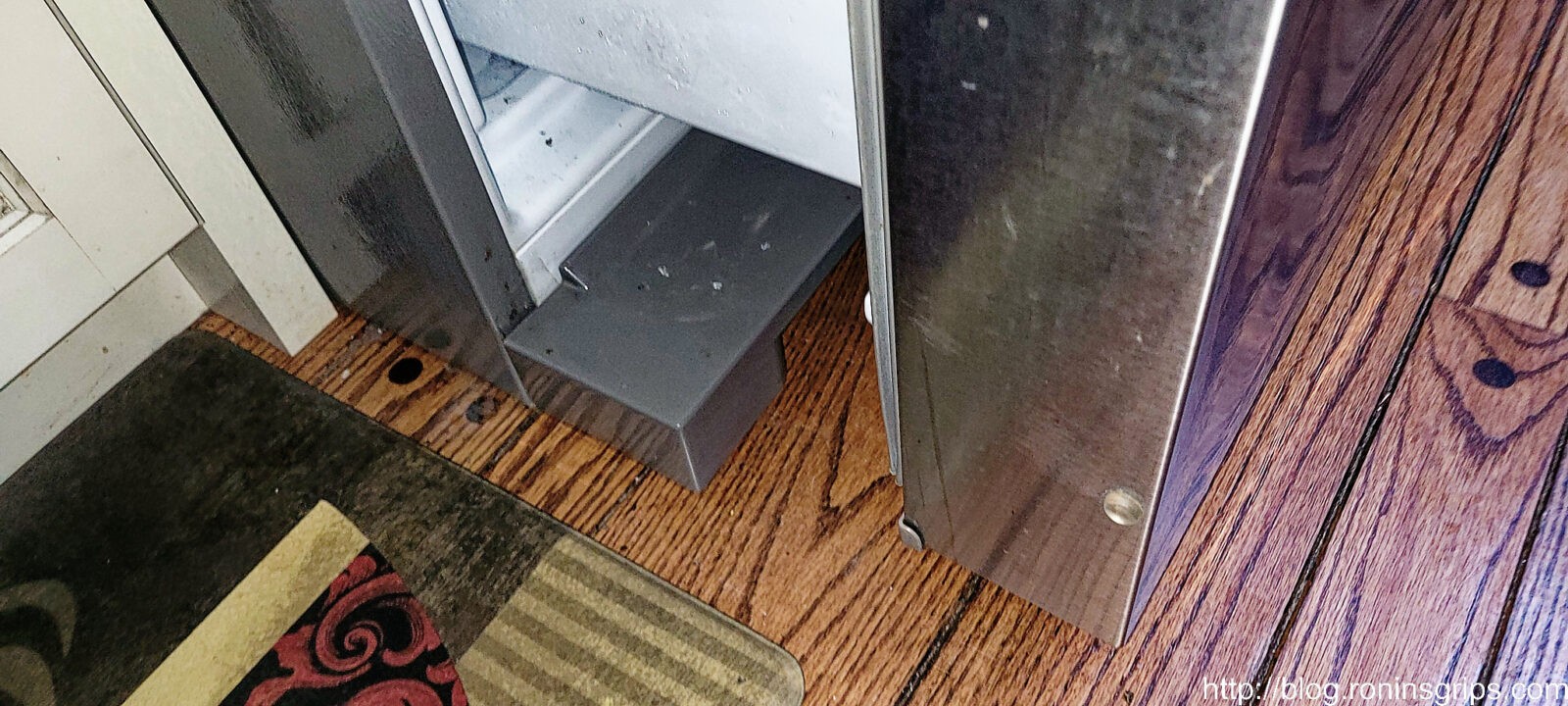
By pulling the freezer door open, the entire plastic covering is exposed and it literally just pulls forward – no screws or freaky little clips to deal with. They know folks will need to pull this off periodically (or they should) to clean the condenser coils under the unit. So, pull it off and completely remove it.
The fridge has four wheels to allow you to move it but if these small levelers are in use it will not want to move. Take a small wrench and turn the head of the bolt to retract the leveler on each side. The fridge will now pull forward. Peek in back to make sure you have enough water line to do so. The water supply line and the power cord will limit how far you can pull the unit out until you disconnect them – if you even need to. I never unplugged my fridge while working on it for example.
There was a real small chance that the supply line was loose so I tightened it just a tad and then hand my wife watch the valve for leaks as I went back under the house to turn the tap back on. It’s way easier and cleaner to do it with two people. So, I turned it on and she called down that water was going on the floor and I shut it off. The water started right under the valve and everything else was dry … my money was on the inlet valve was the culprit and it was.
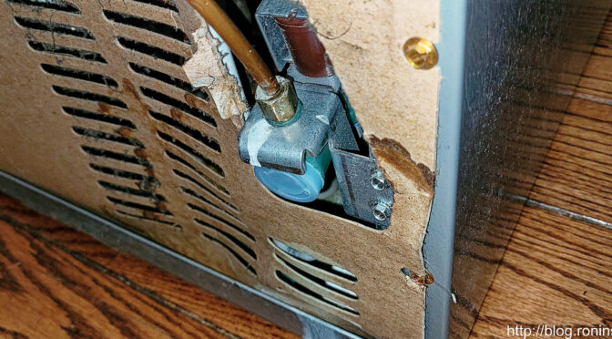
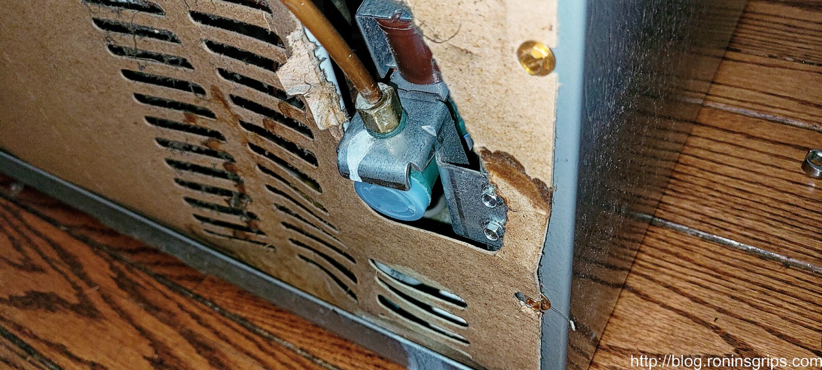
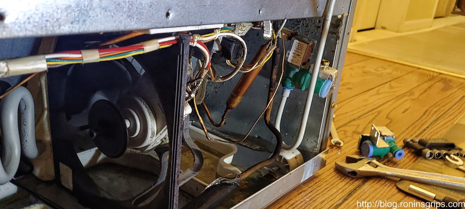
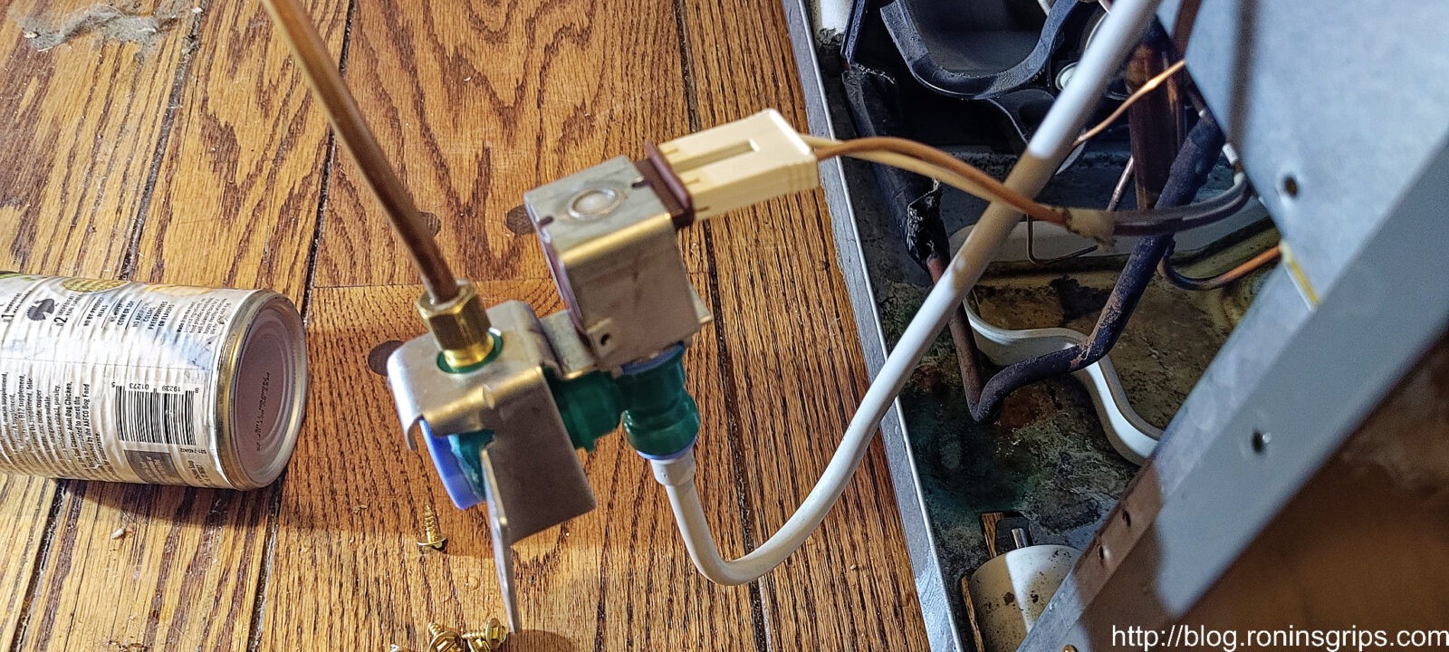
Okay, the water inlet valve is a small electricslly controlled valve that is turned on and off by either the ice maker (that no longer works) or a person wanting cold water from the dispenser pushing their cup against the on-off switch. The valve body is made of plastic and that is what failed. The only saving grace is that the engineers put it at the back of the fridge and it is very easy to access and change – literally a 5-10 minute job. You can easily buy one online without spending a fortune.
To order parts for your fridge, you need to know the exact model number – in my case it was a KRMF606ESS01. You can find this info inside your fridge – in my case this sticker was on the inside top left of the unit facing down hence the camera angle is looking up.
I spent some time searching on Kitchen aid KRMF606ES01 water valve and found out that my fridge has two – one at the inlet (that I needed) and one inside that I did not so make sure you order the right part. The valve part number I needed was W10394076.
Direct from KitchenAid I could get the part for over $95.49. No, Whirlpool, I didn’t feel like spending a fortune by ordering it direct. I kept on searching and found it in the $70s then the $50s and then hopped over to Amazon and found it for $27.99 with free Prime shipping. It got great reviews and I ordered it on Saturday with delivery on Monday. Guess what – it was the exact same valve. Strike #4 for KitchenAid by the way.
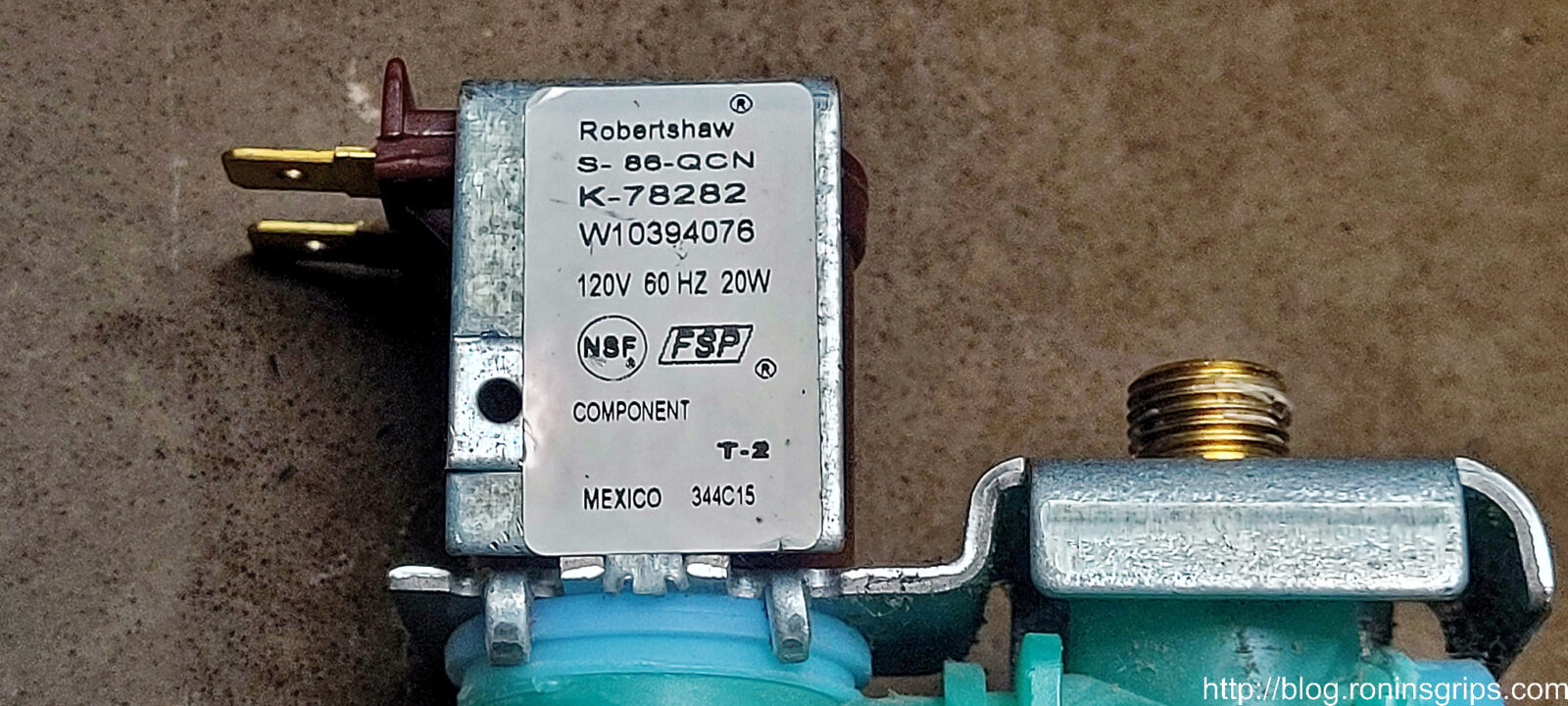
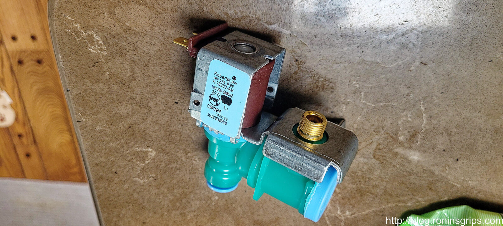
I’m jumping the gun a bit but this is the sticker on the original that I removed from the fridge. Note the maker is Robertshaw and their part number was K-78282 with Whirlpool’s W1039476 part number indicated.
First, make sure the water supply is turned off and have a container you can set the supply line in just in case it drops. I’ll step through this with photos:
get the the fiberboard back cover out of the way by removing the screws around the edges. Doing this gives you easier access and you can make sure there are no drips when you are done.
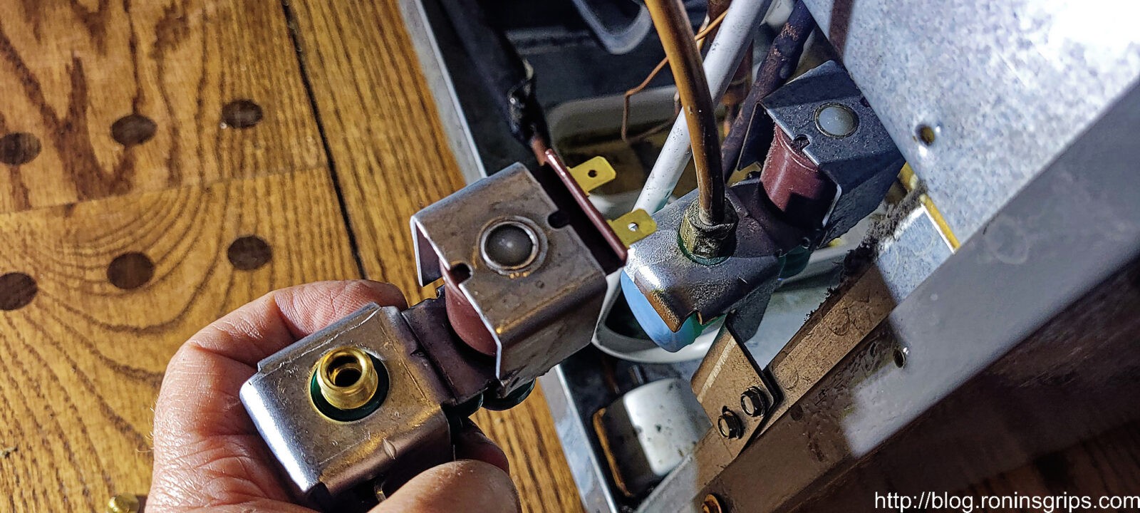
Always compare new and old parts to make sure they match. I have been burned so many times over the years that this comparison is automatic for me now – don’t assume anything.
I’d recommend moving connections one by one. Take one off the old valve and put them on the new one. Then again, you have three very different connections so mixing them up would be next to impossible. Do note the orientation of the electric connection and keep it the same. In this case, I am using the adjustable wrench to hold the steel bracket and a flare nut wrench to loosen the water supply line. Never use an adjustable wrench on flare nuts – if the jaws give you can round over the nut so at least use a fixed wrench or better yet a flare nut wrench.
The waterline in the bottom is connected via a “push-to-connect” or “push connect” ,fitting. Push the blue collar in towards the valve body while pulling the outlet water line away and it will come right out. Note where the white electrical wire is for reference. Looking at the valve from the back, it is on the left side.
This is everything moved to the new valve. I then put it in place and secured it with the original screws. Again, note where the white wire is at. I didn’t want to find out if it mattered which side was connected so I just followed the same wiring orientation on the new valve, Also, use the adjustable wrench to hold the valve body while tightening the flare nut.
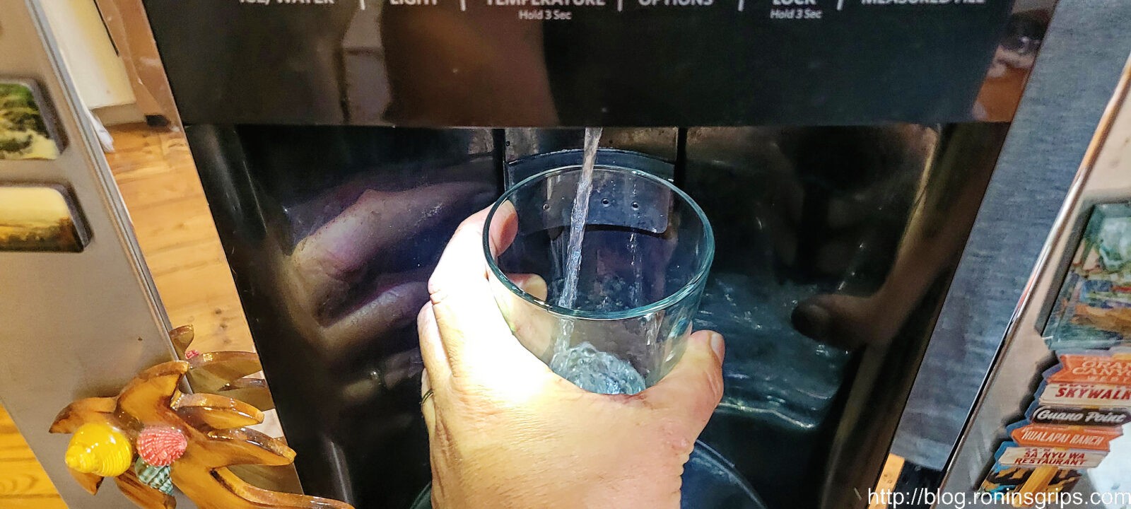
And with the new valve unit installed and my wife watching everything, I headed back down into the crawl space and turned the water on. No leaks. She tried the water dispenser and it was actually putting out a larger volume of water also – our jet had always been on the anemic side.
So, I waited while she filled a few big cups of water and threw them out to purge the lines. She also didn’t see any leaks so I headed back up after a few minutes hoping my crawl space work was done … and it was.
I looked for myself and it was definitely a much stronger jet of water – it had never moved that much water.
After a half hour of careful monitoring for leaks, I sealed it back up. I then waited a few hours and double checked by moving it forward a tad and checking around underneath with a flashlight and no leaks so I slid it back in place. When you slide it back, make sure the power cord and water supply line do not get caught on anything.
With the fridge back in place, use the levelers if you need to – I don’t actually.
I didn’t get photos but the last thing I did was to use a long brush made for cleaning condenser coils to do just that. As lint and dust build up on the condenser it becomes less efficient, the fridge runs more and your electric bill is higher. The lint and dust there by the way because of an electric fan that is running underneath to help cool things off.
The last step is to open the lower freezer door and push the plastic cover back on the bottom. Done.
I paid a premium for a supposed top-of-the line KitchenAid fridge and I don’t think the same level of quality is there. We have a Samsung fridge downstairs that has been flawless for us. When we replace this main fridge in the kitchen it may very well be a Samsung but it will not be a KitchenAid.
In the mean time, if you are having problems with your water inlet valve, I hope this helps you solve your problems and save some money.
3/2/24 Update: The new valve is still working great. We noticed we have more flow also – glasses fill faster. So, if you want to save some money, it’s an easy DIY repair that valve is still only $27.99 off Amazon.
Have you ever had wood that is in tough shape or is too soft to work with? A quick fix is to use super glue on the wood and let it set. Let’s talk about this for a minute.
Super glue is actually a family of glues called “Cyanoacrylates“. The patent for the original product goes back to 1942 when BF Goodrich was looking for a clear adhesive for gun sights in WWII. As they say, the rest is history.
There are many different brands and types of super glue. For the brand, I stick with name brand and usually get biggger bottles from firms such as Bob Smith Inc (BSI), Starbond, Loctite, Gorilla Glue, etc. With the no-name generics, you never quite know what is really in the formula or how good it is.
The glues are available in different viscocities/thicknesses also ranging from Super thin to normal, to gel, etc. For our purposes, we want th thinnest glue we can buy. Why? Because it will really soak into the wood and follow all of the little cracks that are opening, seal and reinforce them.
So, when I say I am using it to seal and stabilize, what do I mean? To seal means that water can’t get in. To stabilize means it is soaking into the soft wood, filling small cracks and when it dries it will harden the treated area. I’ve used this to fill small cracks in wood rifle stocks, knife handles, tools, furniture – anything with wood.
Super Glue is good for stabilizing but not filling an area. If you need to build something up, fill in a gap, or rebuild an area, then use an epoxy.
These slats bench slats had chunks of wood missing that I built up using epoxy. I sanded them down flush and then applied two coats of thin CA glue to the surrounding wood to stabilize it. I then used an opaqe wood deck stain and you couldn’t even see the repairs.
I apply several coats. The first one I apply quite a bit of glue and just let it keep soaking in. You’ll see it following cracks and what not. Once I get the surface soaked, I stop and let it cure. I typically wil do 2-3 coats/applications depending on how bad the wood looks. Usually after the second coat everything is sealed stabilized.
As it cures you will see a light white-ish smoke. Don’t get the fumes in your eyes or it really stings – you don’t want to breath them either. Small pieces like a knife handle aren’t too bad. For pieces bigger than that, all of the fumes really make this something you either want to do outside or in a room with really good ventilation.
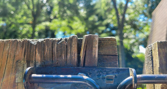
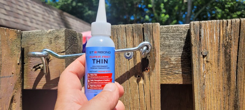
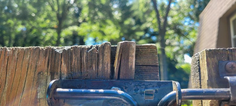
Let me show you a few photos form a recent project where I needed ro reinforce the area around a wood gate latch. The wood was in really tough shape and I didn’t have the time to go to buy the lumber, cut it and make a new one. I keep thin super glue in stock at all times for all kinds of projects so I just did that
Starbond makes good CA glues from my experience. I’ve used a number of their forumlas and been happy with the results. As you can see, the wood is in tough shape. It probably should be replaced but I don’t have the time.
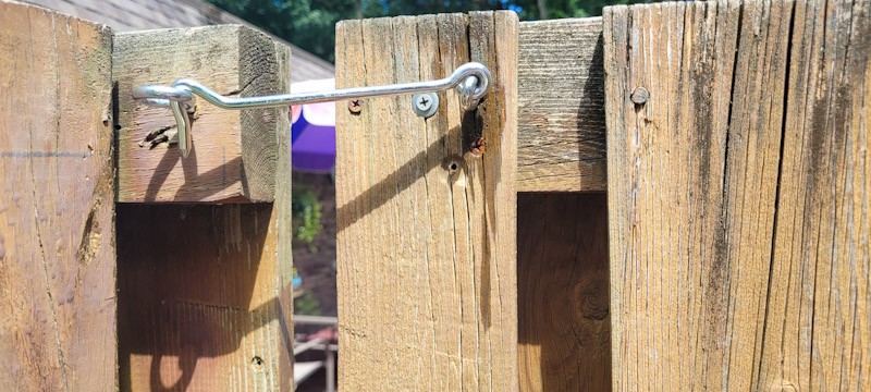
I let gravity work with me and apply the glue to the top of the wood and let it soak into the end grain. I could see it going down the board and the wood looking wet where it travelled. You’ll use a fair amount of glue doing this, I went across the entire top of that board and watched for the glue to penetrate – in this case I wanted it down near the screws. When it the glue cures, the stabilized wood will still a bit darker than the surrounding untreated areas.
This board was in really tough shape. It soaked in a lot of glue and I kept adding it until I saw it saw it in that big crack.
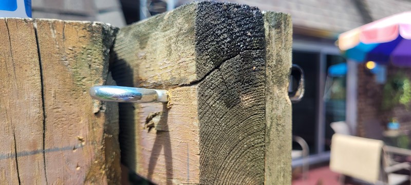
Here, the CA can help seal the top and stop the small cracks but there is no way it can fill the big crack.
Have you ever been stuck between a rock and a hard place because you need to get something done but a vendor fumbles the ball … badly? That happened to me recently. We have a home made in the 70s and the pool is the same. While we have replaced the liner a number of times over the years, it was the original slowly falling apart diving board. We actually bought our home in 98 and the previous owner had put a 2x8x6 between the board and the spring to keep it alive.
Let’s fast forward to about a month ago. We were getting ready for a family reunion to be held at our place so I got the pool ready for the summer and decided I better check the diving board. Oh man, it was shot. The fiberglass underneath had torn around the board it encased and there was just no way it was safe.
One thing I have learned about pools over the years is that you can usually find parts. So, I new it was an 8′ residential diving board and the hole pattern for mounting it was 4.5″ on centers in the back and the front single hole was 36″. I did some digging and the hole pattern and distances from the back and sides corresponded with the SR Smith 8′ Frontier II board.
A number of vendors carried it online and the problem was that I needed it with only about a two week lead time before people started arriving for the party. InTheSwim said they had it and it would arrive in time. I used my wife’s card on the website and it wouldn’t go through so the website gave me an 800# to call. I did, the lady told me it was a fraud screen, I approved a text message sent to my wife’s phone and the InTheSwim operator told me it was all set and I should get an email shortly. She never said she resubmitted it … About an hour later, still no email so I called and I am pretty sure the same lady answered and said the order was fine …. in fact it was not.
After a week of no updates, I called and after confusion on their part, they found the order in limbo, fixed it and told me it would probably still make it in time. Okay… I kept tabs on it and finally called and said I needed the board. They told me it would not even ship until after the party. I asked that they expedite it, that I would even pay for it and they said they had no way to do that. I then told them in no uncertain terms to cancel the order. If that reads like a rant, it should. I hate it when a vendor fumbles the ball and literally does nothing to make it right.
I was left with two options – disappoint a bunch of relatives or figure out how to fix the board. I decided to do the latter and I suspect this is the part of the post you really care about.
What went wrong with the board?
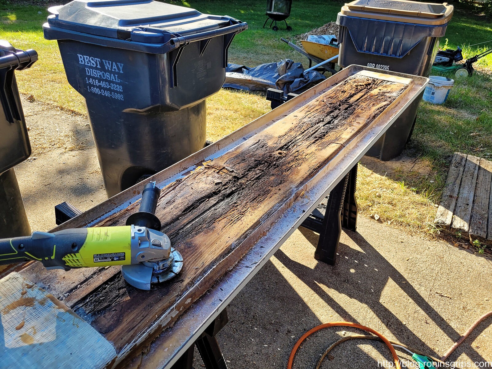
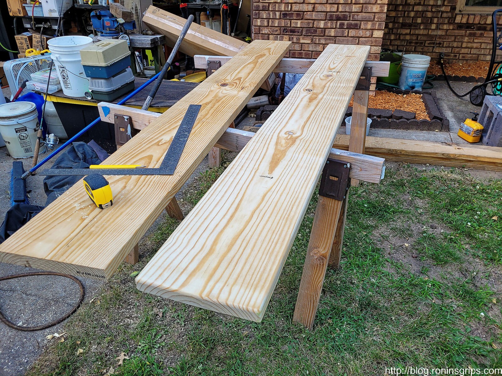
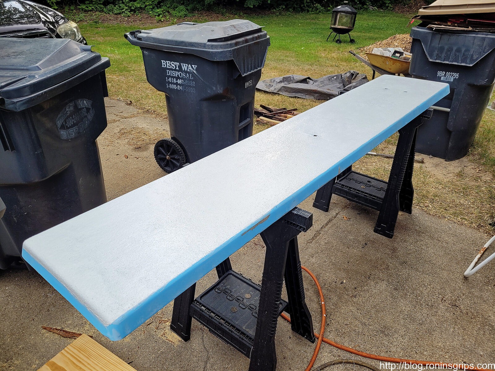
Many, if not most, residential diving boards have a fiberglass top, sides and bottom but the core is wood. Through the in the fiberglass rotting wood was plainly visible. I put the board on sawhorses, put the old supporting board underneath it and flipped the diving board over to access the bottom. Again, the diving board was resting on the old supporting board – I new that if I didn’t support it, the odds were high that it might snap. Once supported, I used a diamond masonry cutting wheel in my 4.5″ Ryobi cordless grinder to slice off the torn fiberglass to see what was going on. I had a hunch that If I could salvage the top of the board, I could fix the bottom and I was right.
Important Safety Comment: Wear eye protection and a quality face mask (N95 or better) when you are cutting or sanding on fiberglass. You don’t want stuff getting in your eyes or lungs. I also wear gloves to protect my hands.
I used a masonry cut off wheel – in this case a diamond coated one – because the glass fibers can dull saw blades, etc. Just about anything can cut open fiberglass – it just depends on whether you care about what is happening to the blade.
Once I cut open the bottom that held the wood, I could see it needed to be replaced. What was there were three pieces of wood and there was a cap on each end with nails that held it together. Over the years as holes and cracks opened up, water got in and slowly rotted the wood. I really wasn’t surprised when I went to lift the board off the spring – it weighed a ton due to the waterlogged wood.
The wood wouldn’t lift right out so I would prop it up and cut it with a small hand held Ryobi circular saw into thirds. I used a small pry bar and lifted the sections out. I didn’t cut all of the fiberglass out yet thinking that I might use some of it to make things stronger. In hindsight, I’d now tell you to remove all of the hold fiberglass wrapping on the bottom -there was no need to save it.
Wood and Fiberglass
In a perfect world, I would have the exact same size of wood and better yet, treated wood, to replace the rotten wood. I didn’t have time for wet treated wood to dry so I went to Home Depot and bought two 2x12x8 pieces of dry pine lumber. One to go in the board and one to still support it even though it probably wasn’t needed.
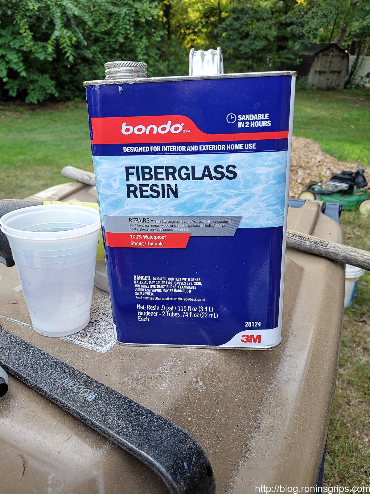
I also stopped by the adhesives section of Home Depot and picked up two 1-gallon jugs of Bondo fiberglass resin and three packages of fiberglass cloth – if I had it to do over, I would have bought a couple more for complete overkill in terms of strength. I knew I had a spare cloth at home so I had four fiberglass cloths total. I also bought a spare package of hardener just in case.
Here’s one of the jugs of resin. Because I work with plastics, I had a large selection of mixing cups and stir sticks. I used 32 oz cups and a half tube of hardener at a time. I would mix them and then pour the contents into a second 32oz cup. This is known as a double pour and reduces the odds of you pouring unmixed contents and making a mess.
Note: The Bondo fiberglass system uses a polyester resin vs. true epoxy. Polyester is cheaper than epoxy but not as strong. I’m pretty sure it will hold up and we’ll see over time. I’m writing this post a week after our reunion and the board looks just fine – no cracks.
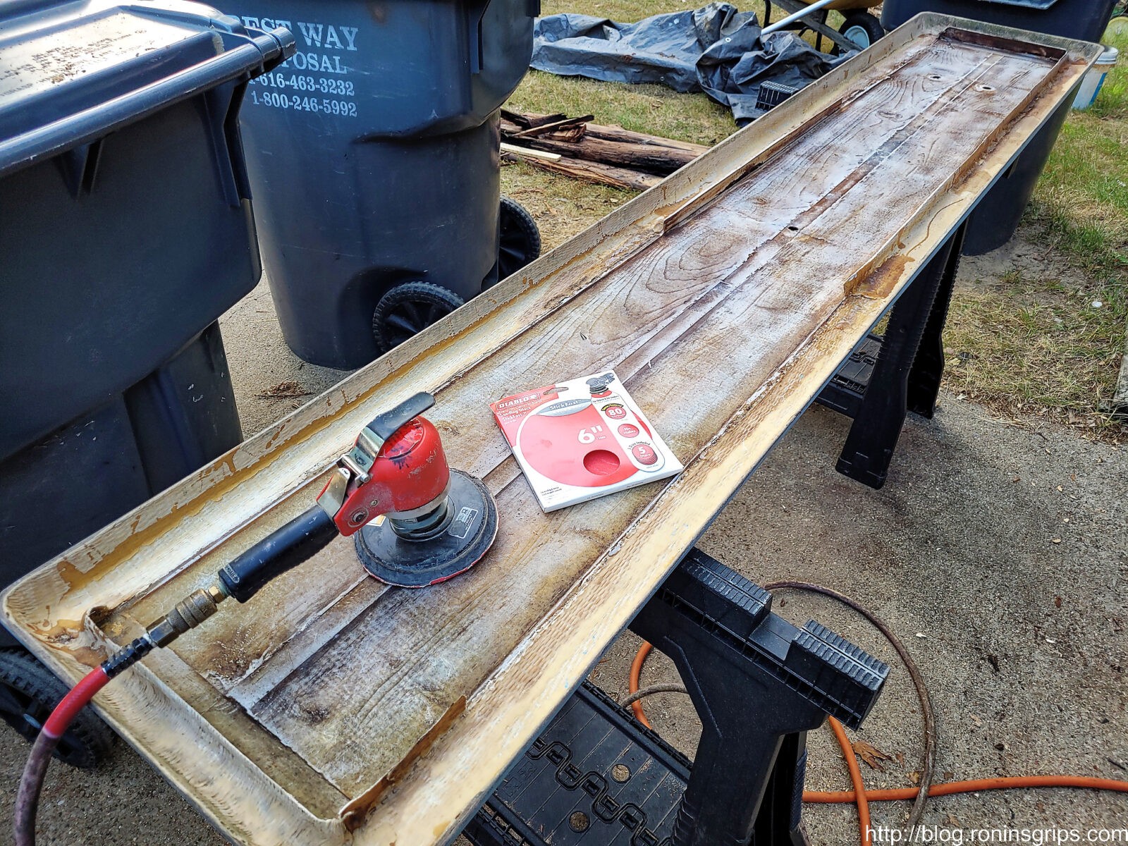
Cleaning Up The Board and Preparing It
With the wood out, I then removed all of the debris to get a better look at what was going on. I removed almost all of the old fiberglass that was holding the old board – I now know I could have removed all of it.
Here I am scuffing up everything really good with 80 grit sand paper in my orbital IR 6″ sander. If you want the fiberglass to bind really well, the surface must be abraded. Just remember, if the surface is smooth and shiny, your adhesion is going to be bad. A very abraded clean surface is ideal.
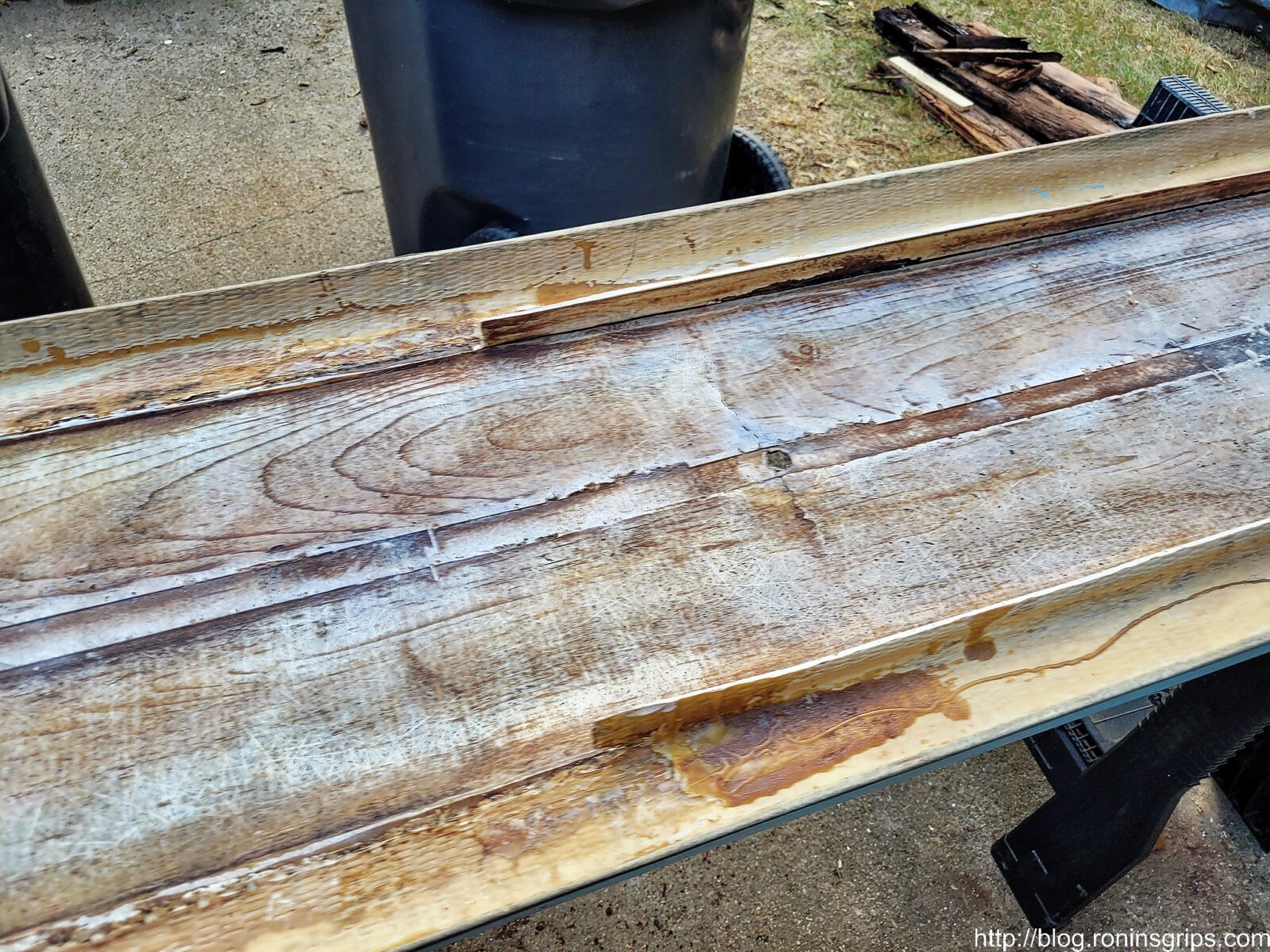
Here’s a better view of the center front hole and the big crack that went completely through the fiberglass top. Note, after sanding, cleaning and degreasing, I closed all holes with black Gorilla tape before I started apply resin. Once again, I would remove all the old fiberglass that surrounded the board. Those vertical pieces you see would be gone.
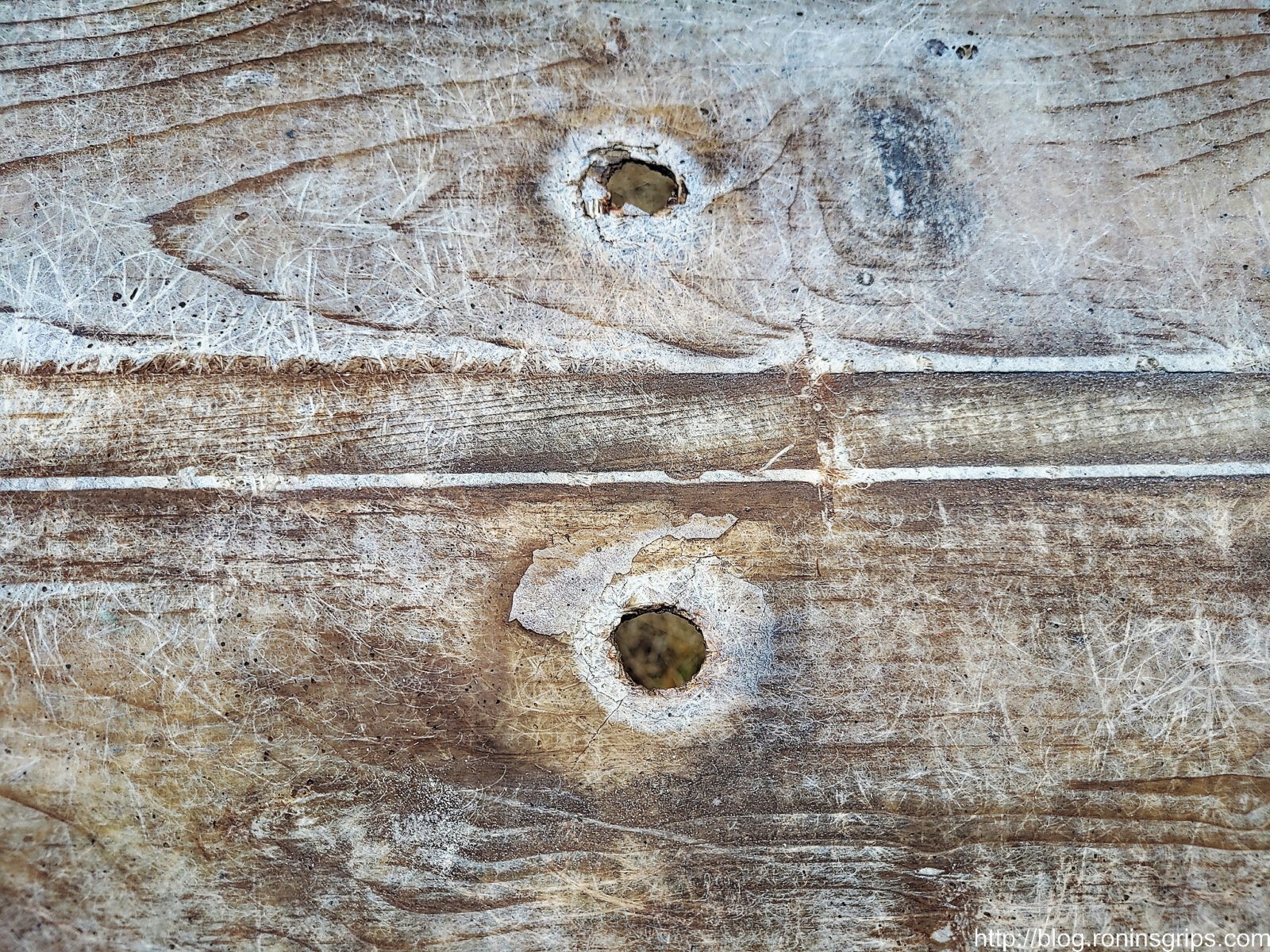
Here’s a close up of the back two holes – they are worn open and stress cracking around them.
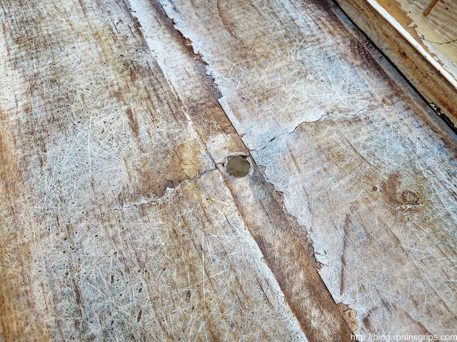
One more view of the big crack at the center. I sanded the heck out of everything with 80 grit, sprayed down the inside with brake cleaner thoroughly to degrease it and then stuck big pieces of gorilla tape over each hole. The diving board surface was ready.
Preparing The Wood
The wood was completely dry – let me stress that. If you seal in wet wood, it will rot so make sure your wood is dry.
One thing I noticed with the rotted wood that I pulled out was that they had rounded over all of the corners/edges of the wood to not stress the fiberglass. That made a lot of sense to me. I put a 3/8″ carbide tipped round over bit in my trim router and rounded over the new board too and then sanded it with 80 grit sandpaper to prepare the surface for maximum adhesion.
The 2x12x8 boards were longer than the original so I trimmed them down. I then used a round over bit on both and sanded them. My plan was to embed one in the fiberglass but still have a support/buddy board underneath. Note, I did not drill any holes. My plan was to center the new pine board insert and drill the holes later.
I did test fit everything before I went to the next step. You don’t want to mix up resin and get part way in only to find our boards are the wrong length.
Gluing The Board In Place
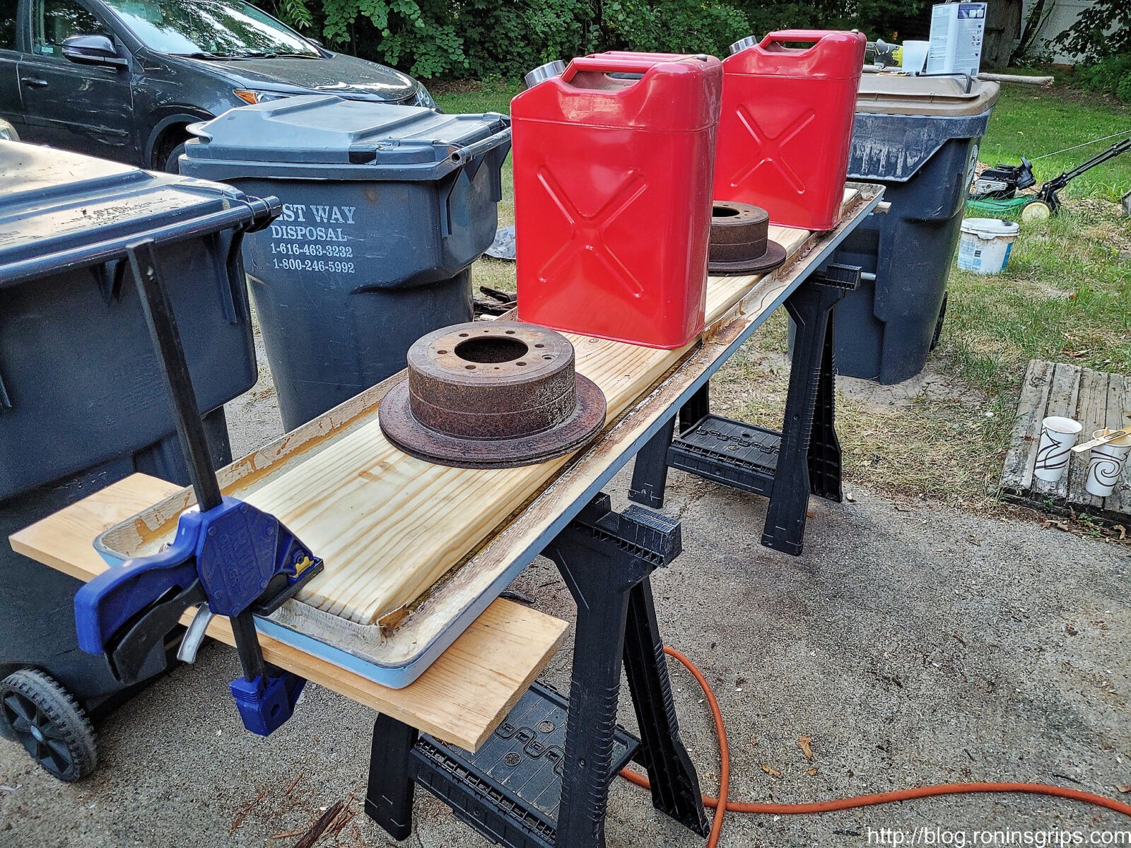
Okay, to close the bottom back up, I did it in steps. For the first one, I mixed up 32oz of resin, liberally brushed it in the bottom of the board really thick. I then clamped the ends and put weights in the middle to keep everything pushed together. You need to have this planned out because once the resin sets, it’s game over. I had the clamps and everything ready to go.
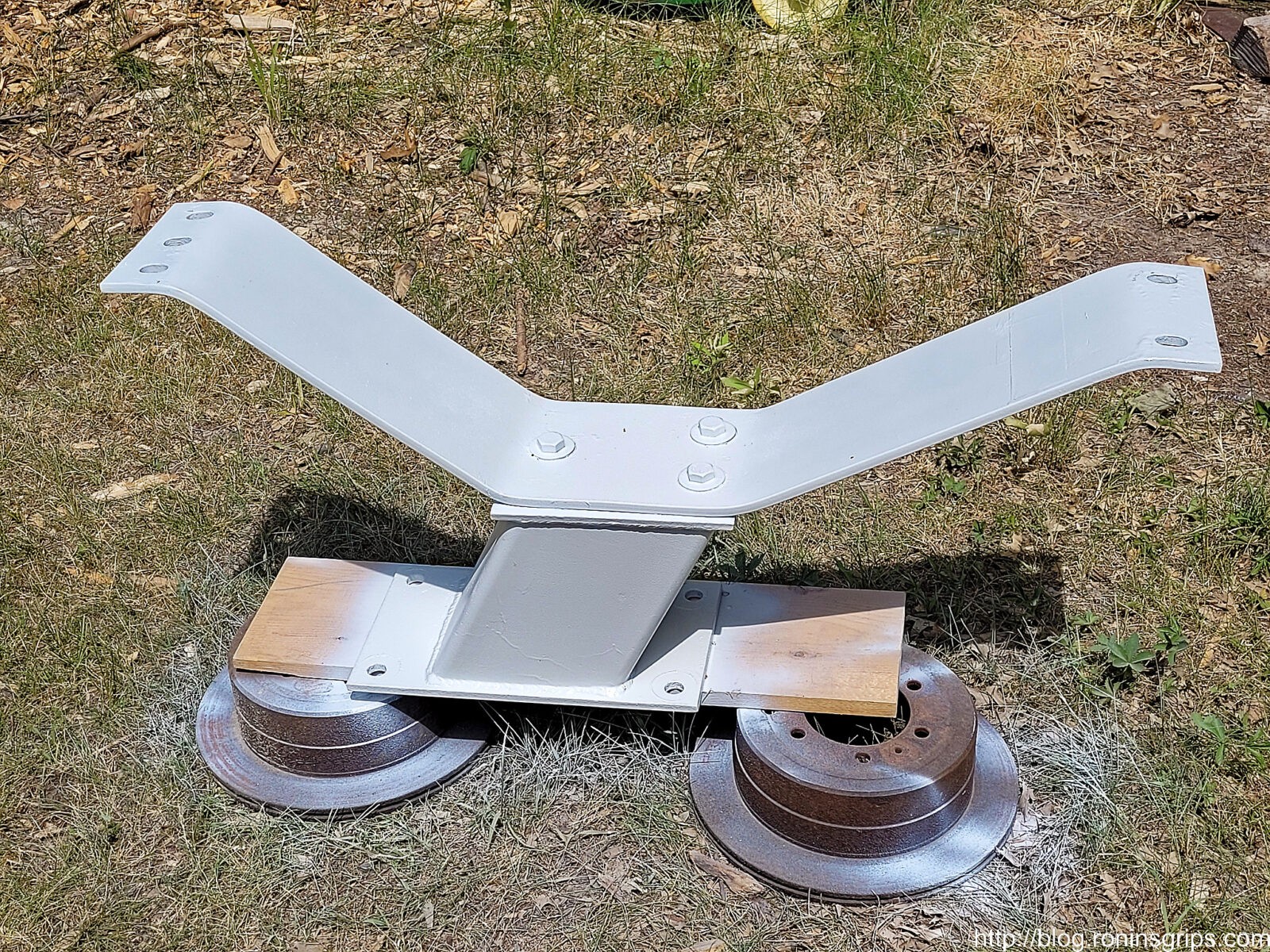
This falls under the “make do with what you have” category. The blue clamps are really strong and are on both ends. In the middle we have two brake calipers from a 96 Landcruiser and two full 5-gallon cans of gas. The more pressure pushing the parts together and the adhesive into as many spaces as possible is what you want.
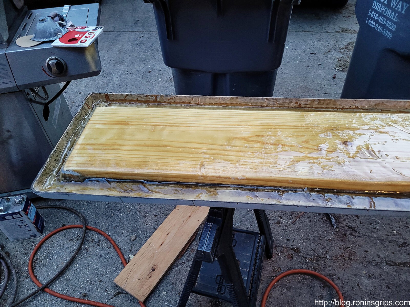
The next step was to put down the first layer of fiberglass cloth. I laid the cloth on top of the board and trimmed it to fit inside and just up the sides. I then mixed up a 32 oz container [don’t forget to do a double pour and use the right amount of hardener] and rapidly brushed it on very thick to the front area I was working on, applied the cloth and then another coat of Bondo on top. If you’ve not done fiberglass before, start with one section and learn. You want to get the cloth in place and wetted down with the liquid before it all sets. Also, have a bunch of nitrile gloves near by or you will get this stuff all over your hands no matter how hard you try. I wear gloves and have at it. I use my hands to rub the liquid into the cloth.
I did the front, the back and then the middle. If you need to stop, just sand the surface, blow it off and continue.
This is about the first half of the board. I let it cure and then sanded it before I applied more.
So I did the front, the back, then the middle. I used the full length of the cloths and overlapped at the middle. At this point, it was rock hard and I really wished I had just cut out all of the old fiberglass walls that surrounded the old wood. I thought it might make it stronger but then realized this wasn’t the case. I sanded again and cut my fourth and last cloth down the middle. I applied one length on the left and one on the right to strengthen those areas that still had the remnant walls that I should have removed.
Here it is with all of the layers applied. My next move was to sand and then paint it.
Drilled The Holes
Before painting, I flipped the board over, removed the Gorilla tape. The brownish color of the Bondo clearly showed me the old hole positions and drilled two 1/2″ holes in the rear and one in the front using the clearly visible filled in holes. I carefully pushed the support board under, clamped it in place and drilled it as well.
Painting The Board
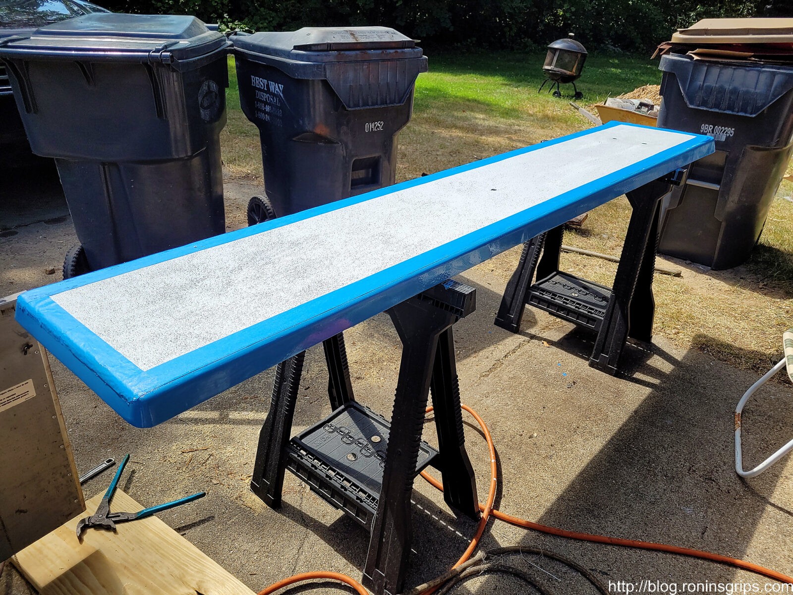
To paint the board whatever color you want, use boat paint – what they call the top coat or deck paint. Years and years ago, I painted our board because it looked really tough and found out you had to add non slip grit to the paint or people would slide off. Yeah, there’s a story there about a teenager falling off so make sure you get the non-slip additive for whatever paint you buy.
I used Rust-Oleum’s Topside White for the board and a Ocean Blue paint made by Pettit for the trim. The only reason I went with the Pettit paint was that the local boat store carried it and Lowes didn’t have the blue colored Topside paint.
So, when you are applying this, do it in a well ventilated area, make sure it isn’t going to rain if you are outside (I was in my driveway) and follow the guidance carefully. One thin coat a day. If you try and do a thick coat or too many coats, the paint will not cure to a hard finish and stay in an odd tacky/smudgy state. I had this happen to me years ago because I’m not patient but I sure hard to learn patience with some of the specialty paints.
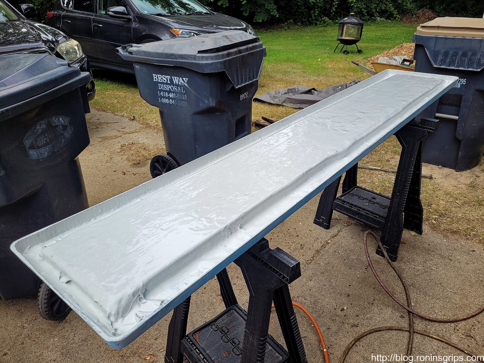
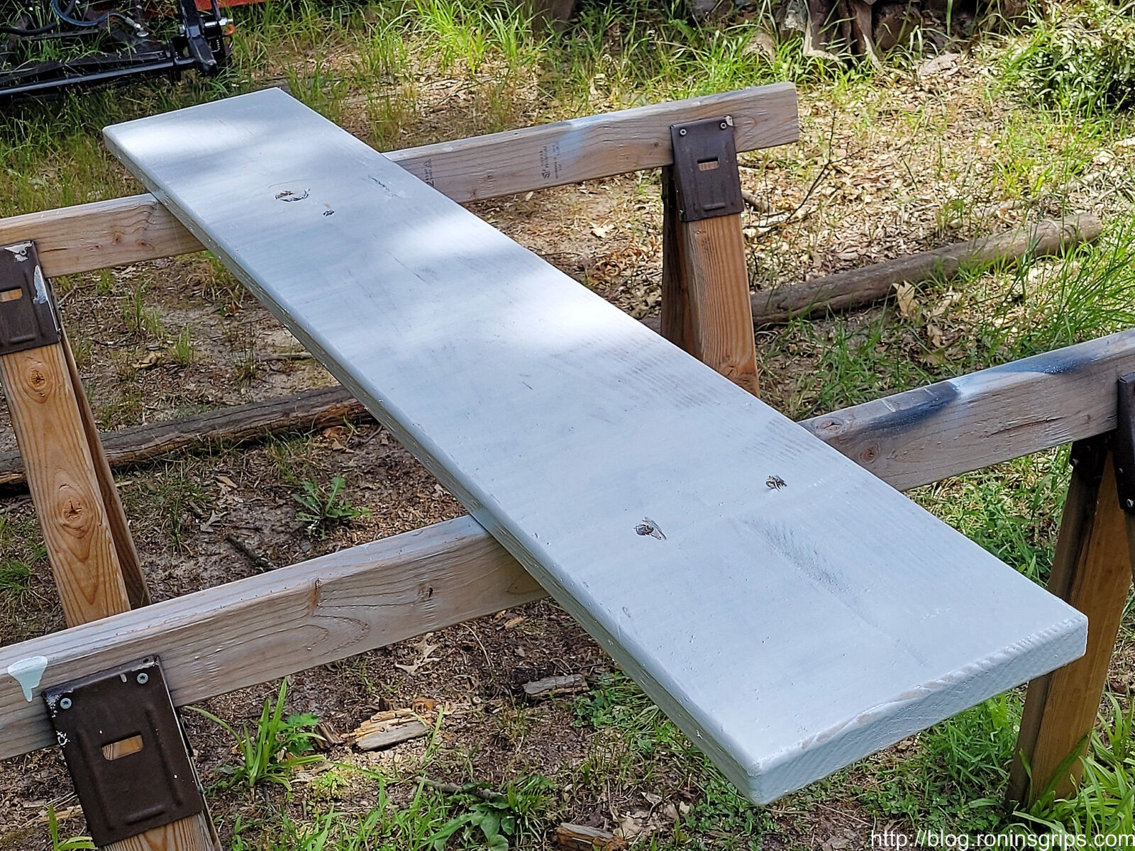
I did two coats of regular white Topside paint on the bottom to protect the fiberglass from UV rays (they really mess up plastics, epoxies and what not unless they are designed for them) and I applied two coats of the white with the grit mixed in on the top.
That’s two coats of white TopSide Paint on the bottom. I did NOT use the non-slip there.
I painted the top with the non-slip additive and didn’t worry about the old blue colored side paint.
It was hot out and even so, I let the top cure for a day before I applied blue painter’s tape to protect the top while I painted the side trim blue.
Painting The Pedestal and Support Board
While waiting for coats of paint to cure on the board, we removed the pedestal and spring unit, wire brushed it, sprayed it down with brake cleaner and sprayed on three coats of white Rustoleum spray paint.
We cleaned it and applied three coats of gloss white Rustoleum spray paint.
We painted the support board too. All I had was white spray Rustoleum at that point so that’s what I used.
Wrapping Up
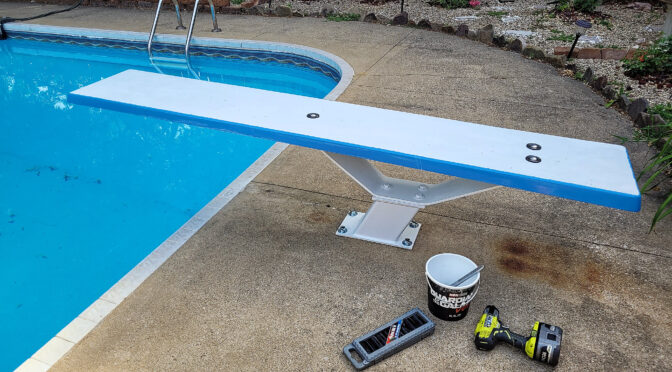
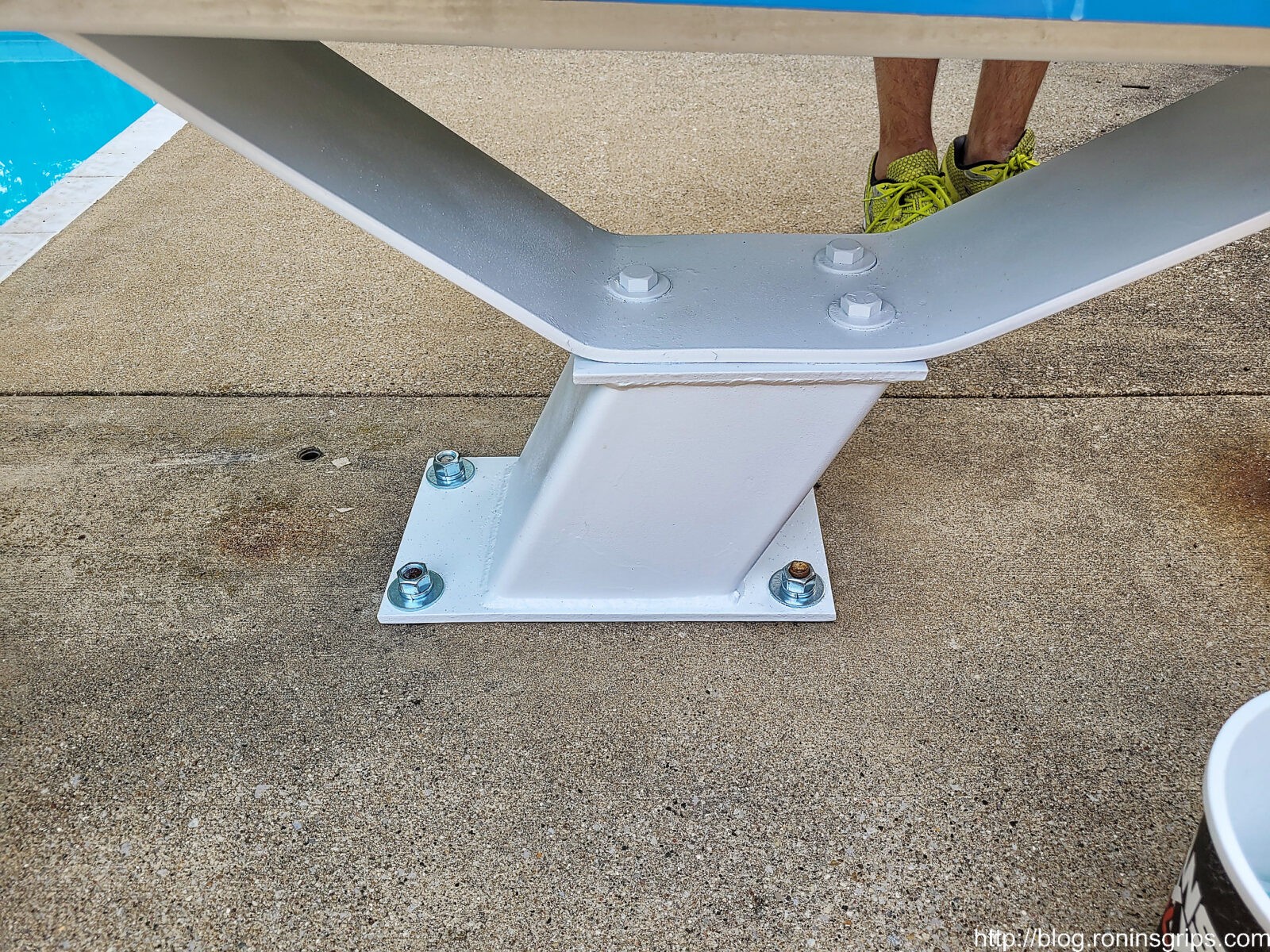
We reinstalled the pedestal and spring unit first. I bought new stainless nuts and washers so it looked better.
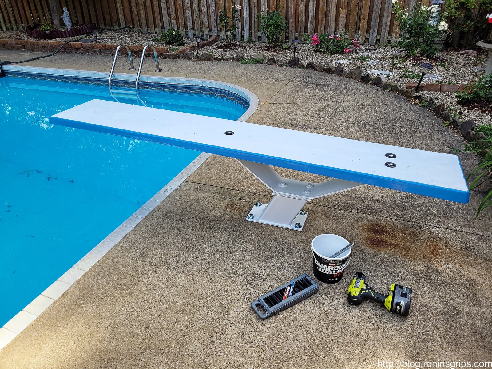
We installed the pedestal and spring assembly first before the diving board. Have a solid surface to put the support board and diving board really helped. They are too heavy to move all at once … at least for me. My son helped – those are his feet 🙂
The board is held in place by stainless hardware” 6″ carriage bolts, 2″ fender washers, rubber gasket washers under the fenders on the top. On the bottom are regular washers , lock washers and nuts. Your hardware will depend on your board’s configuration and how thick it is. We salvaged the carriage bolts and I wire brushed the tops so they looked better but I bought everything else at Ace Hardware.
Another view.
In Closing
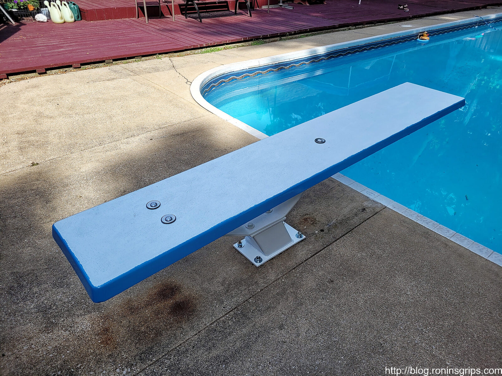
InTheSwim really damaged their reputation with me. On the other hand, this was done in a matter of days, cost us about $300 vs $800 (for the wood boards, hardware & paint) and all the kids at the reunion had a blast. So, problem solved — it worked out to our advantage actually. I’m curious to see how it holds up over time and I have high hopes given how it turned out and performed at the reunion.
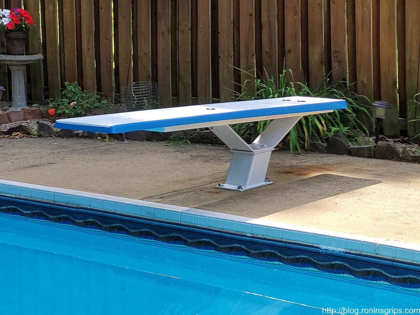
One last parting shot.
If you have a diving board, I’d bet you could do the same and save time and money as well. I hope this gives you some food for thought.
7/23/2024 Update: where a number of kids used the diving board and it held up just fine.
6/15/24 Update: Just finishing opening the pool for the summer. The board is holding up just fine.
5/23/23 Update: Board is holding up great and we’re getting ready for another summer. I just inspected it yesterday – no cracks or any signs of issues.
Note, I have to buy all of my parts – nothing here was paid for by sponsors, etc. I do make a small amount if you click on an ad and buy something but that is it. You’re getting my real opinion on stuff.
Firearms box magazines all work the same – a spring is pushing against a follower that is then pushing the ammunition on the direction needed. The follower is often pushing against at least one wall of the box magazine and dragging. This can be especially bad with steel and aluminum magazines making loading the magazines more tedious and even cause problems with feeding. It begs the question – how can I lubricate the inside of the magazine?
The knee jerk reaction is to put oil in the magazine to lubricate things. I’d recommend against this course of action because the oil will trap dirt and eventually can start causing sticking and jamming.
I’d recommend that you use a dry film lubricant aerosol instead. These sprays on and then the liquid evaporates off and what is left in place are thousands of particles that are slippery. I do not recommend any of the dry films that include a wax – like chain lubes. The wax may trap dirt as well over time.
Don’t spray anything in, or on, a plastic magazine without first checking with the manufacturer. Some plastic magazines are self-lubricating and don’t need any additional lubrication. Also, when spraying any solvent (which is basically what the dry film particles are floating in) on plastic, you risk the plastic getting gummy due to a chemical reaction – this depends on what plastic they useed. My recommendation is really for steel and aluminum magazines.
A Quick Side Note About Teflon
Up until a few years ago, I used to like Teflon, which is what Dupont, the owners of the trademark call it. Teflon was discovered by Chemours, which was a spin off from Dupont, in 1938. If you see someone selling “PTFE” – that is the generic name for Teflon. By saying their product contains “PTFE” then they don’t have to pay royalties to Dupont or risk having Dupont sue them.
So, Teflon and PTFE were selling great and then people started worrying about the safety of people eating Teflon, Teflon in the environment and so on. I’m not hear to weigh in on this but whether it was concerns over marketing, lawsuits or just the pandemic, the Dupont Teflon Aerosol Spray went on hiatus for the longest time.
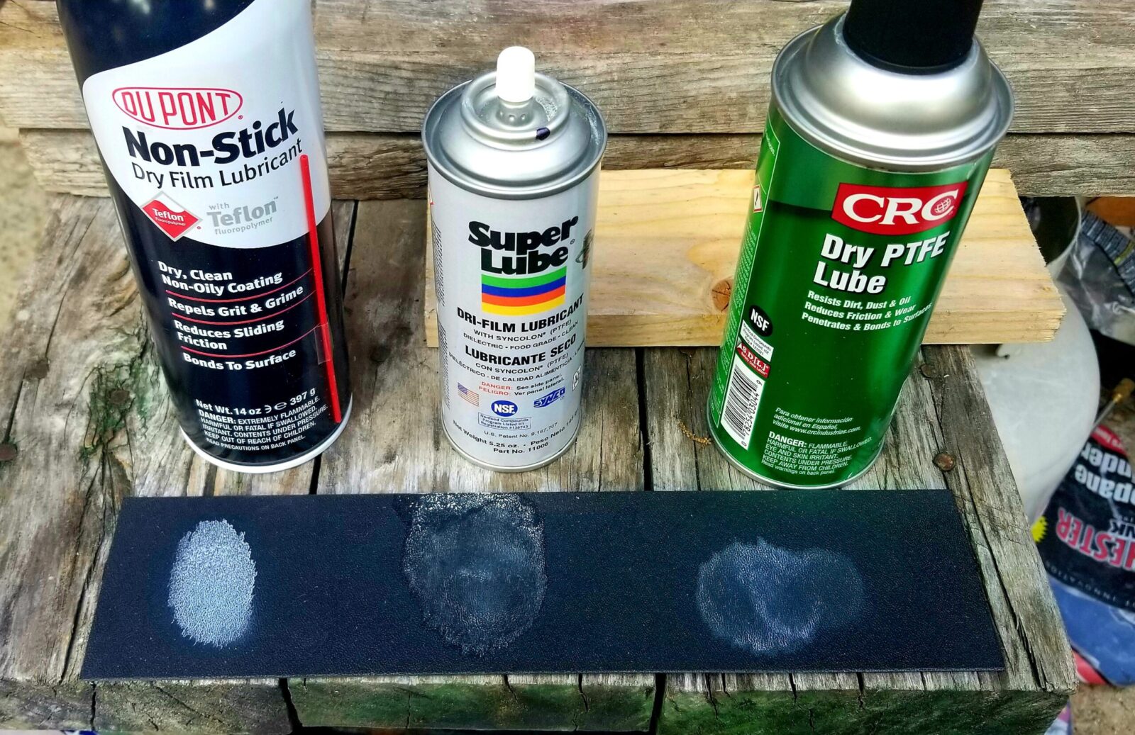
In late 2021, it re-appeared but with a different formulation. The new spray uses a ceramic now and not Teflon. I corresponded with Hank Krause the president and CEO of Finish Line Technologies – the group that actually markets the spray. I was concerned about the change in formulation because the Dupont spray had been excellent before. Want a quick way to test this? First, spray some competing dry films on a black plastic surface and see how some of them actually leave very little residue. Also look at how evenly the distribution is. Not all are the same.
I think this photo says a lot. On the left is the original Dupont spray with Teflon. In the middle is Super Lube’s Dry Film and on the right is CRC’s. This is why I swore by the Dupont dry film for years. The CRC was dry film was going to be my fall back once I ran out of the Dupont Teflon.
Nano-Ceramic Boron
At any rate, Hank told me that they have moved away from Teflon to Nano-ceramic boron nitride particles and I told him my concern that I didn’t know whether to change to a new dry film technology I knew nothing about. Hank told me the new formulation used thier same propretary technology for binding the particles to the surface and the following are benefits of the new ceramic technology over Teflon (I will copy and paste his list verbatim):
Helps extend life of the lubricant, thus delivering longer relubrication intervals
Provides enhanced lubricity
Provides better extreme pressure capabilities
Increases the high temperature operating range of the lubricant
Provides better resistance against chemicals
Helps repel water and moisture more effectively
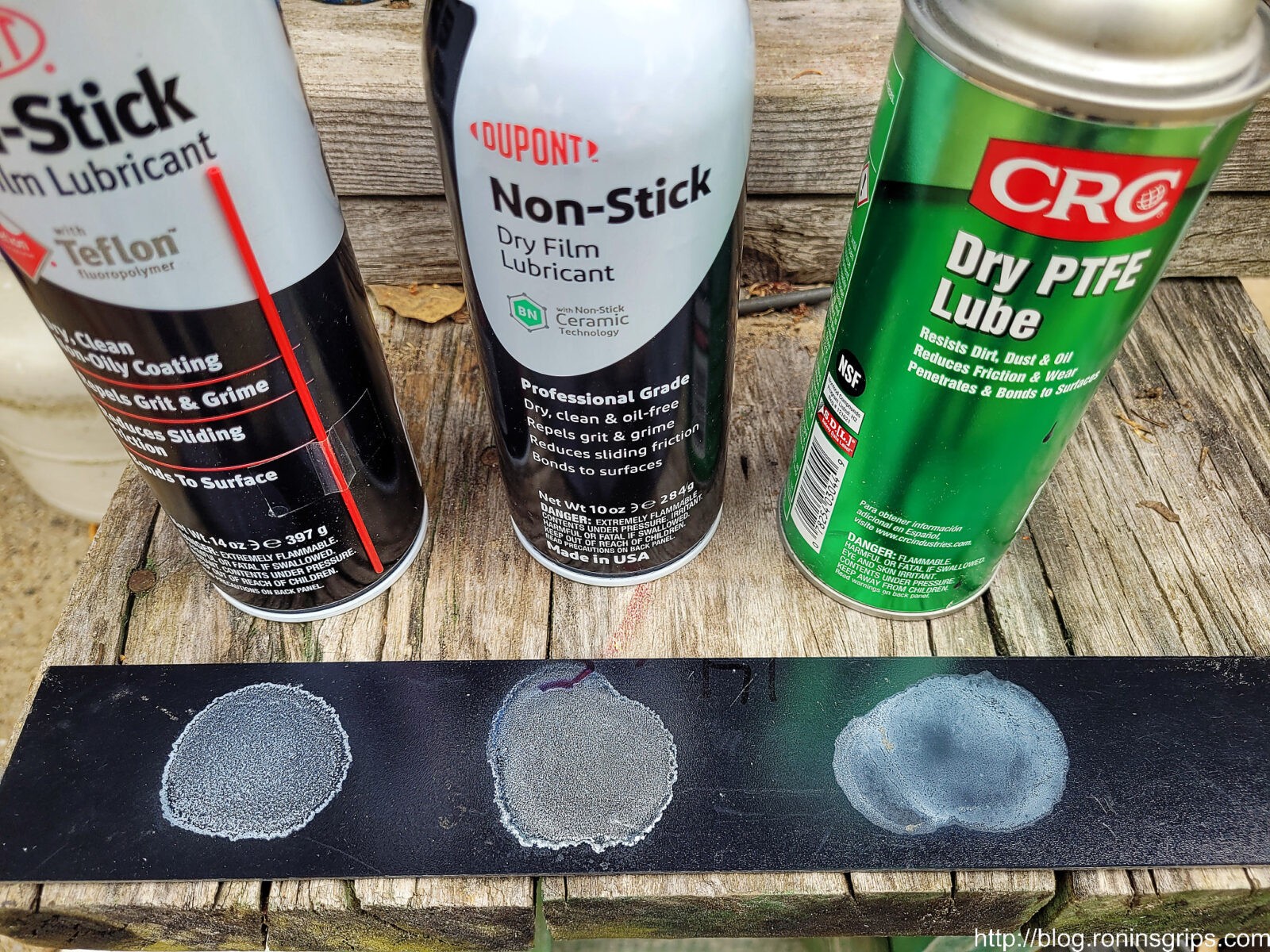
So, based on Hank’s assurances, I ordered in some cans of the spray and started testing them. The residue looked very similar to the Teflon test above – the ceramic dry film residue is also white.
The black strip is the shiny side of a piece of Kydex. I included the cans in the photo. The Dupont sprays put down the thickest coat. Interestingly enough, the CRC left a very fine film. I couldn’t find the SuperLube product – I may have tossed it – I’m not sure.
In terms of lubricity, it does the job just as well and maybe even better than the Teflon. While this may seem subjective, the lubrication seems very good with one solid spray of the ceramic both in the tube of the magazine and on the follower. Any over spray wipes right off with a rag.
With the ceramic spray, feeding rounds by hand into the magazines and unloading all feel very smooth. Bear in mind that this comment is after hundreds of loaind and unloading cycles by your’s truly.
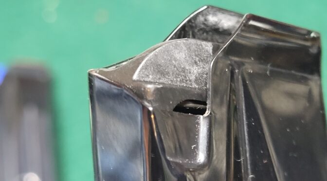
Our new second generation followers for our RIA 9mm magazines are converted from OEM followers with the final step being fine sanding paper. It’s my speculation that the ceramic particles are getting into the tiny grooves of the follower and providing excellent lubrication.
At any rate, I am very happy with the new Dupont Ceramic Dry Film aerosol for use inside firearm magazines and wanted to pass along the word. Going forward, we are using the Dupont product in all of our steel magazines that do not already have an anti-friction coating (AFC).
By the way, I cleaned out a bunch of IMI Galil magazines that I bought and you could tell there was a bunch of friction going on in the mags between the parkerized tubes and followers – the parts hadn’t worn in yet by any means. With the mags disassembled, I sprayed in a heavy coat of the Dupont Ceramic Dry Film in the tubes and sprayed both the followers and springs, let them dry and re-assembled the mags — wow! What an amazing improvement. Click here for the Amazon Listing.
I hope this helps you out.
We make a variety of magazines for the 10mm, .40 S&W and 9mm Rock Island Armory (RIA) FS A2 pistols. Click here to see them.
Note, I have to buy all of my parts – nothing here was paid for by sponsors, etc. I do make a small amount if you click on an ad and buy something but that is it. You’re getting my real opinion on stuff.