Tag Archives: Transit

Read This Before You Change the Brake Pads On Your 2015-2019 F150 Ford Transit Van

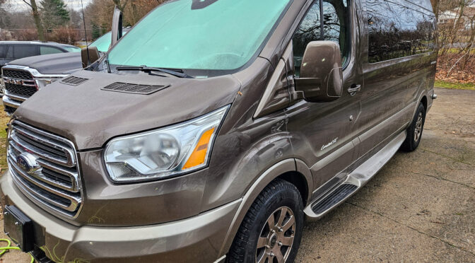
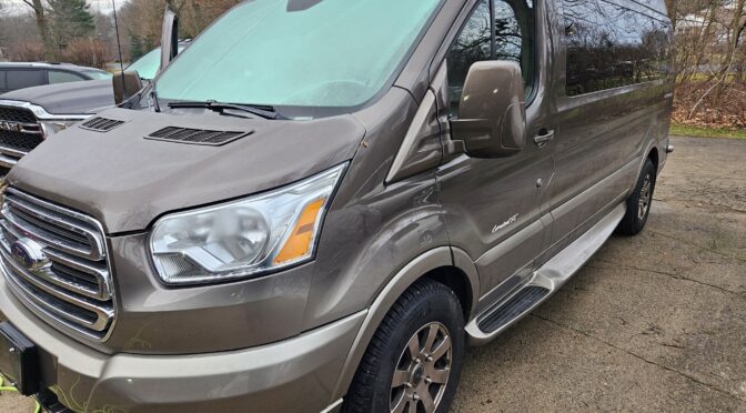
Okay, I’ve done a lot of brakes over the years – mainly on Toyotas and a smattering of other makes. We bought our 2016 Ford F150 Transit with an Explorer conversion new at the end of 2016 and the original brakes were really starting to squeek in November of 2023 so I knew it was time for them to change. It had four wheel disc brakes so I figured it would be easy. I didn’t even look up the details … oh yes, that caught up with me but let me run with my story and share you the lessons learned.

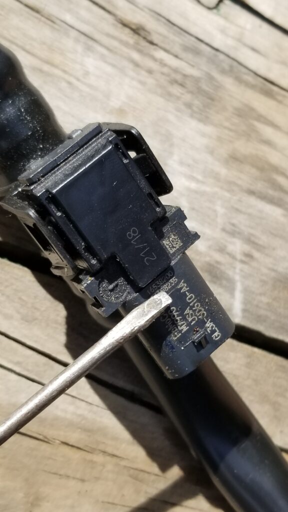
I ordered in new Motorcraft pads figuring I might as well just use OEM since O-Reilly Auto Parts could get them in quick and at a good price. I planned to flush the brake fluid too and had a good Bosch synthetic blend that I like to use.

I jacked up the van using my pillow jacks and put 6 ton jack stands underneath, pulled the tires because I planned to rotate them and dove in. I popped the master cylinder cap off and checked the brake fluid level so it wouldn’t overflow as I compressed the caliper pistons.

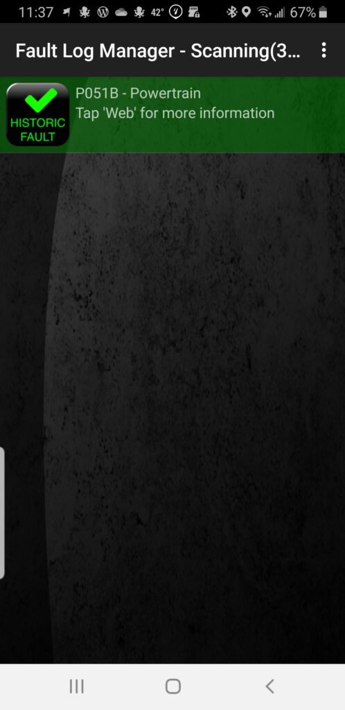
Oh man, I started with the passenger rear and could not it to go in. Okay, it was time to check the web. I realized there was something here new to me.

Getting the compressor to go back in really requires the right tool. I tried to rig a few methods and nothing worked. Note it is resting on wood blocks to take the strain of the brake lines. Be sure to clean and grease the rubber boot before you turn it back in place.

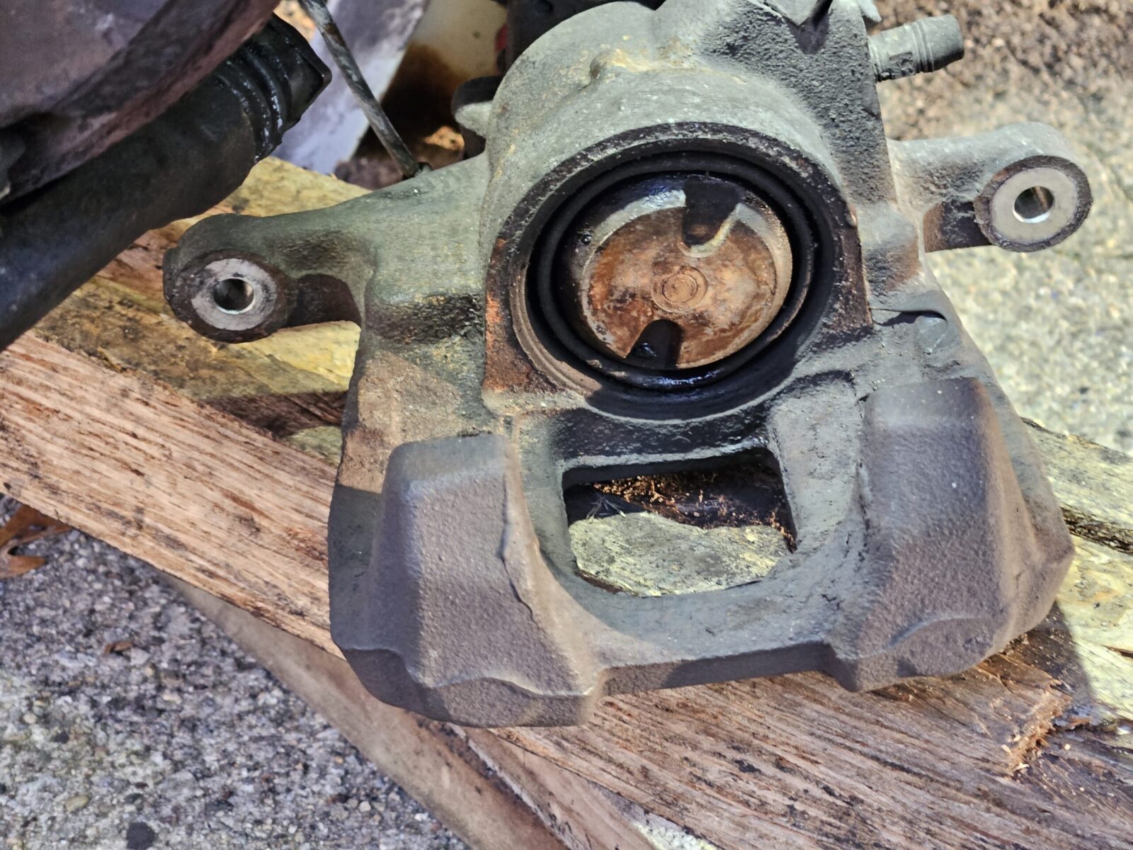
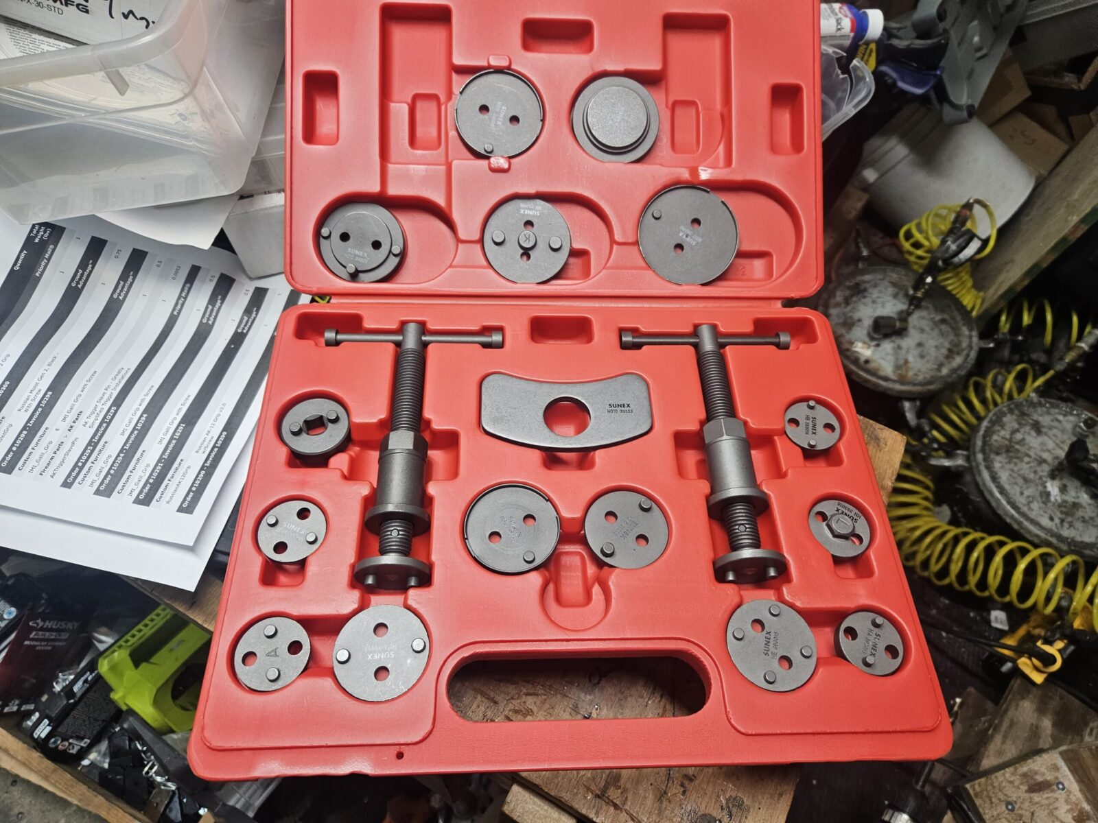
So the F150 Ford Transit is an example of vehicle where the piston screws in due to the integrated emergency brake. Okay, no problem but I could not get it to twist in. More reading and surfing … the rear passenger brake twists in counter-clockwise – not clockwise. Man, I did not have any caliper piston compressors that went counter-clockwise and neither did O-Reilly or Autozone. On, the other hand, my best friend John, who is a mechanic, did have one as part of his big Sunex 3930 caliper tool set and he loaned me the set.

So armed with the knowledge and the counter-clockwise tool for only the passenger side (driver side is clockwise), I went to work. Thanks to my Carpal tunnel and other stupid things I have done to my body over the years, I didn’t have the strength to rotate the piston – I made a 12″ cheater bar from a piece of pipe and then it went smooth. I found if I turned a bit, and then let it sit for the fluid to work its way back in the system seemed the easiest.

The front pads were easy – just standard straight in pistons. After fighting the rear calipers, it was nice to have something easy. I was so impressed by the Sunex caliper set that I bought one for furture use.

I was so impressed by John’s Sunex 3930 set that I bought my own afterwards. I honestly don’t think you can push the rear caliper back in without a counter-clockwise tool. Click here for the listing on Amazon.

The following is a pretty good video on doing the rear brake pads. My van’s brakes did not have the dampener he shows in it so I did not add one plus I used the really good Permatex ceramic brake grease on the back of the pads and contact points.

And here is a video for the front brakes:

Flushing the Brake Fluid

The importance of changing brake fluid every couple of years is something John convinced me of and the van was due for a change. Brake fluid degrades from heat and also by absorbing moisture from the air. All of this changes the chemistry of the fluid and negatively impacts the fluid’s ability to actuate the brakes. I like using Bosch’s ESI6-32N brake fluid and had plenty on hand to flush the brakes.

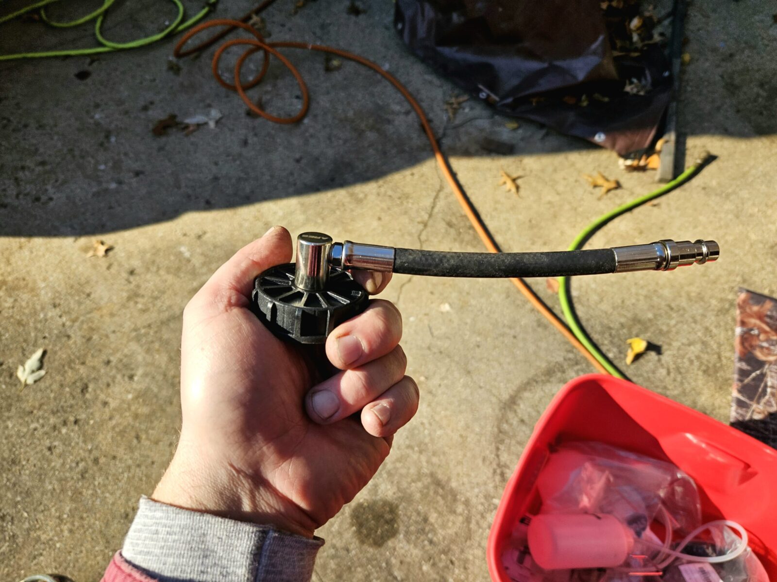
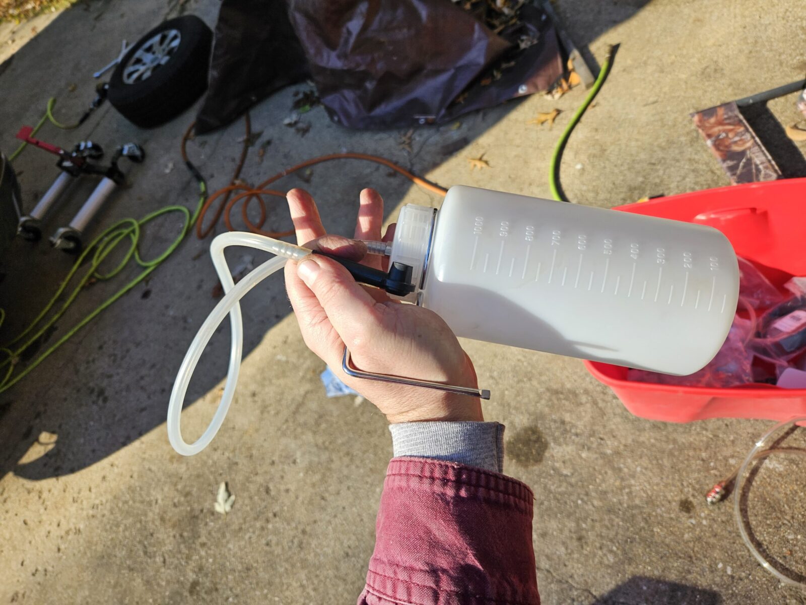
in preparation, I used my Mighyvac MV6835 vacuum bleeder to empty the master cylinder reservoir. The goal is to just empty the extra fluid in the master cylinder – nothing else. You then fill it with fresh brake flud. This way you are pushing fresh brake fluid through the system from the start.

When I first started out, I would use a vacuum bleeder to pull new brake fluid through the lines. A faster and more effective method that has lower odds of introducing air into the brake lines is the use of a pressurized bleeder.

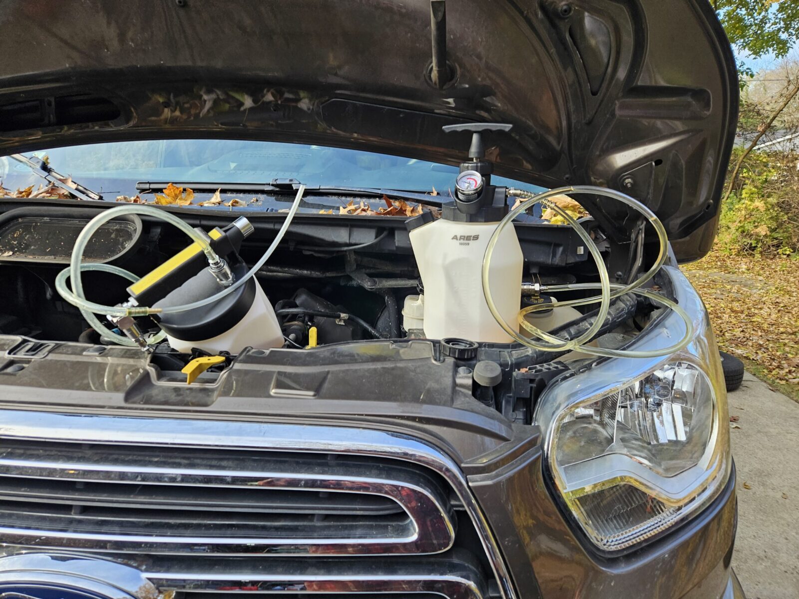
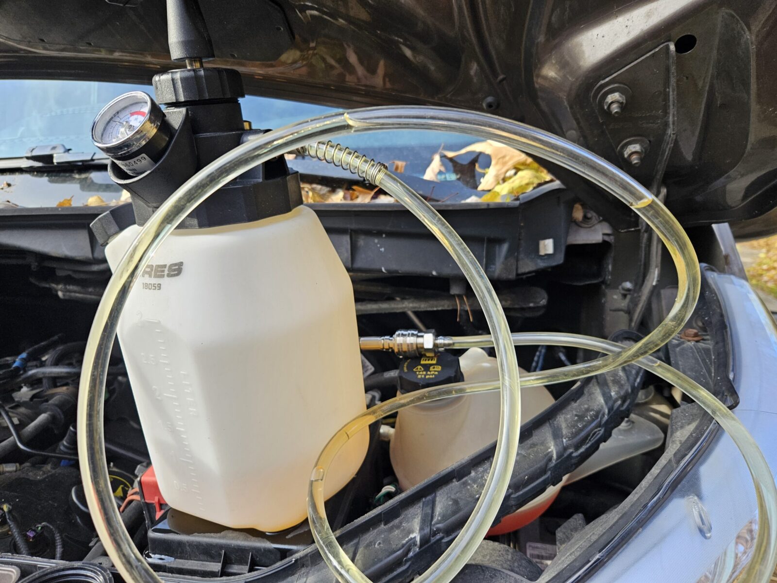
A few years ago, I bought an ARES 18036 3-liter pressurized bleeder that makes changing brake fluid or bleeding brake lines really far easier. Basically it has a hand pump, like a garden sprayer, that enables you to pressurize its tank that holds the new brake fluid. When you open a blleder nipple, brake fluid is pushed through the lines, out of the nipple and into a 1 liter catch tank.

To the left is the Mightyvac MV6835 that I used to remove the old brake fluid from the master cylinder’s reservoir. The main ARES 18036 pressure bottle is to the right.
This is the cap that goes on the master cylinder and connects to the pressure bleeder. The Ares unit is modular and there are different caps you can get for different makes and models of cars. I do not like their universal adapter – this one fits late model Fords and seals nicely.
This is the catch bottle. You push the black rubber fitting onto the bleeder nipple. As you open the valve, you can see the brake fluid going through the translucent hose. Old fluid will appear dark. I wait until the fluid coming through is clear.
Before you hook up the pressure bleeder, remove the old brake fluid if you can and then add fresh brake fluid until the full mark on the master cylinder. Do not fill it all the way to the top. When you start there will be air in the pressure bleeder’s lines. That air will just add to the air at the top of the master cylinder and the fluid will run down to the pool of fluid. In other words, the air in the master cylinder is needed as a buffer to capture any air that comes through. Only pump the unit to 10 -15PSI and then make sure it does not run out of fluid or air pressure while you work. When you first hook up the unit, pump it up to 10PSI and make sure it holds air-pressure and there isn’t a leak somewhere – if there is it is usually around the master cylinder cap or something isn’t secure/closed on the pressure bottle.

In Closing

The biggest think I learned and wanted to share was that you need that counter-clockwise tool if you want to do the passenger side rear brake pads. I recommend the brake fluid flushing at the same time – you ought to change the brake fluid every two years really – using the pressure bleeder – they are optional but I think they really help and I use my Ares on all of our vehicles.


If you find this post useful, please share the link on Facebook, with your friends, etc. Your support is much appreciated and if you have any feedback, please email me at in**@ro*********.com. Please note that for links to other websites, I may be paid via an affiliate program such as Avantlink, Impact, Amazon and eBay.


2016 Ford F150 Transit Explorer Conversion Van Custom Fuse Block

We got a good deal at the end of 2016 on a Ford F150 Transit that was converted by Explorer vans in Warsaw, Indiana. It’s no longer under warranty so I’m now responsible for all maintenance. With cold weather here, my wife reminded me that her passenger seat heater was no longer working.

First thing I did was to separate the Molex connector and test for power. The line was dead so that usually means a bad fuse. So…. that started a bunch of hunting on my part – where did Explorer wire the seats in at?

I checked the Ford fuse diagram for the passenger compartment fuse block located just above the accellerator pedal and there weren’t any likely candidates for the passenger side seat. That meant Explorer tucked a custom fuse block somewhere, but where?

I honestly expected it to be on the driver side wall between the first row of passenger seats and the driver seat but it wasn’t there. I started searching on the WWW for an Explorer van manual and found one for a Explorer van but with the same Transit F150 body style but I was not sure about the model year [Here’s the link to the manual I found but I didn’t see a date anywhere in it].

The fuse block was on the driver side wall but behind the first row of passenger seats. The plastic cover was the same color as the fabric and I just never noticed it before.

The fuse block iis on the driver’s side behind the first full row of passenger seats.
The plastic cover just pulls off.

The next is a screen shot from the manual I found and the passenger heated seat fuse location matched at least:

This screenshot is from the manual. Our Ford’s fuse block cover looks like the GM model for whatever reason. It did help me get an idea of what I was looking for though and the 10 amp passeneger heated seat fuse location matched
I actually took this after I replaced the fuse so it’s the second row from the bottom and the middle 10amp fuse.
Normally there would be a meta arc from the left leg to the right leg. Too much current was drawn and the metal arc burned away leaving a gap in the arc. That’s how most fuses work – they can only carry so much load and then the heat being generated causes the metal to melt and break the circuit.
Mission accomplished – her seat warmer once again worked.

We made a 10-11 hour drive to New Jersey and her seat worked the whole time. So, the current issue was fixed but it didn’t answer the question as to why it blew in the first place.

I have a hunch though – somebody spliced in smaller gauge wires from the main harness to the rocker on/off switch on the seat. Right after we bought the van, that seat warmer didn’t work and my best guess is that the local Ford dealer’s mechanic did a questionable splice using solderless butt connectors and the thinner wire. That means there would be a higher impedence that may be what is popping the fuse – we think this is the second time.

I have two options – an easy one and a longer-term “when I have time fix”. I ordered an ATO 10 amp fuse that has an automatic resetting breaker built into it. These act like little circuit breakers – they trip when they get too hot and then reset when they cool down. So, you have protection without a blown fuse. [Click here to see them on Amazon] I will have to see if there is enough vertical clearance because a normal ATO fuse sticks out about 0.48″ and the breaker is 1.16″ and may be too tall. In the mean time I have a spare 10 amp fuse in the glove box just in case.

The correct solution (when I have time if ever) would be to redo the hack-job splice with the correct gauge of wire and I would probably solder them together vs. the old fashioned cheap crimp on butt connector the last fellow used.

I wrote this quick post in case anybody else finds themselves having a “where is the Explorer fuse block” moment. I hope this helps you out.


If you find this post useful, please share the link on Facebook, with your friends, etc. Your support is much appreciated and if you have any feedback, please email me at in**@ro*********.com. Please note that for links to other websites, I may be paid via an affiliate program such as Avantlink, Impact, Amazon and eBay.


How to Fix A 2016 Ford Transit With a 3.7L Ecoboost Engine That Has a P051B Error Code

So, we have a 2016 Ford Transit F150 van with the 3.7 liter EcoBoost engine. It’s actually surprising how powerful that engine is because it can launch that big rectangle! However, there is an irritating recurring issue that we’ve had and that is the “P051B – Powertrain” message when the Check Engine Light (CEL) turns on. The posts and forum threads weren’t always very clear about what to do so I figured I would write about my experience to try and help people out.

How do I read ODB2 codes?

I’ve written about it in the past, I use a BAFX ODB2 scanner that connects to my Samsung phone via Bluetooth. I then use the Torque Pro app to read error codes and reset them when needed. I’ve used this combo for years and am quite happy.

Here’s the error code in Torque Pro. There is a free Torque version and a Pro without advertising. I find ads annoying so I paid some really small amount of money to go to Pro years ago and think it is totally worth it.
The ODB2 port is located just above and to the left of the brake pedal on the lower parts of the dash panel.

What is error code P051B?

The P051B code is returned when the engine control module (ECM), or the vehicle’s powertrain control module (PCM), has detected that the engine crankcase pressure sensor is returning values that are outside of normal operating limits. Isn’t that just great?

Remember the positive crankcase ventilation (PCV) valve and exhaust gas recirculation (EGR) system that cars had when you were younger? This is related to that – the fumes inside of the engine needs to be pulled out and burned. This improves both efficiency and emissions. The sensor is reporting back pressure changes of the EGR.

Now this is where things went sideways. I had a ton of rubbish posts to read through until I found out that Ford used a different name for the sensor plus it wasn’t exactly clear about where the sensor was located on what to order.

What does Ford call the crankcase pressure sensor?

No, they couldn’t call it something that obvious. Ford calls it the Delta Pressure Feedback EGR (DPFE) sensor. So, if you are searching all over for Ecoboost and something with pressure sensor in the search text, you’re going to find a ton of confusing crap. Try searching with DPFE instead.

Trying to find out what DPFE stood for was really bugging the hell out of me. A fellow told me to go look at the official 2016 Model year ODB guide from Ford and finally, on page 120 they define it as the Delta Pressure Feedback EGR (DPFE) sensor.

One other comment – Ford has a lot of free reference information available online but you have to hunt for it. Click here and select the option for Free Resources – that includes OBD2 guides by model year, body repair and much more.

So what can cause the P051B error code?

There are a number of things that can cause this code so let me list them in the order I would check them starting with the easiest:

  1. Is the dipstick fully inserted?
  2. Is the O-ring that seals the cap in the tube intact on the dipstick?
  3. Is the engine oil overfilled?
  4. Is there water/coolant in the oil causing it to be too full? The oil will be frothy and colored like coffee with milk in it.
  5. Are any of the PCV lines cracked or otherwise knocked off?
  6. Look inside the oil fill cap – is there a ton of sludge? If so, pull off the lines and look at the valves to see if they are filled with sludge. You can pull them regardless if you want to be sure.
  7. The pressure sensor might have failed… yeah….

For me, the last two times, it has been #7. It’s getting annoying. I’m now on my third sensor. Note, if it is the sensor then it is not critical but I do like knowing whether the check engine light is telling me something new or not so having it lit all the time is very annoying for me. In other words, you can drive with the sensor having problems but you will not know if a new code is being generated unless you hook up your scanner.

I think the sensor location was a poor choice

Let me tell you that it’s my opinion that the EcoBoost has a design flaw – the crankcase pressure sensor is sitting on a PVC hose and it gets fouled out by moisture and oil. The location can vary depending on your vehicle and which EcoBoost engine you have but on my 3.7L, it’s on the driver’s side of the engine,

So that’s the Delta Pressure Feedback EGR (DPFE) sensor right there in the red circle. Note the oil fill cap in the lower right of the photo to help you get your bearings.

Why they did this, I have no idea and we are now on our third sensor. The first was replaced by the dealer right after we got the van because Ford had revised the design. That sensor then failed and I replaced it myself. It turned out to be real easy.

What to order

Now this is where things get confusing. If you search hard enough, you can find just the sensor unit itself and if Rock Auto is correct, it is the DPFE-30 unit part number FR3Z-9J460-A … but it has been discontinued. I know they revised the design of the sensor to try and reduce fouling and maybe this is the older version. I returned this to Rock Auto and did not install it. I can’t confirm DPFE-30 is the correct sensor just to be clear – I think it is the older design they revised. The part that goes into the tube looked different.

What you want to buy is the assembly that includes the tubing and the sensor. This is the current part number as of my writing this blog to the best of my knowledge: GK4Z-6758-B

Here is the brand new part fresh from the dealer – GK4Z-6758-B
Here’s a close up of the assembly’s parts label.
This is the sensor still on the tubes. It is held in place by the two black “Ears” – one on the top left of the sensor and one at the bottom left. Gently pry them up with a small blade screw driver and the unit comes right out.
This is the part that goes into the hose.

Where to buy the GK4Z-6758-B Assembly?

Okay, you can get it from your local dealership for about $81 or you can buy it online for $38-42+S&H. We were going on a trip so I didn’t have time to wait and went with the dealer. While $81 may sound like a lot, if you mail order the part next day the price difference is less than it may first seem. [Note, prices have gone up considerably due to inflation – as of 5/18/22 it is $45-55 on eBay with free shipping.]

What I have been using more and more are vendors on eBay. You’ll see photos that look like what I showed above and also less detailed drawings that just show a tube. I’d go with reputable vendors that have quite a few reviews and as high of a rating as possible.

How to remove the old tube?

First, use a small blade screw driver to slide under the retaining tab and remove the wiring harness from the sensor. With the tab slightly up, it pulls straight back.

This is the opposite end of the sensor. You need to lift that tab up front just a tad with a small blade screw driver.
The tab just has to rise over that tiny nub just above the “GL3A” printed text near the right end to then slide off.
That little black tab above the white plastic just barely has lift up and then the plug can be pulled back off the sensor.

Next is to remove the tubing from the engine. There are quick connect fittings on each end. You just push the band’s tab out and the band moves out of the slot in the PVC fittings. It helps to look at the replacement hose first to see how the tab moves. With the tab held out, you can lift the tube straight up and off the fitting. It’s actually easy once you do the first one. Again, play with the replacement and you’ll see how it works.

It’s a novel design really. Push that little grey tab to the right and it will allow the fitting to be lifted straight up off the male plug. The one at the bottom of the engine you will need to do by feel but it is the same way – feel the tab, push it out and hold the tab out while you lift.

So, the replacement assembly took less than a minute to click back into place and reconnect the wiring assembly. Done. I cleared the code and a month later, it hasn’t come back.

Lessons learned – be careful while reading on the Internet. There are some people posting stuff that have no idea what they are talking about plus the super secret different name Ford chose to use for the sensor didn’t help matters.

Follow the troubleshooting list I wrote above and if it is the sensor, it is an easy fix. It took me about 10-15 minutes being real careful and I bet the next one will take 5 minutes max. I did have a hard time sorting through all the low-value posts and hope this helps you get your engine taken care of.

5/18/2022 Update: We’ve not had the problem again since replacing the tube & sensor assembly when I wrote this. One thing though is that I do my own oil now and only use Penzoil Platinum full synthetic. I’m not sure if the better oil is reducing particulates or not but just wanted to note that.


If you find this post useful, please share the link on Facebook, with your friends, etc. Your support is much appreciated and if you have any feedback, please email me at in**@ro*********.com. Please note that for links to other websites, I may be paid via an affiliate program such as Avantlink, Impact, Amazon and eBay.