Category Archives: Tools

Restored An Almost 100 Year Old Samson 5263 3.5″ Machinists’ Vise For Regular Use

Growing up, my dad has this big rusty vise on his work bench and we’d use it for all kinds of stuff ranging from holding mower blades and axes during sharpening to bending metal for brackets and so forth. I knew it came from my grandfather’s farm in New Hampshire but not much else., When my parents moved near us, my dad brought the vise with him and installed it on a tool bench in their new garage.

Life can be harsh. I have a lot of good memories about my parents but nothing really prepares you for when they pass away. I was close to my dad and to this day, when I use one of his old tools, it makes me feel good – kind of like he’s still here and happy to see me using something of his – hopefully the right way.

At any rate, when we had to sell their house and clean stuff out, I snagged the big old vise and stuck it on the floor in the corner of my shop and really didn’t think much about it for almost five years. One day I started thinking about installing a second vise in my shop near another area where I do a lot of work that requires both work holding and a vise that can withstand 50-100 ft/lbs of torque. I figured I had two options – I have a 6″ Harbor Freight unit somewhere buried in my shop that I could dig out or I could go find my dad’s and take a closer look at it.

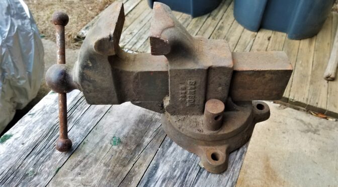
So. I dug out the old vise from under a work bench and blew off a ton of dust and dirt. The first thing that I noticed was that it weighed a ton and the second was that it was remarkably beefy and actually in really good shape other than surface rust. The action moved fairly well albeit a little gritty. Everything felt fairly tight meaning nothing seemed to be bent or broken. Last but not least, other than missing the handle on the locking nut, everything seemed to be there.

Where did Samson vises come from?

I did some searching on the web and found mention that Samson vises were sold by Sears from about 1908 to 1939 based on searching for “Samson Machinists” on ancestry.com. This page is from a 1923 Sears catalog and was copied from Vintagemachinery.org:

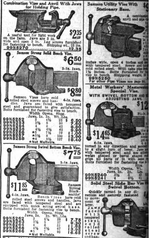
There it is down in the lower-left – 99N5263. A 3-1/2″ jaw width with a 5″ opening, weight was 37 pounds and cost a whopping $9.30!! Wow! Now, when my grandpa actually bought it, I have no idea. If my dad knew, he never said or I don’t recall – at this point, I’m really not sure.

By the way, in the catalog ad above, look at the weight of the 5266 5″ vise – 93 pounds! That would be a fun one to find. It must be enormous – I’ll have to keep my eye out for one 🙂

By the way, I couldn’t find a definitive answer about who made the Samson vises for Sears. Some people thought it was Reed but I haven’t confirmed that. If you search on Reed Vises, you will see some similar designs but I did not see an exact match. I emailed both Reed and Yost to see if they can share any insights. If I find out, I’ll update this post.

8/25/2020 Update: I got a very nice email from James about Samson vises based on some research he did: “Samson Vises were the Sears house brand before Craftsman took over in 1927. Samson Vises were made by Rock Island Vise Company for Sears and Roebuck out of Rock Island, Illinois.”

Restoring the old vise for regular use

Other than quite a bit of surface rust, it was really in very shape and I decided to use the old vise. The next thing I had to decide was what to do with the finish – it was rusty my whole life so I thought about just oiling the rust and sealing it. Another part wanted to fix it up. I honestly thought about it for a few days because I couldn’t do anything right away. In the end, I decided to refinish it. From what I could tell the vises were originally black and either partially or fully painted. My vise had zero paint on it anywhere.

Note: I am not doing a 100% overhaul to make it look like when it shipped from Sears. I wanted to clean it up some have it be functional. I just want to be clear in case any purists take issue with my use of the term “restoration”.

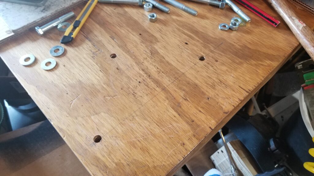
So, the first step was to disassemble the vise both to make sure it was indeed salvageable and also to clean everything. The weather wasn’t cooperating so you’ll some photos were taken indoors and some outdoors so bear with me.

Before I took the vise apart, I mocked up where I wanted it on the bench and drilled the holes. I planned to use 3/8″ bolts to secure it and they are in the photo. The bench it is on has a top made of 1-1/2″ of plywood and weighs 5-600 pounds because of the massive steel frame I built for it.
The first thing you do is to remove the sliding jaw. This is usually done by rotating the handle until the screw exits the spindle nut in the body of the vise and the sliding jaw then pulls out. Be aware that the sliding unit can be surprisingly heavy depending on the design of the vise.
The greasy looking thing is the spindle and it was in great shape. There were remnants of old grease protecting it, the screw and the ways where the sliding jaw slid (the clear tracks on the body. There were no signs of cracks – just dirt and rust in non critical areas.
To the right of the main body of the vise is the lock nut. Normally there is a small handle on it but it’s long gone. This is basically threaded onto a bolt that protrudes us from the clamp in the base. It simply unthreads. The shiny 3/8″ grade 1 bolt to the right of it will become the new handle for it.
This is the bottom of the slide. As you can see, the machined surfaces and screw are in great shape.
Somehow I always manage to miss taking a photo. The top part of the vise is secured to the base by a heavily made axle bolt. It’s the beefy chunk of steel sitting between the base and my ball pein hammer. Surprisingly, it came out very easily with a simple adjustable wrench – I just reached in perpendicular and turned the bolt not expecting it to come loose and it did. That was a very pleasant surprise. So you can also see that the bottom surface of the static jaw assembly and the top of the base are in remarkably good shape compared to the exterior.
Here’s an even closer view of the base and the locking pad bolt. You can also see the axle nut off to the back right by the back ear of the vise even better.. I think they greased it well almost a 100 years ago and that saved the inside parts. I suppose it’s possible my grandfather or dad took it apart and lubed it but I can’t ask them now.
The weather cooperated and I took the parts outside to degrease and wire brush them.
I could have punched out pins and removed the spindle nut but I figured the vise was really solid mechanically so I took a shortcut and didn’t tear the static or sliding jaws down further.
Here’s a zoomed in photo of the static jaw’s pad. I think I can barely see a screw down on the right but it would be a heck of a chore to remove them. Honestly, the jaws were in good enough shape for me.
“72C” is marked on the base. It was the only other marking I found in addition to “Samson 5263” on the side of the static jaw’s body.
After cleaning up the static jaw, the model number was clear as day – 5263.
For the really thick rust, I used my Ingersoll-Rand needle scaler to knock it off. The external surfaces on the base of the vise were the worst.
Here’s everything after degreasing with lots of brake cleaner and the paint will be Satin Black Krylon Fusion.
Here they are from another angle.
I applied four coats of paint following the directions on the can. By the way, when a paint tells you to allow two days for it to cure and you expect it to be rubbing a lot – give it the two days. I have messed up so many finishes over the years that I now follow the directions on timing between coats and how long until a full cure.
This will be my new locking nut handle. I had to grind down the nut so it would clear the body of the vise and then I abrasive blasted the surface so the black pain will stick. It was not blasted or painted yet for this photo.
From left to right – Locking nut, locking pad, and then the axle bolt.
I found it funny to set a modern cheap 4.5″ vise next to the big Samson. Look at the difference in slides! My dad always told me to be careful and not bend the slide on the Samson. Being a kid, I did what he said without knowing much. I look at the Samson’s slide now and it would take a hell of a lot of force to bend that slide!
I greased everything with Super Lube grease. I use it a lot now because it doesn’t dry out fast and has fine particles of PTFE in it to help with lubrication. I kid you not, I coated threads, surfaces, everything!
Boy did it turn smoothly on the base!
It looks and feels like new – with some character marks of course. She is around 100 years old!
The purplish tinge is the Super Lube grease. I literally coated all sliding surfaces to try and get stuff coated. I then wiped it down after this photo. Note that it also shows at the back that the vise is not perfectly concentric. It’s still tight but not perfectly centered on the base – my guess is that it never was. We’re talking being off center by about a 1/16th of an inch or less.
Here’s the locking nut with the finished 3/8″ bolt that serves as the new sliding handle. I applied blue LocTite to the nut to secure it. Note that I can turn the vise and use it from either direction on the bench. Right now it is rotated away from the side of the bench where I primarily plan to use it.
From McMaster I ordered 3.5″ copper Wilton jaw pad covers. My 4″ Wilton has original brass covers that are beefier but these copper units will work.
So you put the pads in your vise and then tap down the surfaces including the small ears on the left and right sides. The Samson is asymmetrical so I labeled the front pad so when I remove them I don’t have to fumble around figuring out which pad goes to the front and which to the back.
I also bought some Mission Automotive plastic pads that are held in place by strong magnets. These come in handy for delicate surfaces.

Conclusion

So the vise is back in use. Every time I use it, I feel good about it and hope my dad approves.


If you find this post useful, please share the link on Facebook, with your friends, etc. Your support is much appreciated and if you have any feedback, please email me at in**@*********ps.com. Please note that for links to other websites, I may be paid via an affiliate program such as Avantlink, Impact, Amazon and eBay.


Acid Etching With Ferric Chloride and Apple Cider Vinegar – Wicked Results on High Carbon Steel

I recently did two posts about building a new heated tank out of PVC pipe and a digitally controlled heating element that is both effective and affordable. This also marked my first batch of blades where I moved from my traditional hot apple cider etching to using a mix of 70% ferric chloride and 30% apple cider vinegar heated to 90-94F.

The Chemicals

Let me give you a quick overview of the two chemicals I used to make my blade etching solution:

The primary ingredient is liquid ferric chloride from MG Chemicals. It’s available in quarts and gallons and is about 38-42% ferric chloride by volume. The MG Chemicals product is well regarded and that played a big factor in my selecting it. I purchased mine from Amazon and it arrived quickly and well packed.

The second chemical is regular apple cider vinegar from the grocery store. They tend to be normalized around 5% acetic acid by volume. The brand I used was at 5% and there were other brands at 4% that I passed over – go for 5% because you need the acetic acid. I literally bought this at my local grocery store – nothing special.

The solution I made was 70% of the ferric chloride and 30% apple cider vinegar. I wore lab goggles, nitrile gloves, old clothes and am in a well ventilated area when I slowly add the ferric chloride to the relatively weaker apple cider vinegar.

The ratio was based on looking at the end results from other blade smiths and talking about what they learned. In my case, I can tell you that this combination makes for a very nice dark etch.

The Process

  1. Heat the etching solution up to 90-94F before I put in the first blade. MG Chemicals recommends the operating range from 94F to 131F and not to exeed 131F. [Click here for their technical data sheet and MSDS]
  2. The blades need to be at least 70F prior to dunking in the solution. The warmer the solution and blade, the better chemical reaction you are going to have.
  3. Clean the blade with brake cleaner throughly
  4. Abrasive blast the blade – I am using Black Beauty these days. It is a coarse coal slag based product. Note, not all guys blast their blades – some just clean them very carefully.
  5. From this point on, wear nitrile gloves when handling the blades to avoid any oils and contaminants from your skin
  6. I again use brake cleaner to do a final cleaning and make sure it fully evaporates. Some guys rub down with acetone – do what works for you but it must not leave a residue
  7. Fully submerged the blade in the heated etching solution for 10 minutes
  8. Remove the blade and wipe off the remaining solution with a paper towel [as a reminder, you must be wearing gloves to not contaminate the blade]
  9. Used clean/bare 0000 steel wool to buff the surface of the blade and remove any loose particles. Note, this 0000 steel wool is bare wool – no cleaners or anything. You find these in woodworking / hardware sections of stores – not in the kitchen area.
  10. Submerge the blade for another 5 minutes and again wiped and rubbed the blade down with steel wool. I think I repeated this process three times per blade but experiment and see what works for you.
  11. Soak the blade in warm water with baking soda to neutralize the acid
  12. Spray the blade down with WD-40 to displace the water
  13. Apply finish – I like to use a 50-50 mix of boiled linseed oil and turpentine to apply severa thin coats. This gives my blades the worn post-apocalypse look. Many guys just coat the acid etched surface with oil to inhibit rust.
Here’s a small 5″ khukuri where all steel surfaces have been blasted.
Here’s the finished khukuri just before I mailed it to its new owner.
Here’s a look at the solution in the tank.
Here is one of the etched damascus blades. The beads on the blade are oil.
Here’s an even closer look at the finished blade.

Summary

I’m definitely very happy with the results and will be using this solution going forward.


If you find this post useful, please share the link on Facebook, with your friends, etc. Your support is much appreciated and if you have any feedback, please email me at in**@*********ps.com. Please note that for links to other websites, I may be paid via an affiliate program such as Avantlink, Impact, Amazon and eBay.


How to Make An Affordable and Effective Heated Tank For Acid Etching – Part 1

I like to acid etch blades that I build using apple cider and/or ferric chloride. I also manganese park firearms and tools. Assuming the part is prepped properly, there are two common needs in all of the above – the part must be submerged and the solution heated. So you have two options, buy a stainless tank and heat source or build one using PVC pipe. These next couple of posts are going to dive into how you can build an affordable and very effective heated tank to finish you parts plus have some fun doing it.

PVC or CPVC?

We can use rigid PVC pipe as the container to hold the etching solution. It’s cheap, easy to find and easy to work with. I need to explain a few things first about what we can and can’t do with it.

In plumbing, rigid PVC pipe has an operating temperature of 140F degrees. The reason for this is that PVC is a thermoplastic and begins to soften with heat and will burst due to the pressurized water. We don’t have much pressure to worry about other than atmospheric pressure but you don’t want to push plain PVC towards 200F – it really isn’t designed for it.

If you want to do parkerizing at 190F, then you need to use CPVC pipe. CPVC rigid pipe has extra chlorination that allows it to withstand 200F while delivering water under normal household pressures. Fun trivia, CPVC was invented by Genova Products in Michigan.

If you are trying to figure out what you are looking at, if the pipe is white, it is probably PVC. If it is cream colored, it is probably CPVC. It ought to be labeled/printed on the side of the pipe also but be on guard for people putting stuff in the wrong bins at a store or clerks not knowing what is what.

In this post, I am working with regular PVC purchased from my local Ace Hardware because the tank is for acid etching knives and will the liquid will be 90-110F on average. If I ever build one for parkerizing, it would be in CPVC. The reason it’s an “if” is that I already have a big stainless steel parkerizing tank but it’s a headache to drag out and set up whenI need it.

The Parts List

Basically, we are going to build a tube with a cemented permanent cap on the bottom and a threaded cap at the top. You can go with any size you want. For most blades I work with, 3″ is plenty and I wanted it to be portable.

Let me give you a piece of advice – it’s aways better to be a little bigger than you think you need than to find that out later. When in doubt, make it wider and taller — within reason of course. Note, I knew a 3″ diameter and about 16″ tall would meet most of my needs but not all and I was fine with that. I’ll pull out my four foot stainless tank when I need to do something huge like a cleaver.

In terms of parts, you need the following:

  • A length of pipe of the diameter that is needed
  • A coupling for that size
  • A threaded adapter for that size – you cement it onto the end of the pipe and it gives you a national pipe thread on the other end
  • A threaded plug that fits into the adapter
  • An end cap of one type or another. If you use 3″ or 4″ pipe, you can use a toilet flange adapter to actually both plug the end and allow you to connect it to the wood if you aren’t making it very tall. I would be worried about torque on a tank with an overall length of 24″ or more. In those cases I would cement on a normal end cap and build up a crade around the pipe to support it.
  • You may want a drain for a big tank – I didn’t need one for this little unit because I can easily lift it even when it is full of the acid etching solution.
  • PVC cleaner and cement (note, PVC and CPVC use different cement)
  • Wood to form a base to keep the pipe from tipping over so it needs to be both wide and heavy enough. Really it’s up to you as to how you secure it to be vertical. I like a mobile base but you could tie it to something, etc.
  • A heating source and controller – we’ll get into more detail in the next post.

Weight Considerations and a Drain

Bear in mind that this tank can get pretty heavy if you plan on using really big piple (6″ or bigger). Water weighs 8.34 pounds per gallon. You will find that other liquids can weigh more. Apple cider vinegar may be around 8.6 pounds and ferric chloride might weigh 10-12 pounds per gallon depending on the concentration.

I bring the weight up because if you are thinking of building a big tank, the weight is going to add up and you may want to install a drain near the base. There are two big reasons you need to think about this – you may want to move the unit around plus you will need to change the solution as it ages and breaks down from use.

This is my 3″ tank I just built. The toilet flange us availab;e for 3″ and 4″ pipe and is handy for smaller tanks. I’d build a cradle/surrounding frame to support a bigger tank.

The pictured tank is about 16″ tall with 3″ pipe and has about a gallon of 70% ferric chloride and 30% apple cider vinegar in it. I can move it around very easily and portability was one of my design goals.

Assembling The Pipe

PVC is really easy to work with. You cut the pipe to the length you want or have the store do it for you. I use a big miter saw for stuff like this to get nice square ends and use an airline to blow all the loose plastic out (wear safety glasses).

To “glue” the pipe together, you first prime the surfaces and then apply the cement. Note, PVC and CPVC use the same primer but different cement. In this case,I use Oatey’s purple primer and clear cement. Read the directions on their box just to make sure. Bear in mind the solvent is really thin and is going to run everywhere – especially in cold weather.

I’m a creature of habit. I’ve had very good luck with Oatey products so I stick with them. There are other brands out there such as Ace’s own private labled stuff, but I stick with Oatey to avoid surprises. When following their directions and using their products, I’ve not had a joint fail/leak yet,

The Base

To make the tank stable, you need a big enough base both in terms of area and weight. I had some old 1×12 stock that I chopped into squares and stacked if four deep for weight. You can do whatever you want and your goal is stability, however you get it.

I centered the flange on the first board and screwed it in. I’m not sure I would trust the flange to handle the potential torque of a long pipe. For me, once I get around 24″ overall, I am going to build a cradle and not subject that flange to a ton of stress.
I then applied epoxy and clamped the layers together. I was kind of experimenting as I went. Just one piece of wood wasn’t heavy enough so I then added the additional layers after. I could have glued the base and then used longer screws to secure the flange had I known more up front. I wound up with four layers of wood in the end.

I have another tank that is full of a boiled linseed oil an turpentine mix that I use for hydrating wood handles in khukuris and cleavers that I restore. It has a rounded end bap on the bottom and the base is more like a heavy cradle made up fo 2×4 lumber that gives it weight and then goes up the sides to provide support.

This is a 4″ pipe with a wood scaffold base. It’s very stable. This is a tankI use for moisturizing and treating long wood hanndles.

Summary

That’s it for now. In the next post we are going to talk about heating the tank. This is where I did the most experimenting and can share some ideas with you.


If you find this post useful, please share the link on Facebook, with your friends, etc. Your support is much appreciated and if you have any feedback, please email me at in**@*********ps.com. Please note that for links to other websites, I may be paid via an affiliate program such as Avantlink, Impact, Amazon and eBay.


How to Make An Affordable and Effective Heated Tank For Acid Etching – Part 2

In the last post, I covered the basic construction of the tank. In this post I want to talk about heating the tank. Thanks to mass production of digital temperature switches, you can build a digitally controlled heated tank for a very reasonable price.

Why Does Heat Matter?

In case you are wondering, heating the solution does matter. Years ago, in 1889, a chemist by the name of Svante Arrhenius proposed an equation that would later bear his name. Basically, a chemical reaction increases as the level of activation energy increases. The reason temperature enters in as that you are raising the energy in the liquid, more energetic particles are bouncing around and increasing the volume of reactions which means that more successful reactions will occur as well. We can use a rule of thumb that for each 10C increase in temperature, the reaction rate will double and for each 10C drop, it will be cut in half. To sum it up, cold=bad for chemical reactions. As a side note, this is also why marginal batteries fail when cold weather hits.

So what this means to acid etching is that in my cold unheated shop in the Winter, reactions are going to be real, real slow. Thus, I must have a way to heat the chemical and the submerged part to improve the reaction.

The Heating Element For The Tank

The first thing I wanted to do was to keep the cost down and the second was that I didn’t want something that would get so hot that it would melt the PVC. I had a 30 foot length of roof heating tape from when we cleaned out my dad’s garage that I had been thinking about for a while. It always makes me feel good when I use something that was my dad’s. (There are tons of options on Amazon – click here.)

These roof heating cables use AC voltage to warm up and melt ice are readily availble and are designed not to get so hot that they melt the shingles but also are designed to be spread out and not right next to each other so I was going to need to test the design. I planned to wrap the tape from the bottom of the tank until I ran out cable with each coil right against the previous. I was counting on convection of move warmer fluid up and cooler fluid down but I wasn’t really sure how it would sort out.

Another nice things about these heating cables, or heating tapes, is that they do not use a lot of electricity. The 30 foot model my dad had was spec’d to draw only 150 watts at 12 volts. That makes for a nice portable unit that you can run off just about any extension cord.

So, step one, I applied the tape to the empty tank and secured it just with 3M 3340 aluminum HVAC tape. This is the tape made for higher temperatures with an aluminum foil backing – it’s not dcut tape. I then watched the temperature with my Fluke 62 Max IR thermometer. You need an accurate thermometer and the Fluke has served me very well – it’s proved itself to be accurate, reliable and durable – it’s been bounched around a lot in my shop.

So, the temperature slowly climbed but made it all the way up to 170F before I shut it down. The PVC still felt pretty good but it was way hotter than what I wanted. Just plugging the tape in and calling it done was not the answer. Sure it would heat the liquid up fast but I couldn’t safey leave it unattended. I needed something to control the temperature but use the heat tape.

Please note that there are pipe heaters that are a different creature. Some of them need to be submerged in water or wrapped around a steel pipe. Do not use those types of heaters. There are a ton of different names buy you are looking for the cable or tape that is put on roofs to melt ice dams, etc.

Solution – Use A Digital Temperature Controller

I thought I knew the switch I was going to buy until I did some further research. Some controllers are very easy to set up and others seem a bit more confusing. I opted for the WILLHI WH1436A Temperature Controller 110V Digital Thermostat Switch. All you do set set the temperature for ON and the temperature for OFF. That’s it. If you want them, there are some more advanced settings that you can explore if you want but this seemed like just what I needed.

I undid the top few coils of the heat tape and rewound them with the temperature probe wrapped in them. I then used aluminum HVAC tape to secure the top. I set ON to 90F and Off at 95F and plugged the roofing tape into the controller.

I inserted the temperature probe a few coils down and secured the top with 3M Aluminum HVACtape. Note the small cable clamp screwed into the wood base securing the bottom of the heater tape and preventing it from unwinding.

I started watching with the Fluke meter and since the temperature based on the probe was 40.2F, the controller turned on power to the switch and the tape heated. It did cut power around 95F but the tape continued to warm up even so by about 10F so the peak temperature was between 103-105F according to the Fluke. This was actually within my acceptable range. I was just ballparking 90F but even 105F was fine by me.

The digital controller works well. I’m going to leave it loose some I can move it around depending on what I am working on and were.

There was one minor hitch I noticed during experiments – the controlled heat took over an hour to warm up the fluid. If I unplugged the tape from the controller and plugged the tape straight into AC power, the fluid heated way faster and the pipe never felt soft – probably because the tape was heating part of it and the acid was cooling it. This was the fastest way but risky because if you forget, it’s going to get quite hot. I let the fluid get up to 160F during one run and decided that I would only do this if I was in a big rush and going to be there working the whole time. If I wanted to play it safe, letting the controller keep things safe was a better bet. I could have also sped things up by setting the OFF temperature higher, say at 110F and that’s something I will experiment more with.

The temperature controlled tank worked out great on these high carbon steel damascus blades.

Operating Temperature Range

Do not heat ferric chloride past 131F. Remember that the heating element will still heat the chemical another 10 degrees or so past the upper limit you set as OFF.

The operating temperature range from MG Chemical is 95-131F. Based on my results, I don’t see a need to push the upper limit.

Click here both for their technical sheet and MSDS sheet,

Conclusion

I had about $30 in the PVC and fresh glue, nothing for the base, the controller was $29.99 and the roof heat tape was free but if you bought it, the price would be around $30. This definitely falls in the affordable category plus I turned out some really cool etched damasus blades using the controlled tank. If you want to know a bit more about the chemicals and my process, click here.

When I was done, I let the tank cool down, screwed on the lid, cleaned things up, coiled the cords up and stored the tank for the next use.

If you find this post useful, please share the link on Facebook, with your friends, etc. Your support is much appreciated and if you have any feedback, please email me at in**@*********ps.com. Please note that for links to other websites, I may be paid via an affiliate program such as Avantlink, Impact, Amazon and eBay.


Why The Mophorn Pneumatic Lift Is a Huge Help When Working On Cars and Trucks But Has One Small Issue You Need To Address

Nothing like getting old and realizing that most of your joints hate you. I bring this up because I have two manual pump floor jacks that I have used countless times over the years and the oldest is probably 25 years old – literally. Well, let me put it this way – I had no problem pumping the handle to lift cars and trucks 25 years ago but starting about two years ago, the action really started to cause elbow and shoulder injuries I had to flare up. It got so bad that I had to make a choice either to stop working on vehicles or to find a different approach.

I work on cars and trucks in our driveway so a permanently installed lift was not an option. It had to be something portable. My first thought was to get a low profile air-over-hydraulic jack that is mounted in its own wheeled carrier. They have an incredible lifting capacity (around 22 tons) but they are heavy (around 80 pounds), slow (air over hydraulic is many things but fast is not one of them) and expensive (they start around $200 and just go up from there). What really stopped me was the weight and the cost. I can’t lift or drag as much weight as I used to and the entry-level units were a tad more than I wanted to spend.

So, I kept digging and ran across pneumatic/air jacks. Think of the air suspensions you see under a big rig. Basically one or more air bladders fill with air and lift the top of the jack. They max out in terms of lift height around 18 inches and 3 tons of lift but it depends on the model. Definitely spend some time researching before you buy. I found that I needed to think about:

  • How low I needed the unit to collapse down to fit under our cars to get in position prior to lifting
  • How much weight did I need to lift
  • How high I needed the unit to lift
  • How much did it weigh?
  • What was it going to cost?

I then started reading listings on Amazon plus paying careful attention to review scores. I also talked to a mechanic friend of mine about the safety of the unit and what his thoughts were. He told me to consider two things: 1) always immediately put jack stands in place and 2) don’t lave the unit out in the sun and weather thus harming the rubber. Those suggestions made a lot of sense to me.

On January 8, 2019, I wound up buying a Mophorn Pneumatic Jack, 3 Ton, Triple Air Bag, with a 16″ lift height for about $150 with free shipping. The unit arrived with just little bit of assembly needed. I recall I had to install the handle and the pressure line but that was it.

I get about 15″ of lift at 90 PSI.
Left lever is the exhaust and due to the lever design, you can adjust how slow you want to drain air out. Even if you hit it and have an “oh shit” moment, you typically have a few seconds before the vehicle starts to go down. The middle unit with the pull ring is the safety blow off valve. The far right lever is the air inlet and there is a Milton M-series male plug under the Milton quick connect female fitting. If you want a reliable air system, use Milton fittings – they last.

As you can guess from the sticker above, the lift is made in China and the instruction sheet is pretty terse but it’s really not that hard to figure out. I do want to cover a few specifications with you and convert them from metric to US customary measures – these are from the owner’s manual included in the kit unless otherwise noted:

DescriptionMetricUS
Capacity3,000 kg6,613 lbs
Air Pressure5-10 Kg/cm^271 to 142 PSI
Air pressure from label on handle – presumably the recommended pressure8 kg/cm^2113 PSI
Minimum Height145mm5.71 in
Maximum Height400mm15.75 in
Lifting Time5 seconds5 seconds
Working Temperature-69C to +50C-92F to 122F

What have I lifted with it?

When I say “lift”, I am talking about the front end or the back end – not the whole vehicle.

  • 1994 Toyota Corolla DX
  • 1996 Toyota Land Cruiser
  • 2000 Toyota Camry
  • 2006 Toyota Solara
  • 2008 Toyota Highlander
  • 2016 Ford F150 Transit
  • Others more or less along the lines of a Camry or Highlander

There are a few things I have noticed

First, let me point out that I like this unit and would recommend it but there are a few things I want to point out:

  • The highest my lift will go is 15″ and that may be a function of my only running 90 PSI to the jack
  • I don’t think it actually can lift 3 tons. It bogs down on the front of our old 96 Landcruiser and also our full size F150 Transit. Again, I think it’s my lower air pressure. This summer I might plumb a dedicated 120 PSI line and see what that does. It will depend on time and money.
  • There are stabilizing cones made from steel inside the jack. Maybe 1 in 20 lifts they need a whack to start coming down. I may polish and lube these if I get a chance.
  • The rubber is pretty thick on the bladders. With that said, I do store it indoors away from the sun and the weather. I’m writing this a year later and the bladders show zero signs of wear.

The One Little Thing You Must Do: Blue Loctite Your Screws!!

I have used my jack many times since I bought it. Starting around September I was hearing faint air leak and thought the jack had bent. When I had time I found out that the bottom screws had loosened up and air was simply escaping from between the gasket and the bottom plate. I was surprised and disappointed to note that none of the screws had any thread locker applied to any of them. Many were in varying states of coming lose.

The unit is well made. The air bladders secure to that steel plate you see on them and then that assembly bolt to the dolly.
It’s the screws that attach the bladder to the while disc-shaped plate in the previous photo that came loose. Here are the metal stabilizing cones. I wish I had polished and lubed them when I had it apart and will go back and do that at some point. I did apply air tool oil to the cones after cleaning them of a gritty dust that probably dated back to when they were manufactured.
Before re-assembly I put a thin bead of Permatex Blue RTV gasket seal on the rubber gasket and then applied Blue medium-strength Loctite to each srew and brought them down lightly. I then went criss-cross lightly bringing down each screw to firm and then applied a final torque of 11 NM (about 8 ft-lbs or 97 in-lbs.

I then did the same thing to the top plate as well just to play it safe. No more leaks.

The reassembled bladder assembly then screws back down to the baseplate of the dolly. Note, this photo is actually from when I was taking it apart. The screws were so scuffed up that I just replaced them. Did I mention I use this a lot?

The following is the exact jack on Amazon that I bought and this review is about:

Bottom Line

I would buy this again and recommend it as well – just due the Loctite thing I mentioned. Note there are other Chinese suppliers on Amazon also but they do not get as good of reviews as the Mophorn units so my recommendation is only for that brand.


If you find this post useful, please share the link on Facebook, with your friends, etc. Your support is much appreciated and if you have any feedback, please email me at in**@*********ps.com. Please note that for links to other websites, I may be paid via an affiliate program such as Avantlink, Impact, Amazon and eBay.


How To Run Oil-Lubricated Air Compressors in Cold Weather & Not Trip Breakers

Folks, my shop is unheated and the space where my 60 gallon oil lubricated Ingersoll Rand (IR) 2340L5-V sits can get well below freezing – sometimes even well under 20F. That presents a challenge because the lubricating oil gets thicker as it gets colder and this puts more and more of a load on the motor to start. What usually results is a tripped breaker -I know my 30amp breaker would trip regularly until I took some corrective actions.

One option you can run with is to run variable weight thinner synthetic oil in the winter. I don’t want to run into issues with my pump so I stick with IR straight weight compressor oil so I’m not really keen on doing that. There are guys who will disagree with me and that’s why I point out the option.

The solution I put in place works great. I simply put two Kat’s 24025 25 watt heating pads that measure 1″x5″ on each side of my pump level next to the oil reservoir. These heaters were designed to warm fluid reservoirs including those with oil. I’ve used a ton of them over the years for warming pressure tanks and what have you and have not had one fail yet. My oldest units are probably 3-5 years old and no problems — I just use them during the Winter.

This is the Kat’s 24100 4×5 heater that I have at the bottom of my compressor to keep the condensate from freezing.

In terms of heating my compressor’s pump, I just run mine non-stop in the Winter but if you’d really rather only run them when it is at or below freezing, there are thermal power plug adapters that only turn on when it is that cold. Note, at 25 watts they do not heat fast. If your pump is real cold it could take it a while to get up to an acceptable temperature. That’s one reason why I just let them run and I can turn the compressor off independent of the heaters.

Along with the little 1×5 units, I use one larger 4×5 Kat’s 24100 pad at the bottom of my compressor to allow me to drain the condensate that would otherwise freeze. I do not run that non-stop as it is 100 watts. It’s on a thermally switched outlet that turns on at 35F and off at 45F. Yeah, it may run more than I need it to but I haven’t invested in a better controller yet for that part. I will list the digital controller I plan on getting some day so you can decide.

Installing is about as easy as it can get. The Kat’s units have a self-adhesive back and must be installed before you plug them in or you will ruin them. Clean the surface of oil and dust, peel the cover off the adhesive, stock the heater on and wait the prescribed time then plug it in and it warms up. Note, I have only used them on steel surfaces. They get hot and I would not be inclined to install them on plastic for example.

Kat’s products are made by Five Star Manufacturing and they have a ton of different products for different applications. Click here for their website.

Note: There aren’t as many Kat’s brand heating pads around now but there are a lot of different brands and sizes on Amazon – click here to see them.https://amzn.to/3J1Hpzn

The setup works great. No more tripping breakers due to thick oil caused by cold weather. I hope it helps you out.


If you find this post useful, please share the link on Facebook, with your friends, etc. Your support is much appreciated and if you have any feedback, please email me at in**@*********ps.com. Please note that for links to other websites, I may be paid via an affiliate program such as Avantlink, Impact, Amazon and eBay.


Replacing the Pressure Switch on an Ingersoll Rand 2340L5-V Air Compressor

I live in a rural area and wind up doing a lot of my own repairs. About 2-3 years ago I invested in a 60 gallon Ingersoll Rand (IR) 2340L5-V air compressor which is their entry-level “Value Line” of industrial compressors. In hindsight, had I known more about “value” meaning “we made it cheaper”, I would not have made the purchase. Yes, it’s held up way better than my consumer air compressors but a buddy’s big Quincy compressor rocks and that is another story.

At any rate, I use a ton of compressed air for pressurizing my casting tanks and running all kinds of air tools. One of the reasons I went with the 2340L5-V was that I kept burning out the little 30 gallon consumer compressors. Failure is a big deal for me because when a compressor goes down in my shop, almost all work stops.

At any rate, I knew something was going on with my compressor before it stopped running completely. At the end of the air fill cycle that brings the tank back up to pressure, the switch would shut off but then there wasn’t any bleed down to relieve the pressure on the pump. This meant that the compressor may or may not restart without tripping the 30A breaker and it got worse with time. After this got really annoying, I decided it was time to fix it.

I did some reading and it turned out there were two likely culprits – either the check valve was leaking air back or the pressure switch was failing. I had problems with the check valve on other compressors so I jumped to conclusions and replaced that first. It didn’t fix the problem. Argh.

This is the 23474653-R pressure switch. It is just the switch and does not include the gauge, blow off valve or bleed off line (unloader) that you see.

So that left the pressure switch and this is where things just went sideways and I got frustrated. In searching online and calling the parts department, IR’s own parts department sold me the wrong switch and I was down for almost a week. So you don’t go nuts, you must make sure people know if you have the 2340L5 or the 2340L5-V because their pressure switches are different. You can make the better switch from the 2340L5 work but it will take a bit of re-plumbing the lines to do so. I may actually try that some day.

Next comment, do not go with the model number on the pump housing itself. The model number you need is printed on the big silver decal on the tank – not on the pump. The pump will say “2340” but that is not your specific model.

Right there outlined in yellow is the model number you must go by. 2340L5-V in my case.

For whatever reason, IR parts sold me the wrong part even though I asked the fellow to confirm it was right. So, frustrated and with my compressor down, more discussions were held and web searches done and the correct part for the 2340L5-V’s pressure switch is a 23474653-R. Interestingly enough, Tractor and Supply Company (TSC) is an IR dealer and the local store had one of these switches on the retail shelf. This gives you an idea that they are viewed as a wear item if a retailer is going to tie up the money and shelf space to stock one. It was $79.99 and they only had one so I called and confirmed with the clerk that they had one before I drove over. I’ve had way too many situations where a website said “X” was in inventory and when I went to the store, it was not so I try and confirm now. Thankfully, I drove to the store and picked it up.

I removed the cover already but this is what comes in the box. You will need to move your gauge, blow off valve, bleed down line, rear pipe plug and electrical lines over from the old switch to the new one.

Comments On The Swap

So, when it comes to the repair, it’s a fairly easy swap. I took a few photos from different angles to make sure I didn’t forget anything plus I labeled anything that might get turned around. Gone are the days when I try to keep it all in my head. Between my age and interruptions, I find it way too easy to forget things.

Two real important safety comments. Fully drain the compressor – in other words let all of the air out and open the floor drain. Why open the floor drain? Because it’s your double check that it is empty.

Second, please make sure the power is cut. I use a heavy stove/appliance cord going to a wall outlet. I both cut the breaker and unplug the cord. Why do both? It’s your double-check. If you are in a multiperson environment, follow lock out procedures.

Note the top two poles are the hot legs coming from the wall.
Folks when you go to remove the blead-off / unloader line, it is held on by a compression nut fitting. Let me give you a piece of hard won advice – use a flare nut wrench if you can to support as many sides of the nut as you can or worst case use a proper fitting box end wrench. Don’t ever use an adjustable wrench or you will likely round the corners off the nut as the jaws of the wrench give. Now IT does give you a new nut and that is plain 1/4″ copper tube if you screw up bad but you can re-use that whole piece if you are careful with removal and re-installation.
Okay so the top two terminals are the hot legs from the wall. The middle set of terminals are the hot legs going to motor. Down on the bottom you have the neutral from the extension cord and the green/neutral going to the motor. These are thick wires in a tight space so be careful working things into position.
Here’s an odd little thing I encountered. The pipe plug that goes in one unused position of the switch is actually 10mm. Why? I have no idea. The 10mm fit best so I ran with it. Everything else was SAE. For example, the housing itself that you see just above the wrench uses a 3/4″ wrench.
Use pipe thread tape on all fittings and properly support the pipes and what not so the right things you care about are moving in the right direction. For example, I used a pipe wrench on this nipple to keep it from turning while I both removed the old pressure switch and installed a new one.
Lesson learned, stay organized. That is a small magnetic tray. I cleaned all fittings and installed new pipe thread tape before reinstalling them.

Bottom line is that I installed the new pressure switch and the compressor proper bled off the pressure from the pump after cycling. In talking to IR parts they mentioned to me that this is the most common reason for the bleed down not to happen in my series of compressor – not the check valve. I believe that now. The pressure switch seems cheep and really strikes me as a consumable part now. Lesson learned.

By the way, I found out during the actual swap that IR printed the part number on the inside of the switch cover. Why hidden inside? If they had it on the outside, then this would have all been way simpler.

Also, next time my compressor stops unloading, I am going to order one of these switches vs. waiting for failure and having to scramble. It’s my fault for putting it off but I had a ton of other things going on and eventually it bit me.

I hope this helps you out as well. Bottom line, if you have a 2340L5-V then the correct pressure switch you need to order is the 23474653-R. That way you can avoid the drama I ran into.

One last shot of the right pressure switch box with the part number on the top right 🙂

If you find this post useful, please share the link on Facebook, with your friends, etc. Your support is much appreciated and if you have any feedback, please email me at in**@*********ps.com. Please note that for links to other websites, I may be paid via an affiliate program such as Avantlink, Impact, Amazon and eBay.


Here are switch listings on eBay. Be careful that it is a real IR part or a quality replacement vs. an inferior knock off that will not hold up.


Preparing a Pressure Washer For The Winter

Whether you call it them pressure washers or power washers, these are darned handy machines to have around. For portability, we use models with a gasoline engine and are on our second one. The first lasted for a few years until one wither the water in the pump turned to ice and finally cracked the housing. As they say “and that was that”. I thought about just buying a pump but for a little bit more we bought a whole new unit. My friends also cautioned me to always winterize the unit to make it last through Michigan winters. That was 6-8 years ago and I have learned a few tips to share.

By the way, the photo above really is of our pressure washer. I don’t have space to store it indoors so I really do need to Winterize it. Regardless of the brand you buy, there are three things I would tell you to do.

Drain the gas and/or use a mix with Stabil

Assuming you have a gasoline pressure washer, you might want to drain the gas from the tank and run the unit until it stalls. There are two reasons for this – gas can spoil if left untreated and also, when it evaporates out of the carb it will leave a gummy residue that may need to be cleaned out. In my case, my washer only sits idle a few months so I don’t always drain it. I’ve not had a problem so far. I always drain my chain saws because they may sit an unpredictable amount of time.

The second recommentation that you can do along with the first is to always add Stabil, a gasoline conditioner, that keeps it from breaking down for at least 12 months. I always add it to all of my gas cans when I fill them.

Blow out the system and disconnect the gun/wand and hose

What did in my first pressure washer was not draining the water out of the pump. I made a small air fitting by taking an old piece of hose and a 1/4″ air fitting that I can screw into the pressure washer and blow all of the water out of the pump, lines and wand. It works great.

I just use junk hose to make the adapter. You just need a male hose fitting on one end and a way to connect your compressor on the other.

If you really want, you can buy pre-made winterizer fittings for $12-20. The above fittings were all made with old stuff I had laying around.

Drain The Soap Tank

Don’t forget to drain the soap tank also. You don’t want it to freeze and crack anything. I did forget this one year and had to rebuild the fitting that cracked with epoxy.

Don’t forget to drain the soap from the plastic soap tank.

Add a Winterizing fluid

I then use an aerosol based pump winterizer. It can blow the water out by itself technically but I’m paranoid. I use my compressor to blow out everything and then I disconnect the air lines and wand/gun. I then connect the Briggs & Stratton 6151 Pressure Washer Pump Saver Anti-Freeze and Lubricant to further protect against freezing and to lubricate the pump and prevent the O-rings and seals from drying out. This works great for me and one can will last me 2-3 years at least.

This is what I use and have never had a problem.
All you do is connect the hose assembly to the hose inlet and push the trigger. The foam will come out pretty quick – it doesn’t take a lot. Note, stand to the side or you will wear the foam. I kid you not that it took me two years of wearing foam until I remembered to stand to the side when filling the unit with foam. Also, remove the hose and wand/gun before doing this or you will use a lot of material to purge them also. You can blow them out or even hang and drain them vs. using this stuff unnecessarily.

Now a ton of reputable companies sell some form of pump protector / winterizer. I suspect one or two companies actually make it and then applies different labels – Generac, Briggs & Straton, Stabil, etc. Just go with a name brand and I bet you will be fine.


Summary

I hope this helps you out. My current pump is still going strong even though it is out in the winter weather every year. The paint is fading but it is mechanically solid.


If you find this post useful, please share the link on Facebook, with your friends, etc. Your support is much appreciated and if you have any feedback, please email me at in**@*********ps.com. Please note that for links to other websites, I may be paid via an affiliate program such as Avantlink, Impact, Amazon and eBay.