In the last post, I gave an overview of the project and parts used. Rather than cover a lot of stuff again, here’s a link to my series of posts on building an AR Lower and rest of this post will be my covering the building of the 12.7×42 upper.
Stripped Upper Receiver
A Beowulf uses a standard AR upper receiver with an enlarged ejection port. My Alexander Arms (AA) upper has an ejection port that measures 3.02″ wide x 0.62″ tall. In case you are wondering, I grabbed on of my PSA 5.56×45 ARs and its port measures 3.02″ wide x 0.49″ tall.
The PSA’s port is about 0.35″ from the bottom of the base of the picatinny rail that has a casting line in receiver to the inside of the port. The AA still has the stepped lip for the ejection port door even though it doesn’t use one so I am measuring to the actual opening. I’m not sure how standard that measure is but offer it up – it does correspond with the top of the case deflector in the three ARs I looked at. The AA’s port is also about 0.35″. Note, this is an approximate. I’m trying to use caliper to measure a curved surface.
So this means you can either buy a standard upper and enlarge the port yourself or you can buy an upper that comes with the port already enlarged. Satern makes a big bore upper that supports the Beowulf round. Rather that bothering machining an existing upper, I went with the Satern receiver.
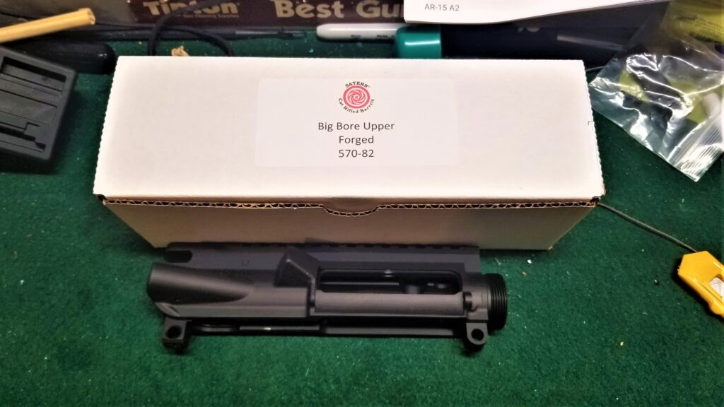
The Satern’s opening is 3.02″ wide x 0.62″ also. The slight difference is the measure from that casting mark under the rail to the entrance – it’s about 0.38″. Again – that last measure is a ballpark depending on the angle I hold the calipers. I can tell you for sure that it slight further down than the AA’s port.
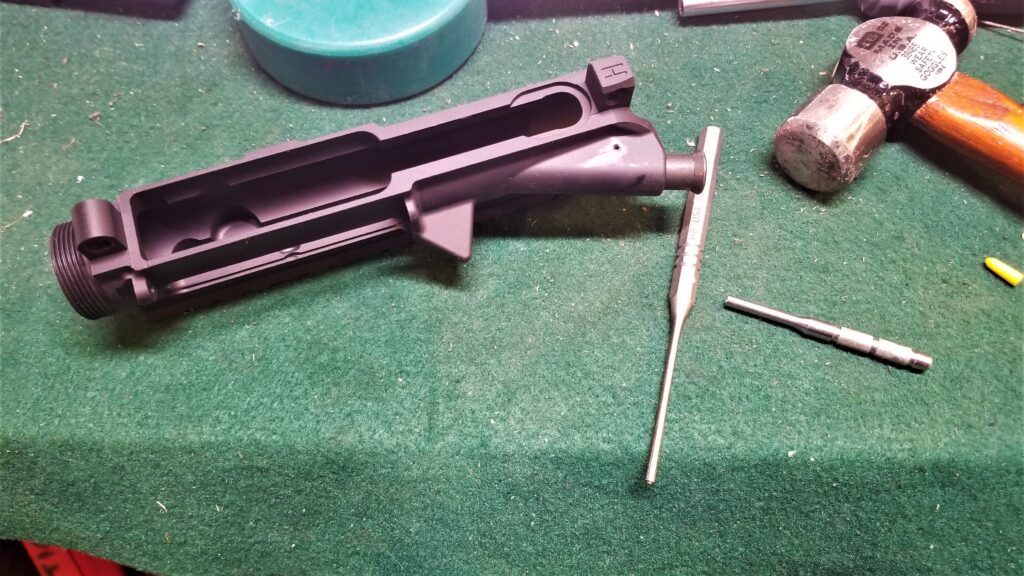
So, to assemble the base components on a stripped upper is easy. I’ll go cover each of the basic parts to make a complete upper.
Install the Forward Assist
It’s interesting when you read about the history of forward assists on the M16. Eugene Stoner, the original designer of the M16 platform, did not think one a forward assist (FA) was needed and that if one had to force the bolt to close then it would probably cause a problem later when it came time to extract. Colt, however, wanted to make government buyers happy. The US Air Force didn’t think the FA was needed but the Army demanded it have one and later claimed it was for psychological reasons.
I have a mixed opinion on them as do many people. If you must force the bolt closed then something is wrong. I’ve used it relatively little and there was, in all cases, underlying problems *but* it might help you fire that one round that makes a difference. So, I build with them, they are there but I very rarely use them.
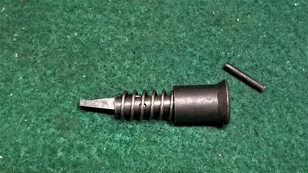
With that said, the Satern upper has a provision for a FA and you need to install one. I used a model from CMMG and installation is easy:
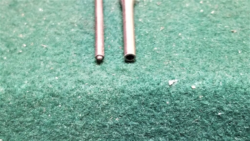
- Lightly greased it first with Superlub grease and then inserted the assembly in into the hole with the pawl (the little “foot”) rotated towards the bolt.
- Press the FA all of the way into the tube and while holding the FA all the way forward, use a roll pin starter punch to drive in the roll pin that will hold it in place.
Note, have some wood or something under the tube that the FA is going into. Supporting it will make driving the roll pin into place much easier. The starter punch gets the pin into the hole and then the standard roll pin punch will help you tap it into place until flush. It does not require a ton of force. - Test the FA – it should spring in and out.
- Turn the receiver upside down and press the FA button again, you should see the pawl come out of it’s tube in the side of the receiver – it should be oriented/rotated to push on the “teeth” on the side of the bolt (yeah, that’s what those “ribs” in the side of the bolt are for.
Installing the Ejection Port Cover Assembly
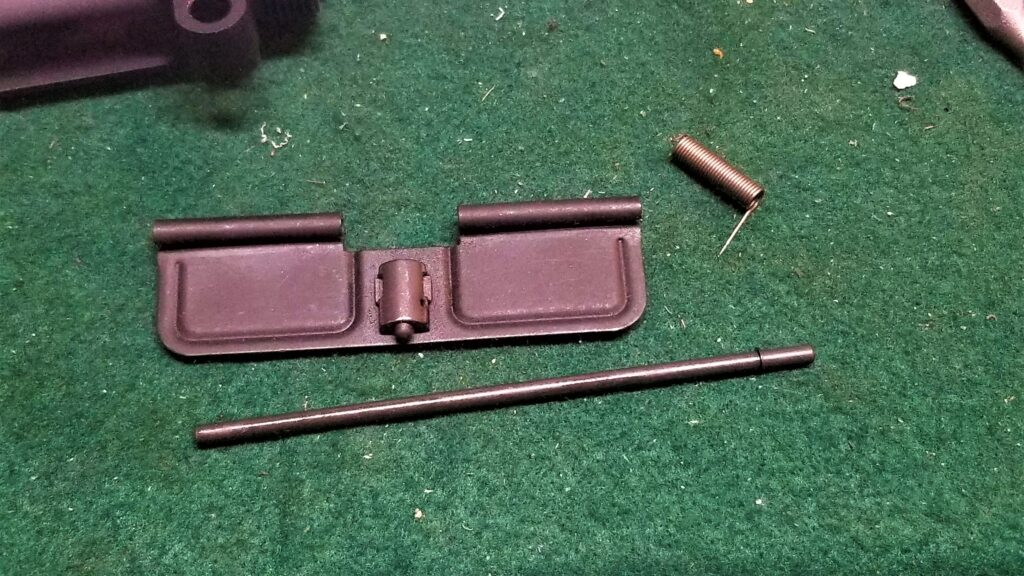
As you read above, the Beowulf has an enlarged ejection port so a standard-sized 5.56 ejection port cover/door will not work. Okay, you have two options at this point. Either skip the cover or buy one. I went with the latter because Satern makes an enlarged cover that fits their receiver.
In terms of installation order, installing the cover does need to be done before the barrel locking nut because the nut will block installation later. Here are the steps:
- If the clip hasn’t been installed on the pin yet, you need to tap it on square with a small hammer. I’ve had guys tell me they’ve used pliers for this step but I haven’t done that. Note, be careful and pay attention – the little clip can really fly away if it isn’t tapped into place squarely.
- Lay the upper receiver down with the ejection port up. I usually place it such that the barrel nut threads are to the right.
- Note the spring has a long and a short leg. The long leg will rest on the cover and the sort leg will rest on the receiver.
- The basic installation is to move the cover into place, slide the pin in from the left (back of the receiver) towards the right and sliding through the tube in the cover but stop just before the opening where you will put the spring.
- Note the spring has a long and a short leg. The long leg will rest on the cover and the sort leg will rest on the receiver.
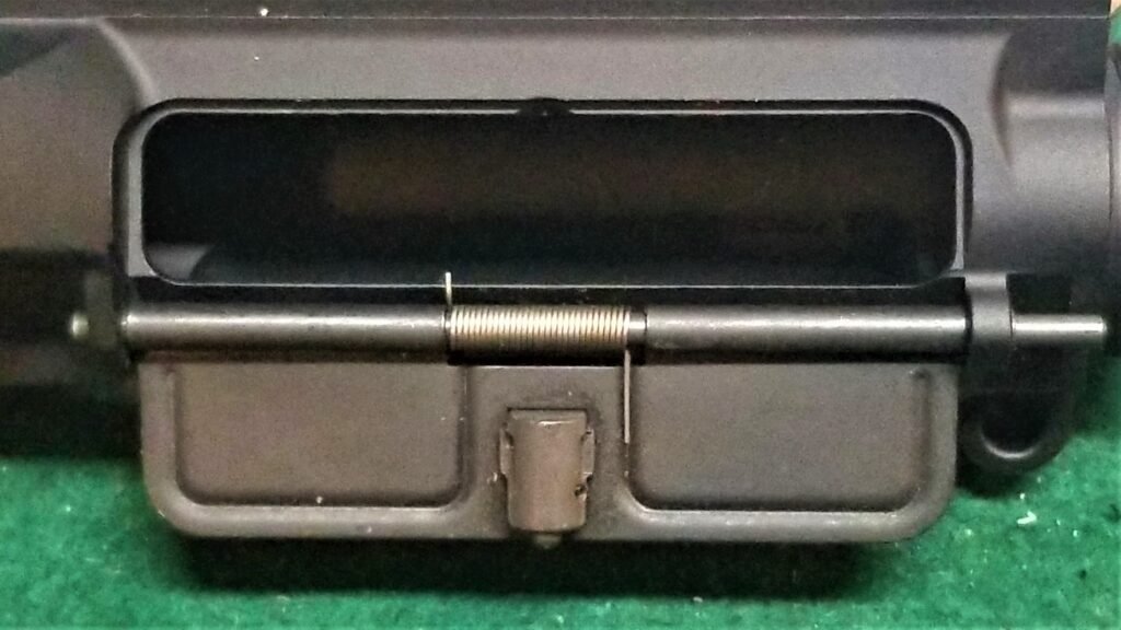
- This is the part that drives me nuts – I pivot the pin away from the receiver just enough to install the spring. The short leg of the screw will go against the receiver and you need to twist the long end to create the tension.
- I then try and hold it all in place while sliding the pin the rest of the way in. There are videos out there on this and different people do it different ways. It can be frustrating so just be patient.
- Yes, the right end of the pin is just sticking out because once you install the barrel nut, it’s not going anywhere.
- You should be able to put a finger in from the bottom of the receiver well and pop it open. I do this as a quick test.
- To actually function test the cover, temporarily install the charging handle and bolt. Close the cover with the bolt closed as well. When you pull the charging handle back, the cover should spring open. If it does not, then you have most likely installed the spring wrong.
- Last step is to use some clippers and trim the small portion of the small leg of the spring that is sticking into the ejection port to get it out the way. Don’t do this until after you have the cover installed and tested.
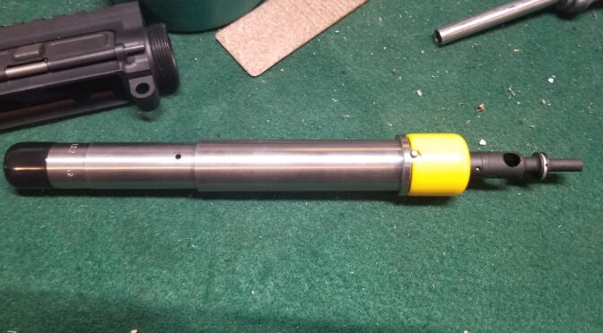
The Barrel
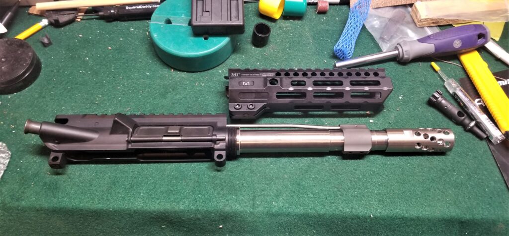
In my opinion, you’ve just finished the hardest parts of the upper. I hate that little demonic dust cover spring just to be clear 🙂 The next three are pretty much tackled together because aftermarket handguards come with their own barrel but that needs to be installed.
First off, I went with Satern because the barrel in my first 12.7×42 rifle was made by them and was very accurate. Second, I liked that they sold it with a matching headspaced bolt. My biggest problem with my first rifle was that Radical Firearms did not include the right bolt. [Click here for my post about that first build if you are interested.] A common misconception is that a 12.7×42/Beowulf cartridge uses a 7.62×39 bolt. This is not correct. The depth and extractor are different. 6.5 Grendel does use the same bolt as 12.7×42. So, when I bought my Satern barrel, I bought it with a matching bolt just to play it safe.
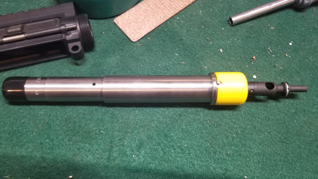
| The barrel is threaded 3/4-24. This is not the same as an Alexander Arms barrel. I asked Satern why and they told me they wanted a thicker wall. Whatever the reason, you need to remember this thread size when you are buying whatever brake or muzzle device you plan. |
One of the really cool design aspects of the AR system is that the barrel just slides into the receiver and is properly indexed by the pin shown above fitting into a corresponding notch in the upper receiver. The barrel is “locked” into place via a barrel nut. A gas tube then slides into place over the barrel with the gas tube entering the upper receiver above the locking at the top. I’ll come back to that shortly.
In Conclusion
After test fitting, it’s time to get into the installation of the barrel, nut, gas tube, handguards and brake. I’d say that’s enough to cover in the next post!
Please share the link on Facebook, Forums, with colleagues, etc. Your support is much appreciated and if you have any feedback, please email us in**@*********ps.com. If you’d like to request a report or order a reprint, please click here for the corresponding page to open in new tab.
Note, I have to buy all of my parts – nothing here was paid for by sponsors, etc. I do make a small amount if you click on an ad and buy something but that is it. You’re getting my real opinion on stuff.