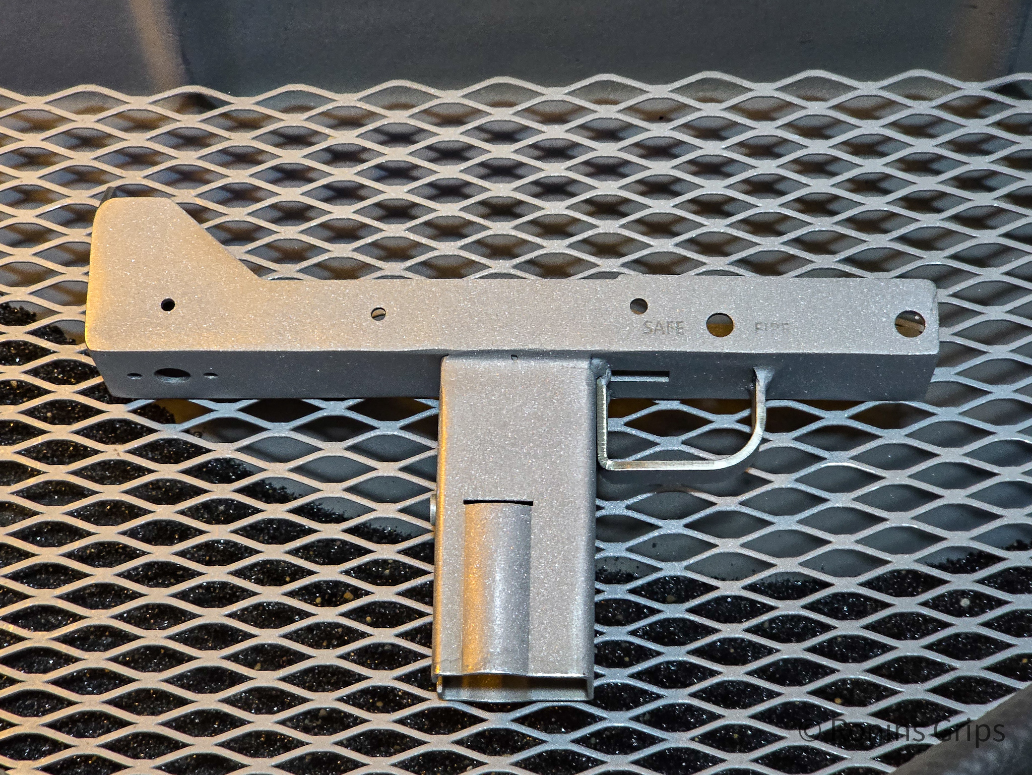
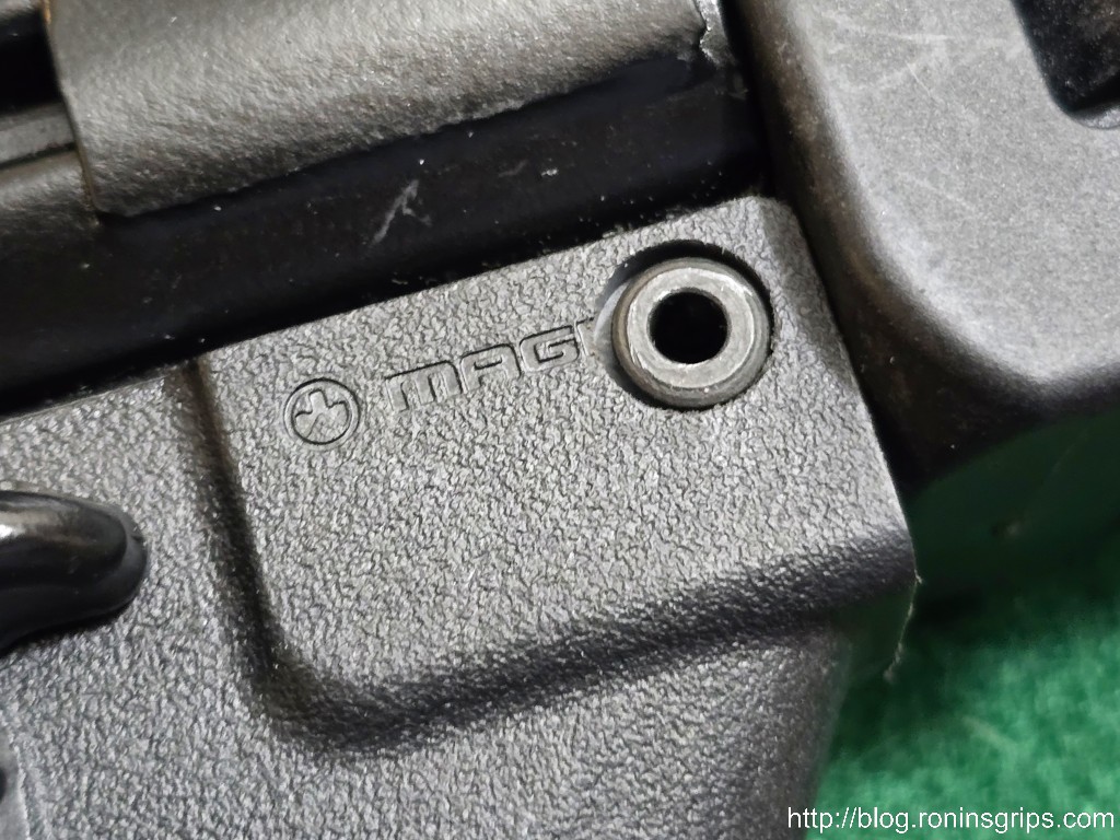
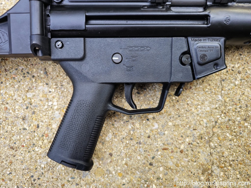
Velocity Arms finishes their VMAC9 uppers using a “manganese phosphate finished IAW 5.3.1.2 of Mil-STD-171” which is a fancy way of saying maganese park, heavy coating, class 2, oil coated. Of course the military gets into a lot of details further specifying it in MIL-DTL-16232. At any rate, Velocity Arms’ uppers are a nice rich dark black manganese park finish and I had a pretty good idea of how to duplicate it based on past experience.
I’m not going to get into all of the chemistry details – if you want that, click here for Wikipedia. I am going to point out, there are two types of park – zinc and maganese. Zinc is more of a grey or grey/green. Manganese is dark grey to black. What I have found purely based on experience is that an abrasive blasted clean steel surface will turn black in a fresh park solution and it approaching boiling and left in for 30-45 minutes.
Surface Prep is Critical
One thing I have found is that you just can’t take steel and drop it in park solution. You may get little to no reaction plus if there is oil or grease on the steel, you may contaminate your park solution so bad you have to discard it.
What I do is put on nitrile gloves, clean the part with brake cleabner thoroughly. If it’s bad, use an ultrasonic cleaner with a good cleaning solution. When the part is dry, then abrasive blast it. I use Black Diamond blast media from my local Tractor Supply (TSC) store. Never use sand – the dust from that is incredibly bad – really, really bad – for your lungs because it goes in and doesn’t come out. With Black Diamond, it does a wear out so I watch my parts and when the blasting starts taking too long, I replace it.
Clean everything and blast the part. The steel should all have a frosted look or it probably didn’t get blasted enough. If you get done with parking and an area didn’t take, hose it down, dry it, blast the affected area and a bit of the surrounding area and try again.
When I am done blasting, I clean it again with brake cleaner, let it dry and it’s time to go into the Manganese park solution.
I usually brew my solution and let it start heating up and aging while I get my parts ready.
A Manganese Home Park Formula That Really Works
I have used this formula for years. One ingredient though, Prep & Etch , is getting hard to find so you will either need to find an alternate or make your own mix.
This recipe generates about two gallons of mix so figure out your ratios if you want to make more:
2 gallons of distilled water (it gives more consistent results because impurities have been removed – sold at supermarkets and drug stores).
2 “biscuits” of clean plain 0000 steel wool (thinner steel wool dissolves faster hence the use of 0000 grade) – Click here for them on Amazon or here for eBay
1 cup of Klean Strip brand Phosphoric Prep & Etch (or other phosphoric acid etching solution around 35-45% concentrate per the Prep & Etch MSDS sheet. Dilute the acid if higher. For example, if 100% pure then go 60 water:40 acid to make the diluted acid solution that you add to the mix. This is not the ratio in the park solution itself – you can always experiment with the ratio that works for you). I can’t find Prep & Etch at any local stores but my local Ace Hardware is carrying something similar called “Ospho” and the SDS sheet identifies it as 45% phosphoric acid and it ought to work but haven’t tried it yet. I had two gallons of Prep & Etch and that amount has lasted me a number of years because I don’t do a lot of parking but you get the idea. Click here for Phosphoric Acid on Amazon or here for eBay.
6 very rounded tablespoons of manganese dioxide (available at pottery supply stores, Amazon or eBay). Do NOT mess with batteries. You may read about guys who open up batteries to get the manganese – don’t do it. Just buy the actual manganese in bulk. It’s cheap and you know what you are getting.
Heat Source & Vessel
Some years ago, I bought a Camp Chef Explorer two burner stove off Amazon and I really like it. It’s sturdy and can run off any of the common propane tanks. Also, there are many different sizes of stoves out there but I wanted a beefy two burner to be able to also heat my stainless tank when I park long parts.
I use 20 pound tanks because they are easy for me to move. I just swap cylinders when they pass their inspection date but otherwise get them refilled at my local Ace Hardware. Surprisingly, they tend to have the best prices in the area for propane.
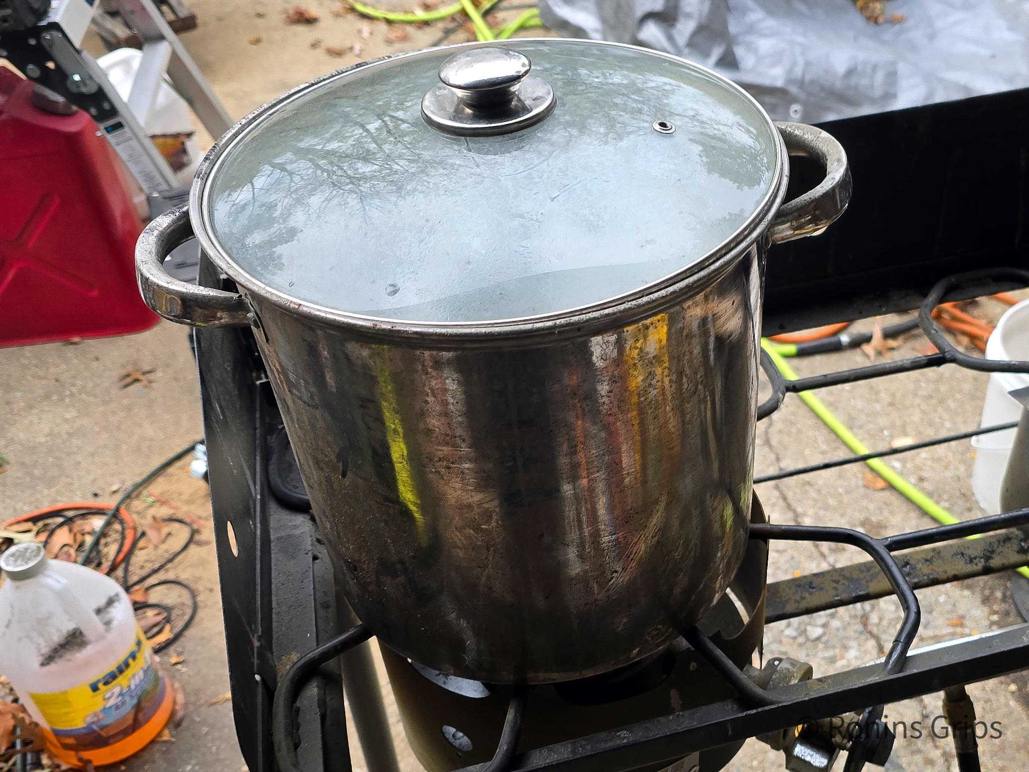
In terms of what I use to hold the parts, the receivers were short so I just used a 12 quart stainless pot I have for that purpose. Note, do not use cookware for this. I’m not joking. I can just imagine some guy thinking “Oh – I’ll just use a pot from the kitchen.” This stuff leaves residues that you should never eat. I have a couple places on the bottom of my pot where I can’t scrape some kind of crust off. My best guess is that the alloy wasn’t consistent but regardlss, do not use pots or other containers from the kitchen. Buy and use dedicated pots, tongs, stainless wire, etc.
By the way, good long stiff BBQ tons are definitely worth it. I have one with plastic jaws and another that is completely stainless. While I was worried at first about scratching the parts, I really haven’t had a problem with that. Amazon has tons of affordable tongs with decent reviews.
In cases where I can’t run a wire through the small parts, I use the strainer/steamer section of my boiler pot or a small kitchen stainless strainer in my big tank if I am using that.
Add acid to water in a stainless pan/pot and heat to 190F – don’t boil and waste it – if it does boil or simmer, it’s not the end of the world and a lid can help reduce evaporative loss. I use a baking thermometer clipped to the side of the pan or my Fluke infrared thermometer.
Spray each wool biscuit with brake cleaner to remove oils and allow each time to dry.
As the solution warms shred the steel wool into the liquid and add the manganese dioxide. When I did these Vmac9 receivers, I found all I had to do was unwind the steel wool rolls, place them in the solution and that was fine.
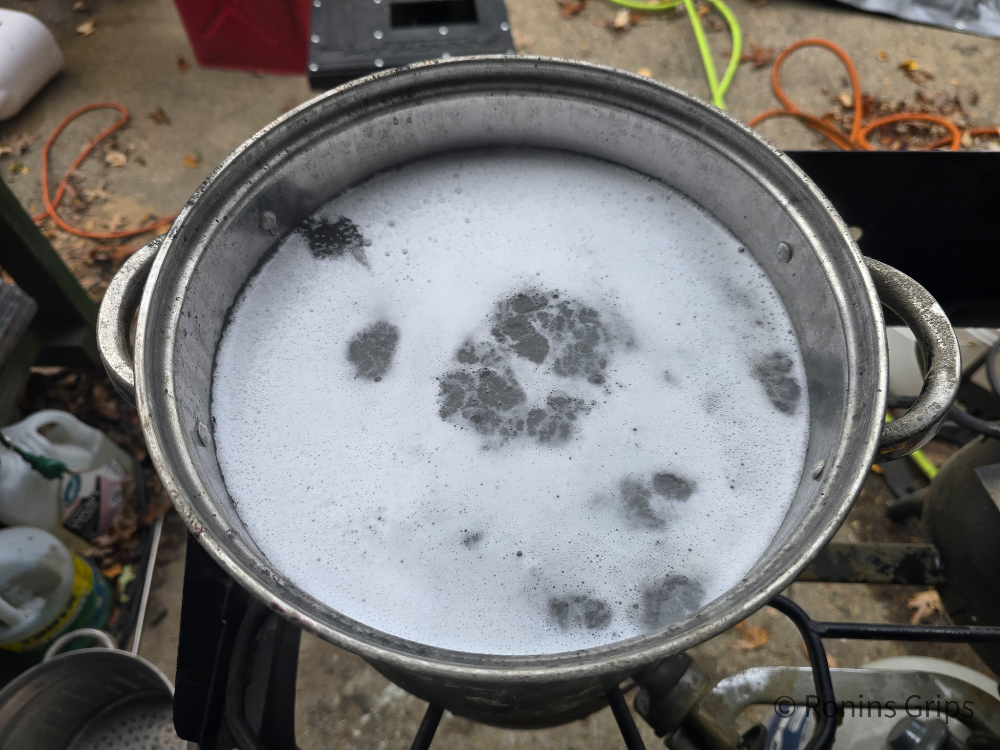
Let the mix simmer and dissolve the steel wool before adding parts. This is key. The solution needs to dissolve the steel to get the process started. I usually, get this started and then get my parts ready. Stir periodically to help things mix.
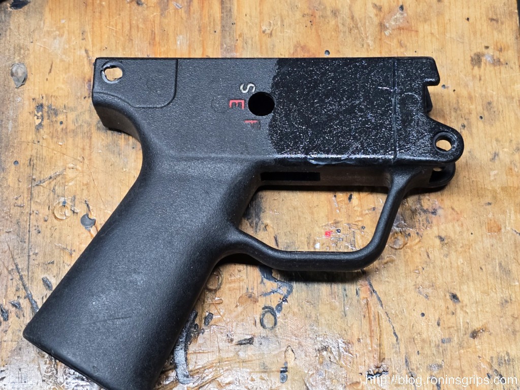
Here, the solution is brewing while I get the receivers ready to go into it. That is a 12 quart stainless pot sitting over one burner of my Camp Chef stove.
I always blast my parts before I parkerize them. I have used sanding mops and other approaches to expose the metal but just find blasting the best for a consistently colored surface. Blasting removes the oxides and exposes the bare steel. I always do that.
Make sure your parts are very, very clean and degreased — only handle with rubber gloves after they are cleaned or oils from your skin can mess things up.
Before you put your parts in, stir the solution to keep the manganese dioxide suspended. I do not stir once the parts are in the pot or tank.
You can suspend your parts in the liquid with stainless wire. Leave them until the fizzing stops or about 30-45 minutes. The time varies depending on many factors including the solution itself and the heat.
All three receivers were in there and I let them simmer for about 45 minutes.Here they are fresh from the pot. I use kitchen tons to pull them out because they are hot. I also am wearing nitrile gloves and eye protection. Again, do this outdoors. You don’t want this condensing on exposed steel in your shop and case rusting.
Rinse the parts with boiling water thoroughly to remove the acid. I have never found the need to do more than thoroughly hose down the parts. I literally use a garden hose.
Spray parts with WD40 to get the water away from the steel.
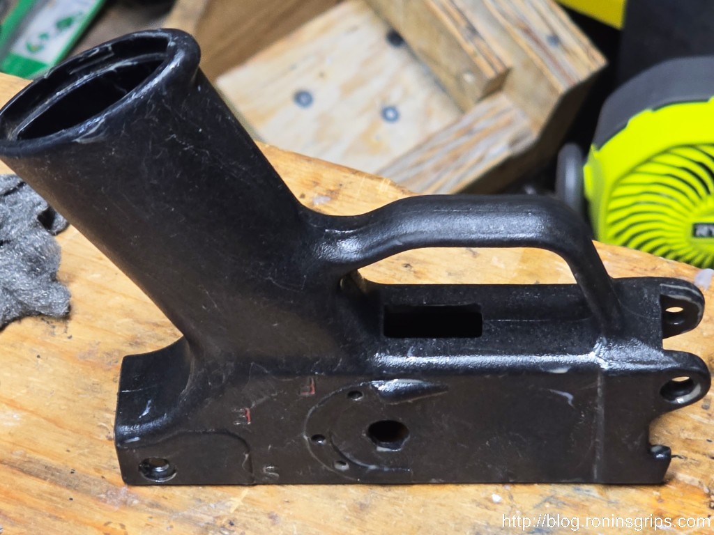
Here are all three receivers soaked in WD-40 after being hosed down. I then rubbed them down with 10w30 engine oil.
Wipe down with oil or apply whatever secondary finish you want – don’t do both 🙂 If you are going to apply a finish on top of the parkerized surface, use acetone or brake cleaner to remove any oils and then follow the vendor’s instructions.
Now, you have another option also – After the oil rub, I heated them up to about 125-150F, let them sit for a bit and then rubbed in Sno-Seal boot wax to just really seal things up but also keep the parkerizied look.
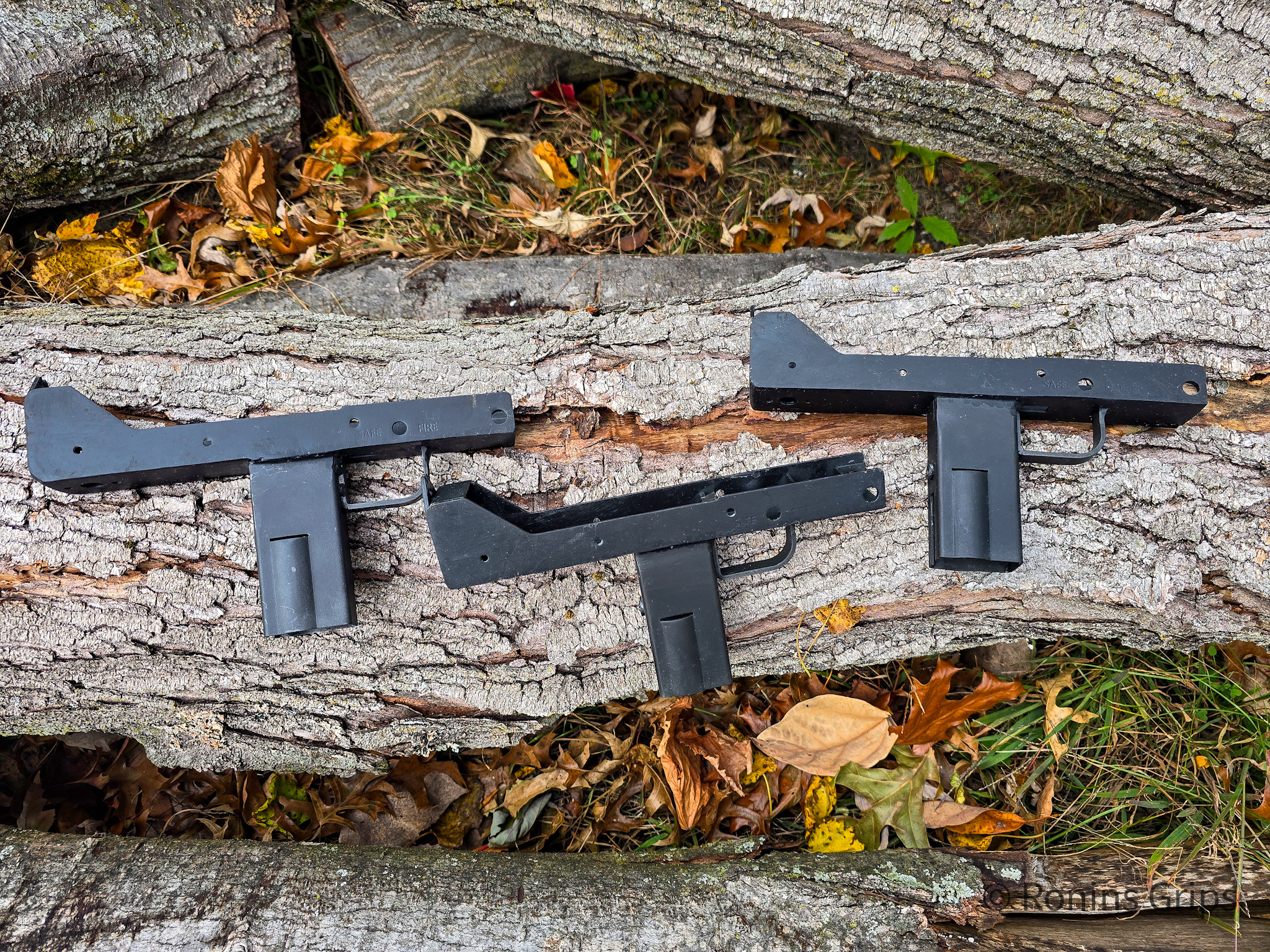
Here’s a view of them together:
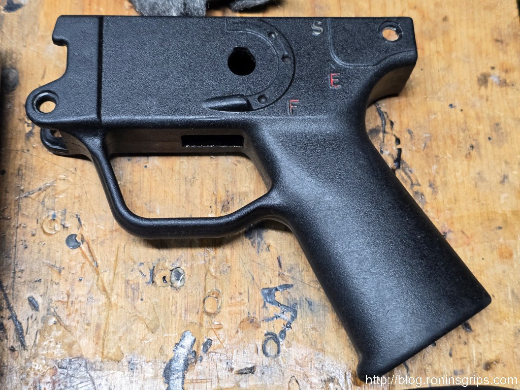
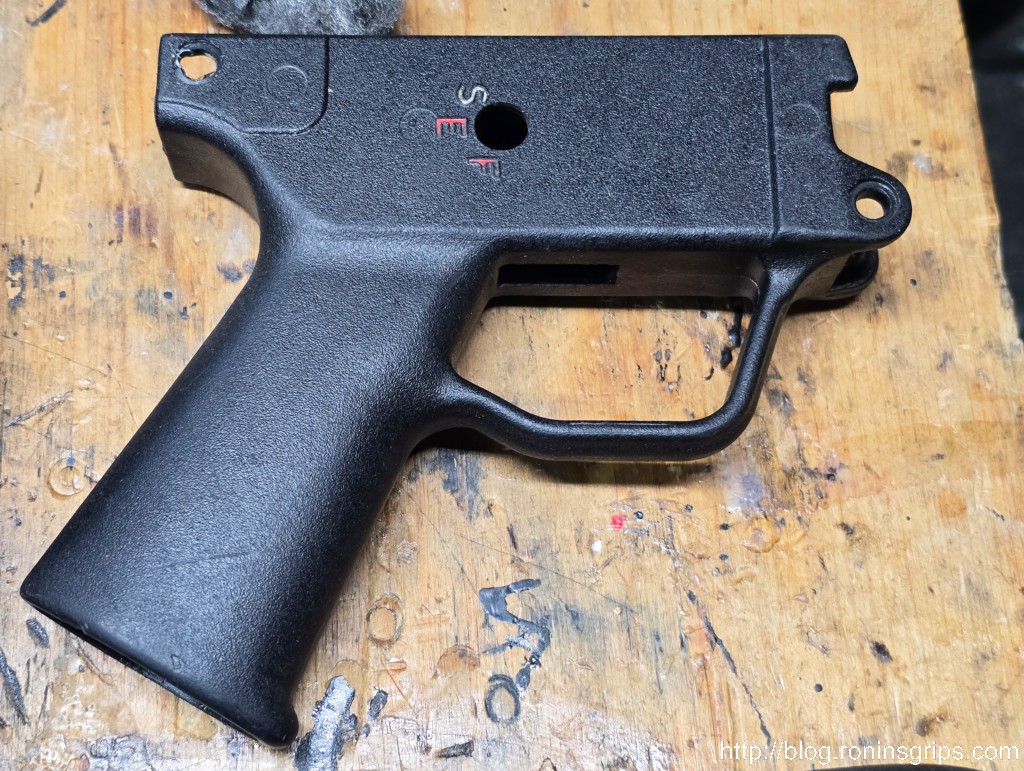
Herre they are ready for assembly. The park is nice and consistent. I did need to redo one of them. There was a spot I didn’t blast enough so the park didn’t take well. I blasted that area and a bit more, cleaned it up and then redid it. I did this right after hosing the part down – that’s when I noticed it.
Summary
You can definitely do a manganese park at home and make your own recipe that is just as dark as what Velocity does. The receipe and process above are affordable, easy and generate great results as evidenced above.
I hope this helps you out.
Note, I have to buy all of my parts – nothing here was paid for by sponsors, etc. I do make a small amount if you click on an ad and buy something but that is it. You’re getting my real opinion on stuff.
Please research and comply with all applicable federal, state and local laws and regulations before you undertake a build of any kind. I am very careful to understand what I must do to legally build pistols and rifles before I begin a project. I am not a lawyer and will not give legal advice. If you decide to build something, you accept all legal and regulatory liability. This post is for informational purposes only. Please be careful and please be legal.
Need to start this post with a reminder to be legal and safe.
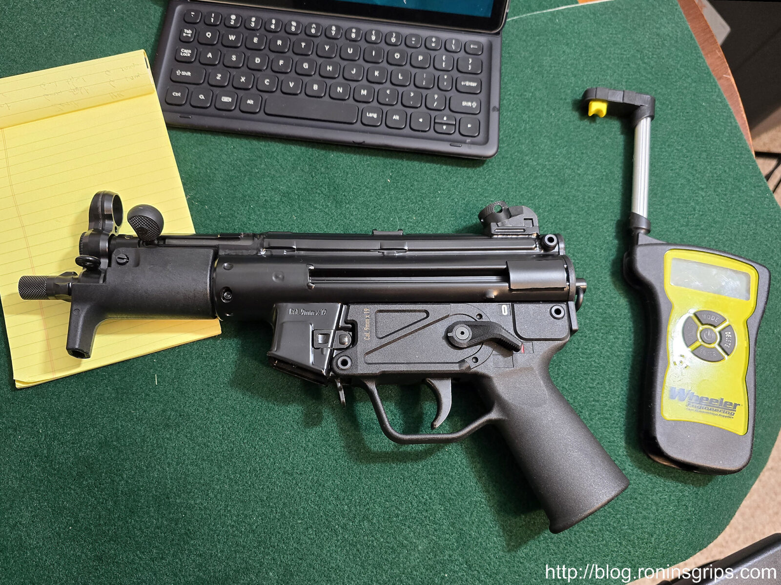
When I was a kid in the 70s and 80s, the Ingram Mac-10 and 11 submachine guns (SMGs) were in tons of TV shows and movies. You could see these iconic blocky little SMGs everywhere with their equally famous two stage suppressors. So, they must have been amazing – right? Well, the truth is their reliability wasn’t that great, they had an insanely high cyclic rate that could dump a 30-32 round mag in about 1.5 seconds and a very short barrel. So, iconic was a big “yes” but effective … well, not so much.
This is the first post of a series wherein your’s truly felt like building something, had a fit of nostalgia and decided to do a MAC-11 in 9mm. This was partly triggered by seeing a lot of really cool printed 3D pistol designs that utilized a MAC-11 upper. I don’t have a 3D printer because I don’t have time to learn one and my wife also told me in no uncertain terms that I was not to buy one … although she may forget this one day 🙂 If you are into 3D printing, search for “MacDaddy 3D Print” and you’ll find the many variations of it.
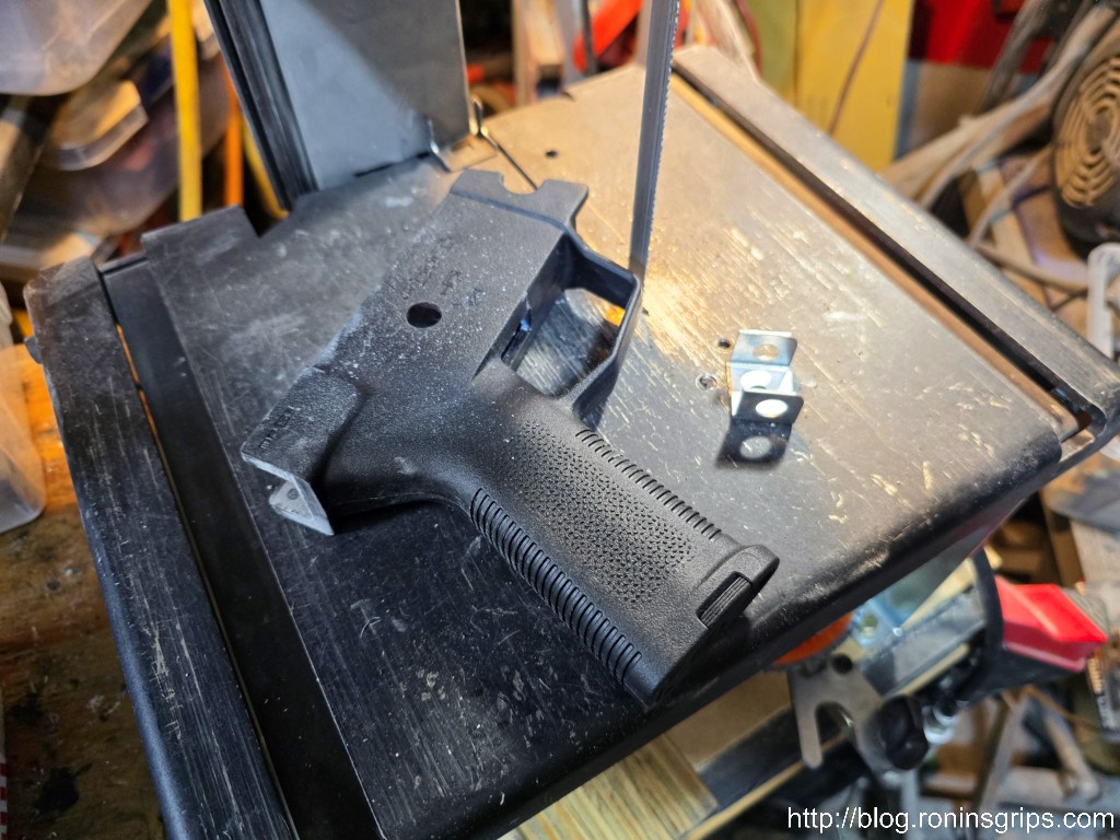
So, on a whim, I googled Mac-11 kits one day and found receiver options that could be bent from a flat or welded together. I didn’t feel like either buying a flat bending jig or making one but I can weld somewhat. If you know the slam “he’s a grinder, not a welder” – that’s me. I’m marginal with a welder but let me assure you, I know how to sand. Thousands of grips and handguards later, I absolutely know how to sand.
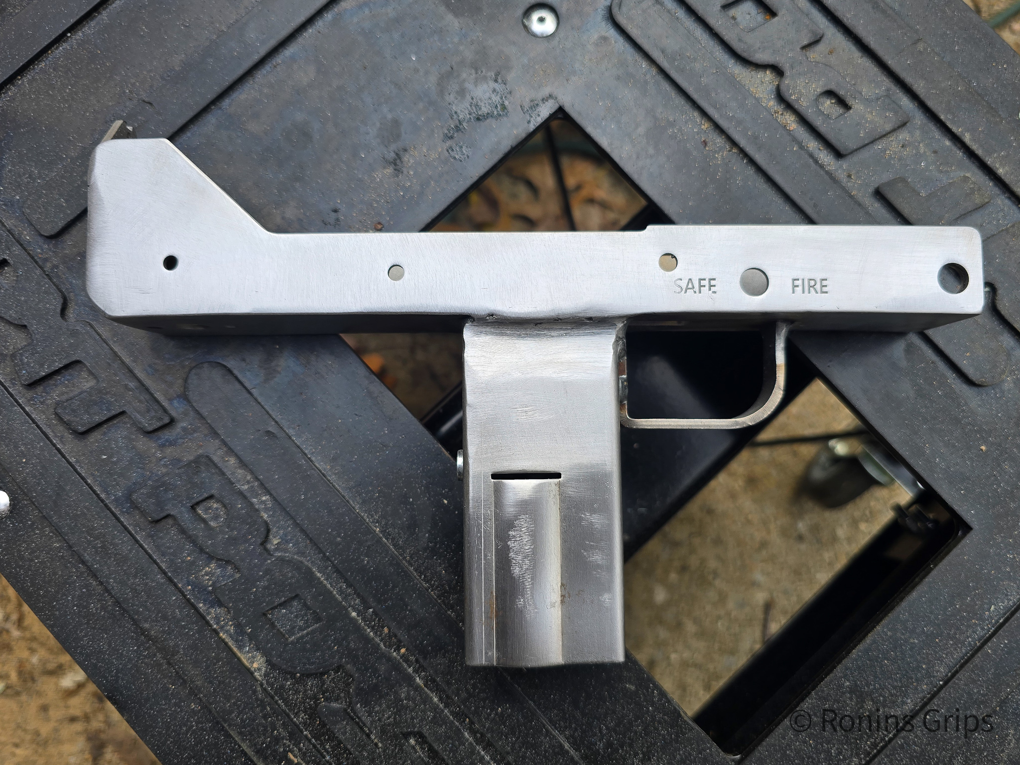
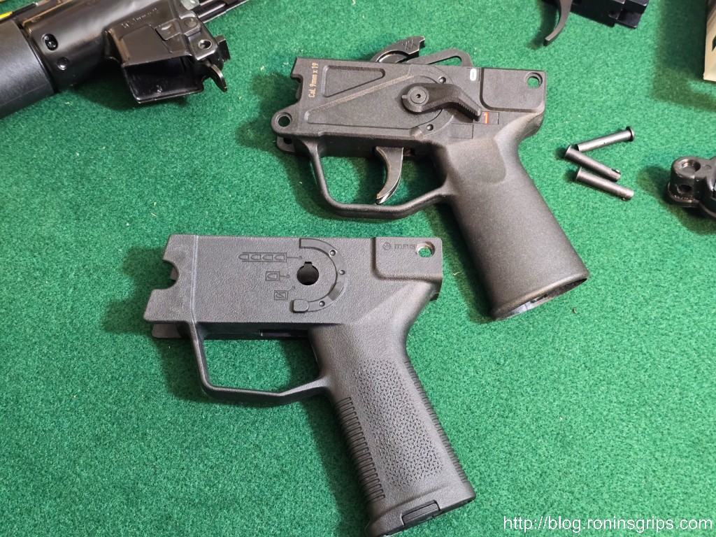
Now you have two options on the side plates – when you buy the kit, Velocity gives you a complete set of prints so you can make your own or you can buy the plates already cut and ready to go from 2D3Dlaser.com. I thought about building them but didn’t really feel like it and the 2D3D plates had really good reviews so I went with them — and I’ll tell you right now they are nicely done.
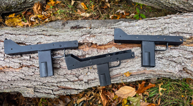
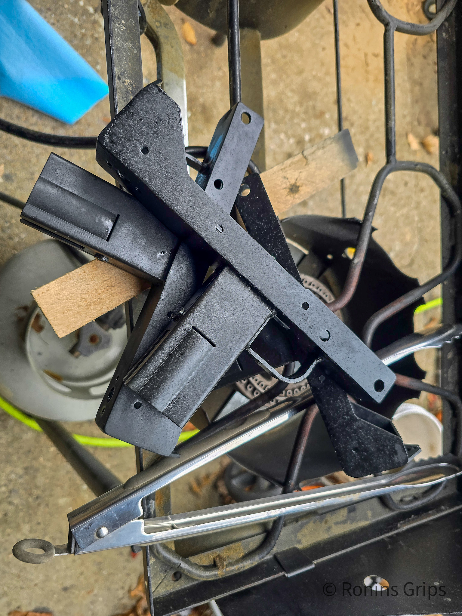
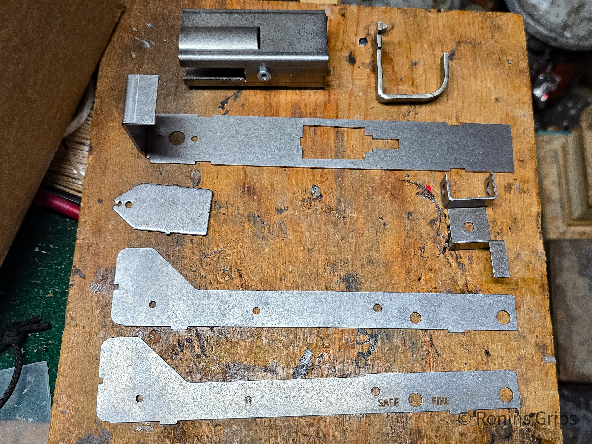
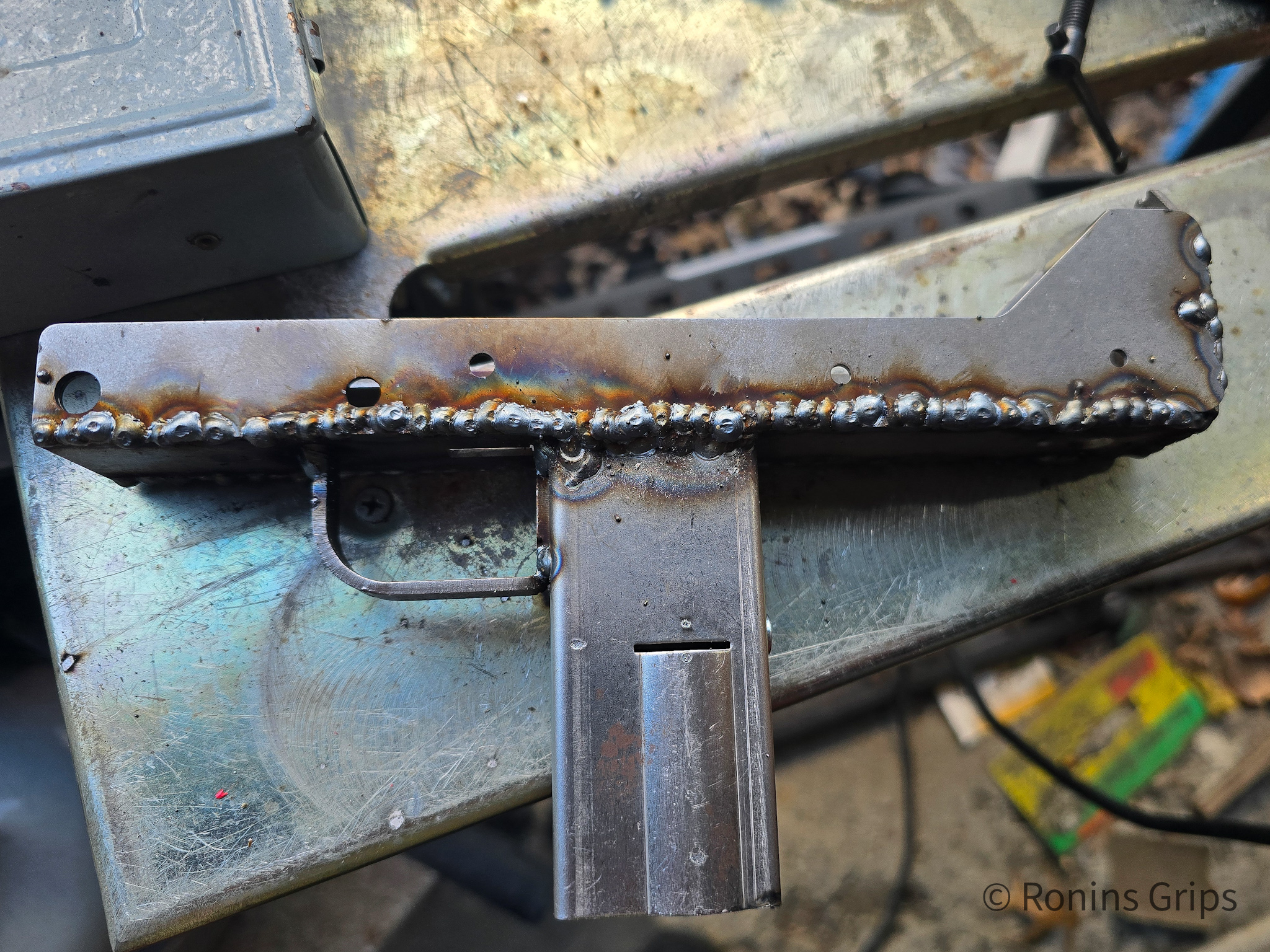
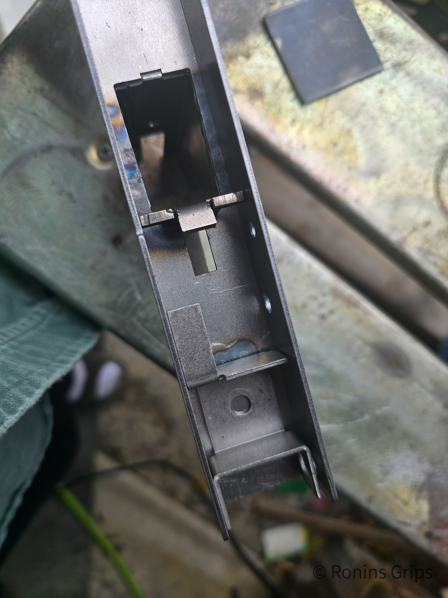
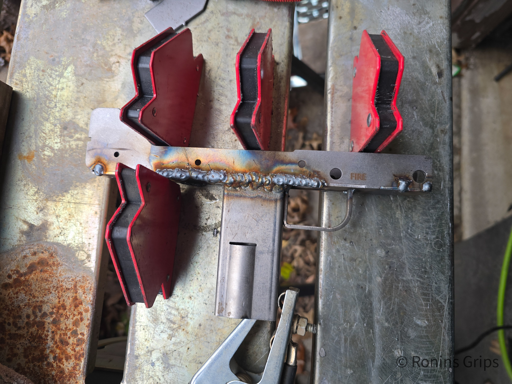
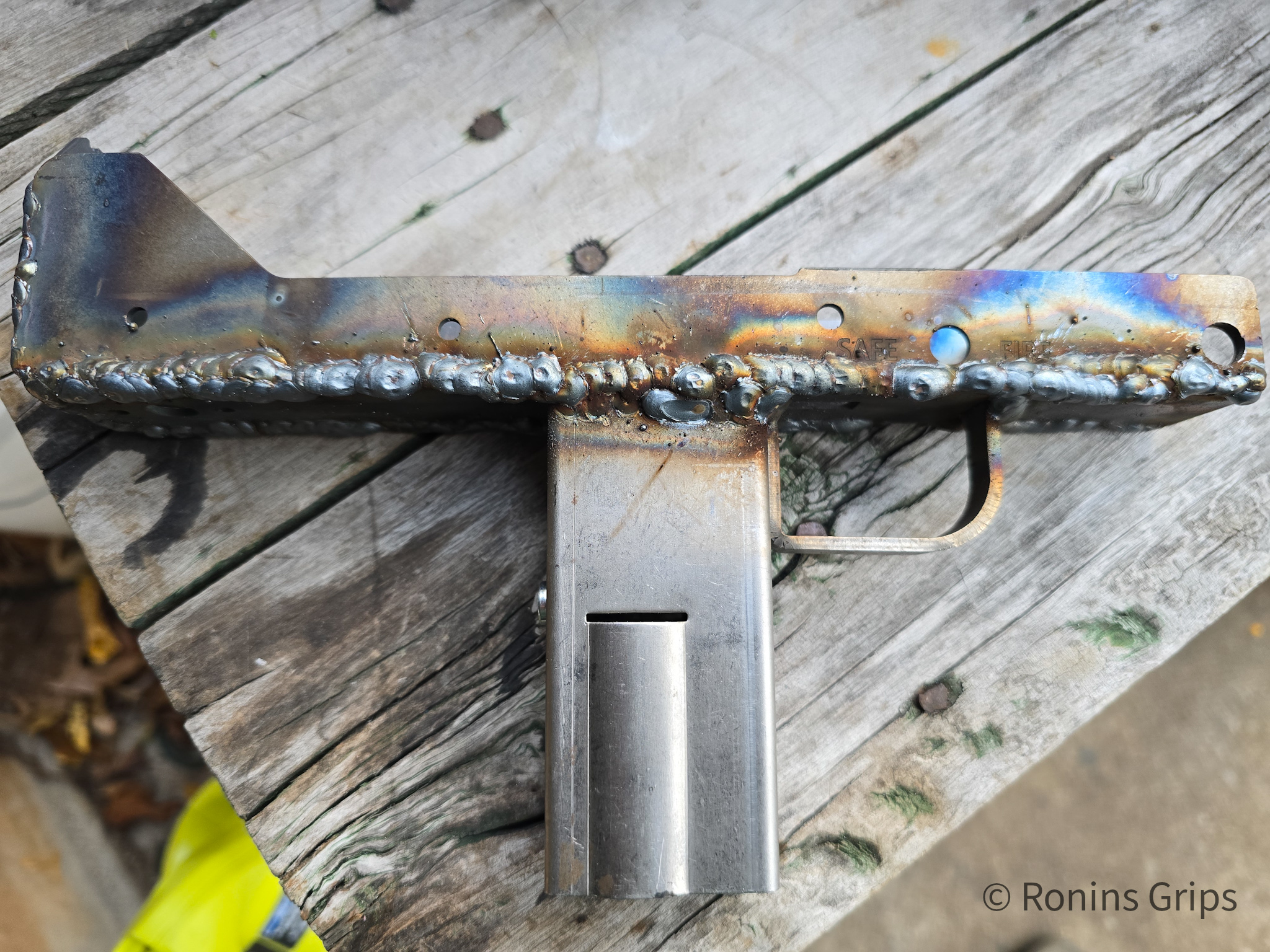
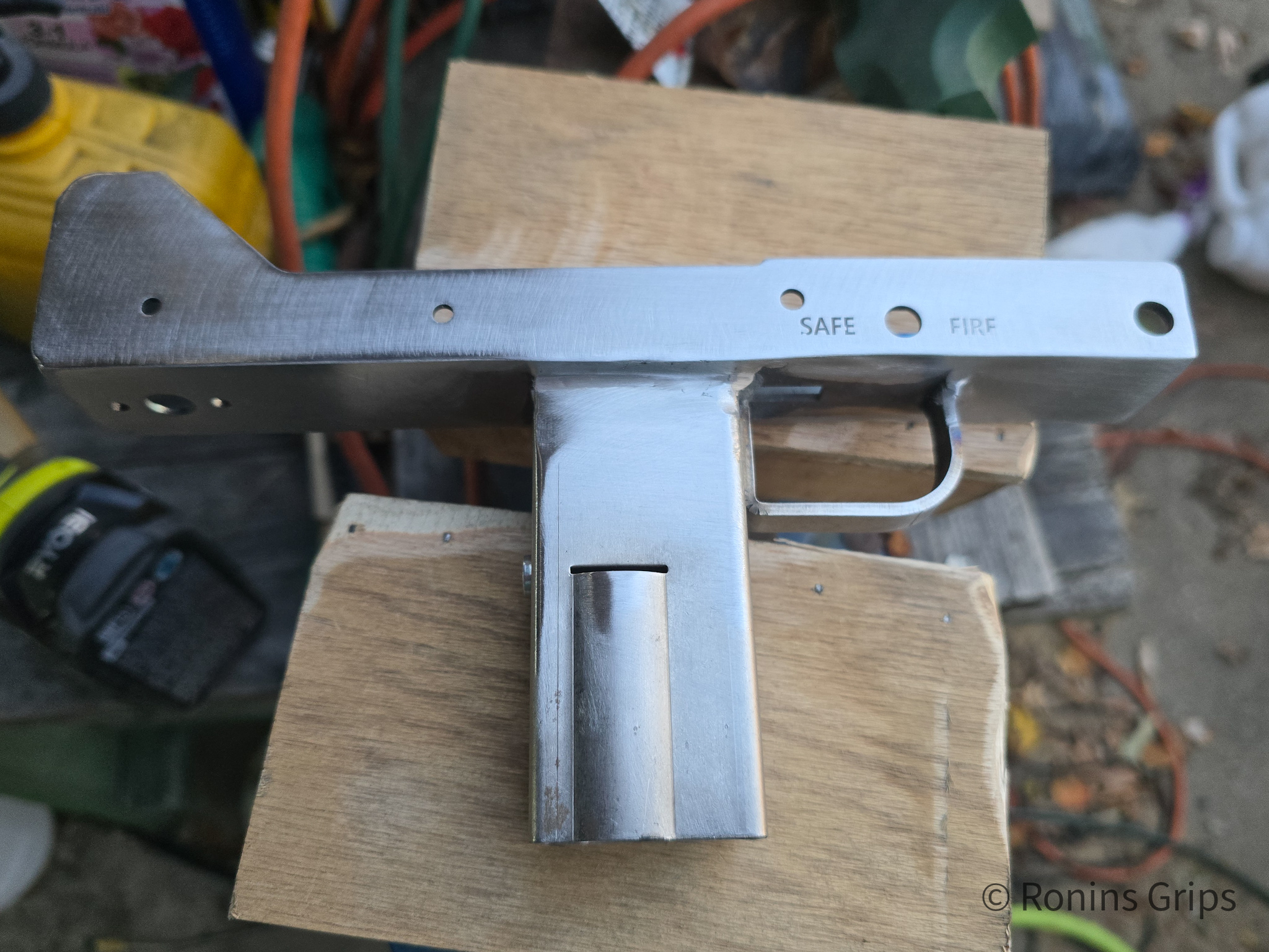
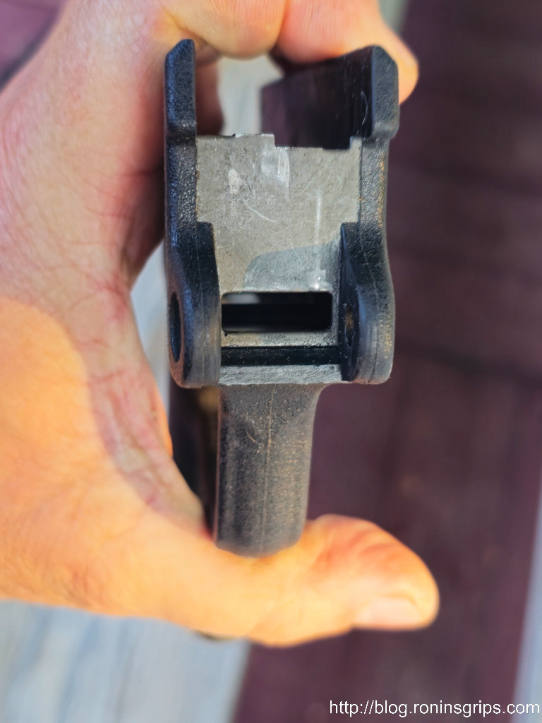
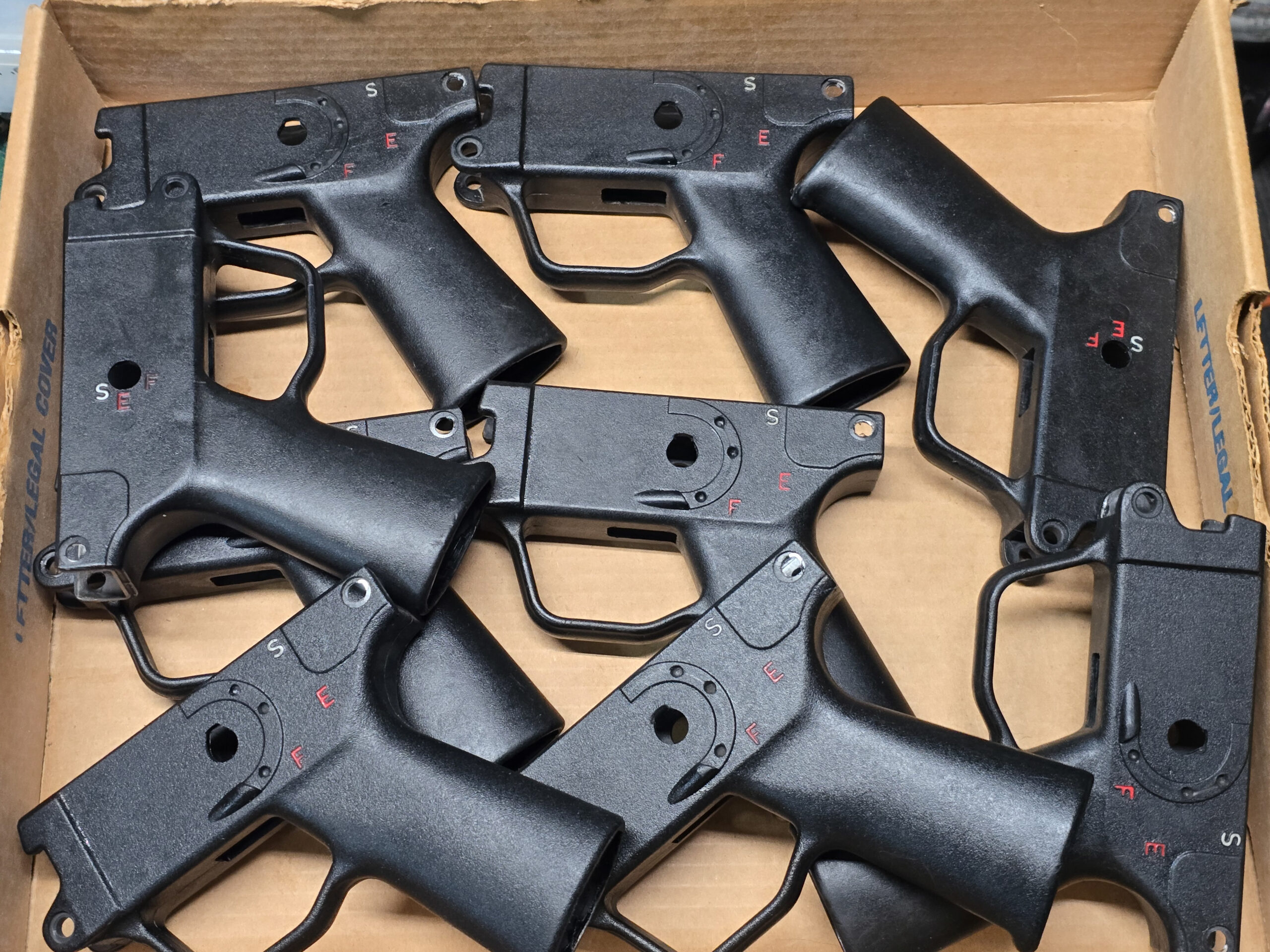
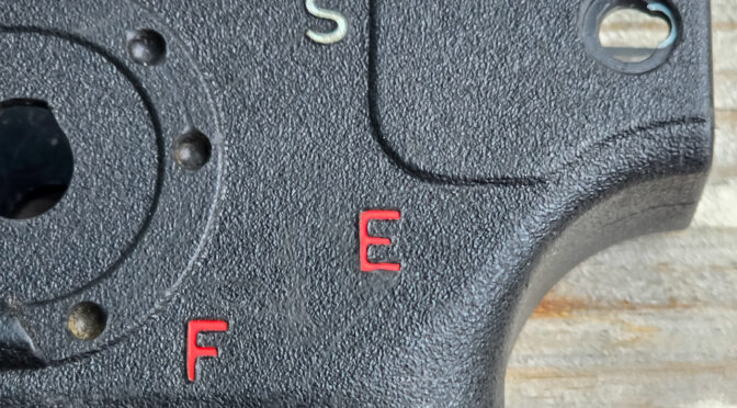
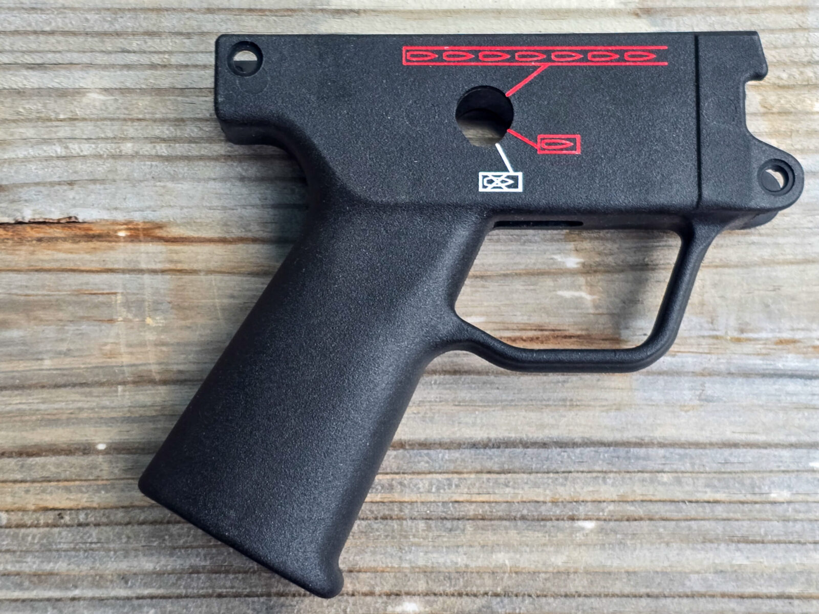
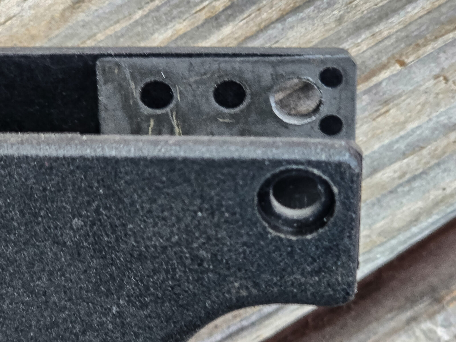
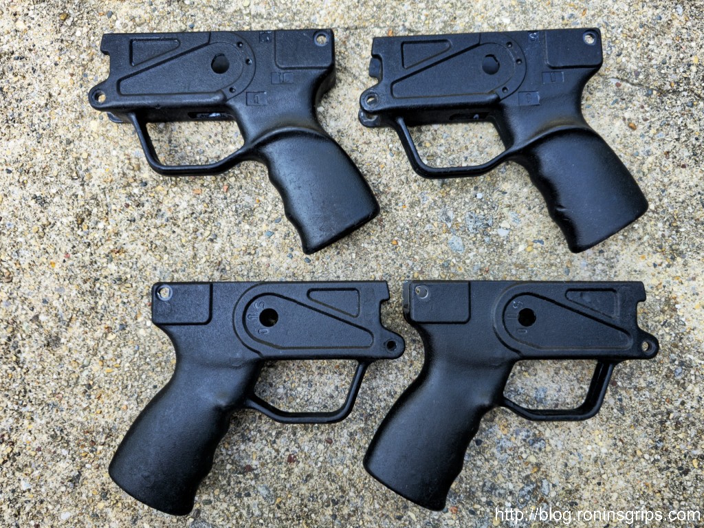
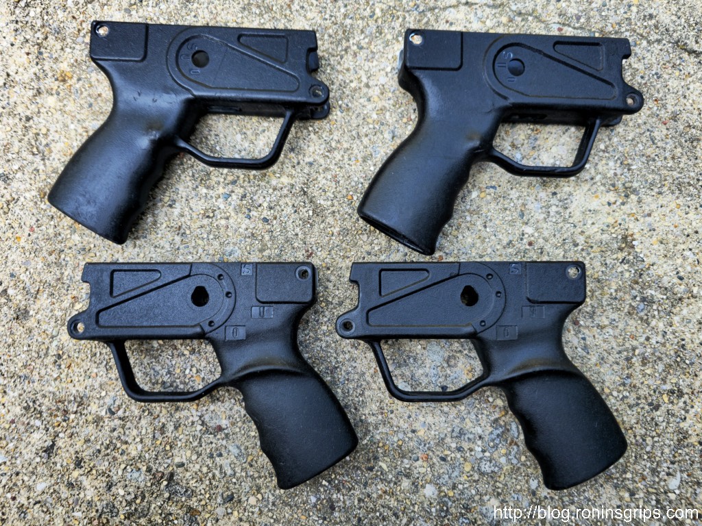
This photo has all of the parts you will weld together. Surprisingly, they are all 14 gauge cold roll steel (so were the originals). Top left is the mag well/grip assembly and to the right of it is trigger guard. The odd flare that sticks up at the back is the bullet guide. Under them is the center section. Under that to the left is the rear sight plate, and to the right of that is the front takedown pin reinforcement. It actually should be turned to the right so the holes you see on the top “U” line up with the holes in the side plates. Under those two is the left side plate – you can tell because it goes straight across the top. Finally, below that is the right plate. I paid 2D3D to print SAFE and FIRE and the selector plus you can see the small depression that aligns with the bolt carrier face and ejection port of the upper. See all of the cutouts on the center section and tabs on the other parts? Those help you align the parts.
You need a welder
First off, you need a welder that can handle 14 gauge sheet metal. I like using a MIG welder with a 75 % Argon / 25% CO2 gas – this is often referred to as “C25 gas” due to the ratio. This can generate very clean welds. The cheap flux core MIGs will work but they have a chemical known as “flux” inside the hollow steel tube that is melting to shield the weld from the atmosphere and it splatters everywhere requiring more clean up.
The best welder you can use is a TIG – those things can generate beautiful welds and there are cost effective entry level welders but they always must have a shielding gas – usually of 100% argon. I spent a bunch of money on a really nice TIG and couldn’t use it because my hands shake too much – I have what is called a “hereditary tremor” and fine motor work like dabbing a welding rod into a weld pool just isn’t something I can do no matter how well my arms and hands are supported.
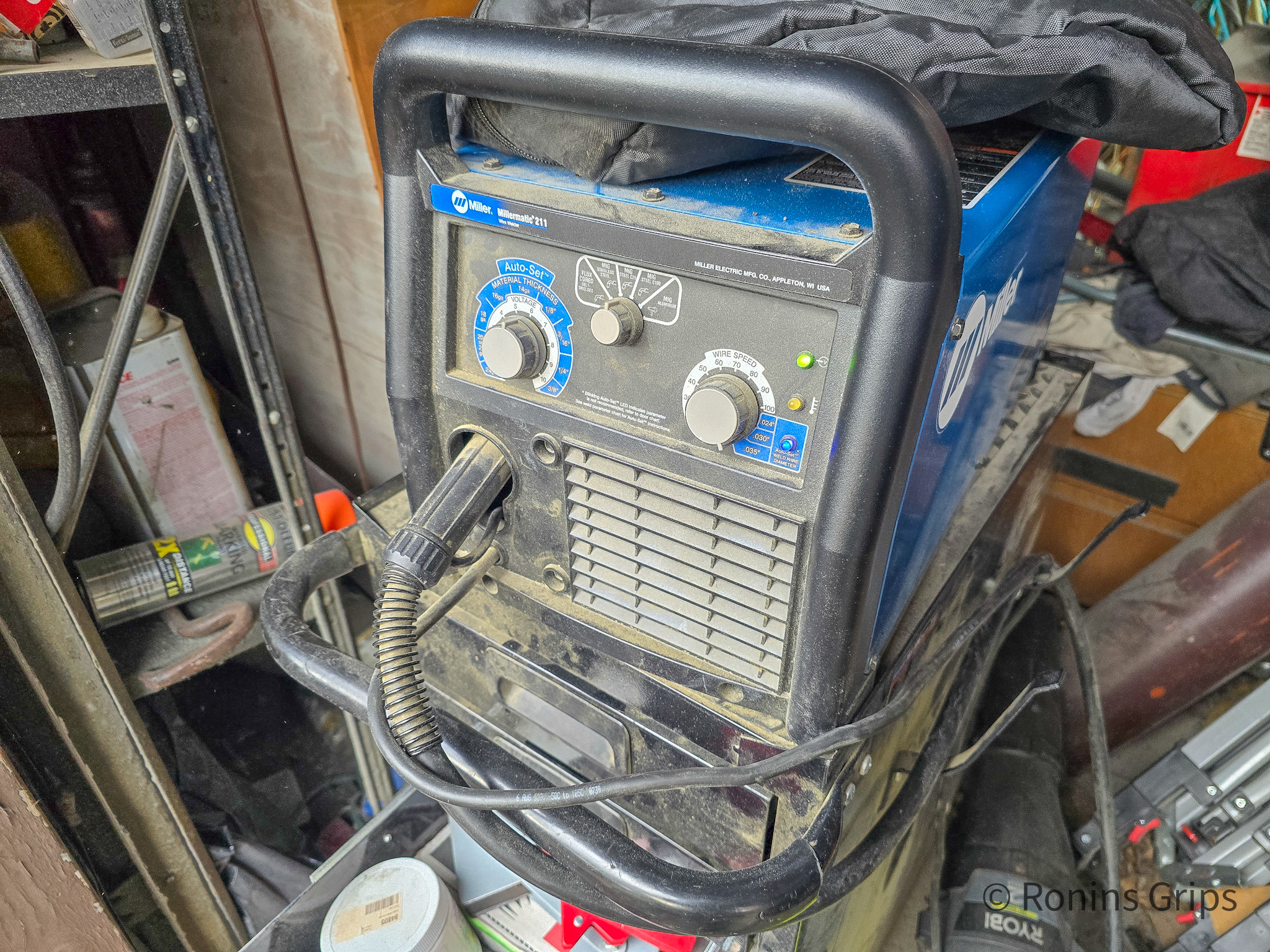
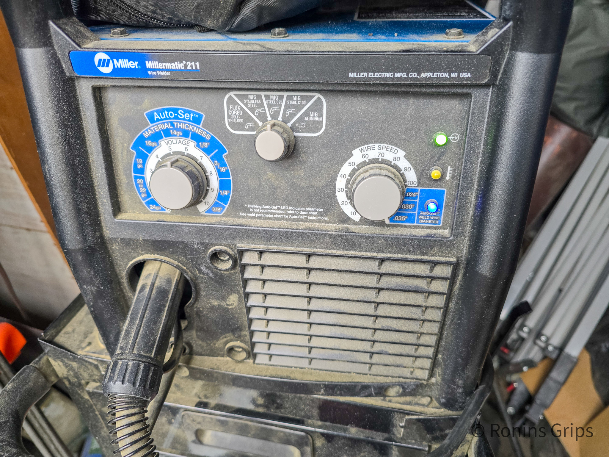
I got by with a cheap Harbor Freight welder for years. When I decided to get a better welder with more depth and a longer duty cycle, the difference was night and day. Most of the time I am fabricating/repairing pieces of steel ranging from 1/8: to 3/8″ thick. I also have found that cheap wire is messier than good wire. I’m running Lincoln 0.035″ diameter ER70S6 wire.This is two parts of the test coupons I bought from Amazon. They give you a bunch of test areas with the pieces they send you and it’s worth it – unless you just happen to have scrap 14 gauge cold roll steel laying around.Welding is not the same as gluing. Technically you are doing fusion welding. The filler metal being introduced is molten and fuses the two metal pieces together., You don’t want the weld to be superficial or so hot that the steel is running/flowing away either. I did this test coupon and tried as hard as I could to separate it or bend it and I couldn’t. If it had pulled apart or broken easily then I would have known I needed to adjust my welder – probably by dialing up the heat. My point is that the weld fuses the pieces together and then you can sand the bead down if you want to. My beads always look like crap so I always sand them down with a grinder or flap sander.The Millermatic 211 MIG welder can automate some of the settings. In the top middle, it is set to C25 gas. Note it can use C100 and flux core plus has an aluminum setting. On the bottom right, I can manually set the wire feed speed or just specify the diameter of 0.035″, which I did here. The Autoset Thickness dial on the left lets me control the volts. If you are wondering why volts and not amps are being set, it is because the Millermatic uses an inverter and you adjust the voltage instead for a better arc and uses less power. On the test coupons, I found I got the level of penetration I wanted with the dial closer to 6. The 14 gauge recommended setting is from 5-6.
I really like Miller welders and Lincolns are good too but you are going to pony up money for either one. If you plan on using your welder a lot buy the best you can afford. Thickness, duty cycle and the quality of the weld all depend on the quality of the electronics in the welders.
If you are new to welding get either a 120 or 240 volt MIG welder. MIGs just make life easier as the welder feeds the steel wire into the weld and the wire is the electrode that is conducting electricity and melting. It’s surprisingly straight forward for a person new to welding. You can start with flux but gas is better – some welders can do either and that would give you some flexibility.
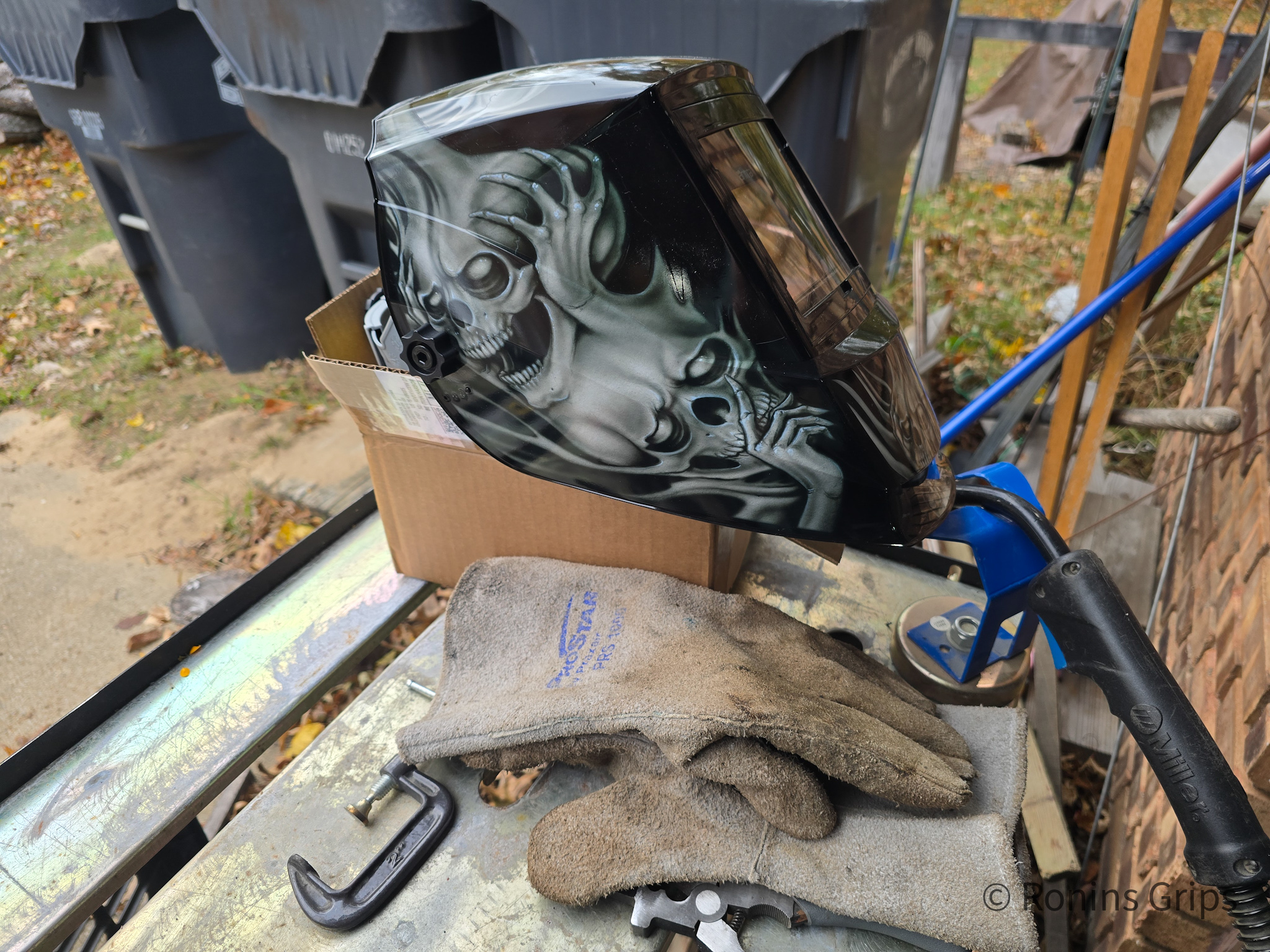
Now one thing that also is critical with a welder is a helmet. The arc from a MIG can really mess up your eyes as it generates quite a bit of UV radiation. I like auto-darkening masks because I can see good and when the arc triggers the lens jumps to the specified level of shielding. I’m currently using an Antra and really like it. A good mask will trigger fast, go darker and usually have both solar and battery backup power. I also keep it in a helmet back to protect it.
By the way, avoid cheap no-name auto darkening helmets. If they are slow to trip and go dark then more damage happens to your eyes. Some guys like permanently shaded helmets so they don’t have to worry about batteries, cumulative effects, etc. They lift their helmet up, position everything and then do a head bob motion so the visor comes down and away they weld. The choice is yours.
This is my third or fourth welding helmet over the years. It is an Antra True Color Wide Shade helmet. Also on table, you can see one of my welding glove sets. The MIG gun is resting in a magnetic clamp holder and it’s all sitting on my Harbor Freight small welding table. I have a big Dewalt welding table for larger jobs.
Cover yourself up
Last welding comment – cover up. There are two reasons for this. First, the UV radiation will give you a really nasty radiation burn that is deeper than a sunburn. I wear a long sleeve shirt and pants. It’s not happened to me (honestly) but I’ve talked to guys who were wearing shorts and welding crouched down and they burned the inside of their thighs so walking absolutely sucked for them – two guys and they both said “I didn’t think I was going to weld long enough for it to matter. It wasn’t me because I own mistakes so others can learn – I sure learned from them.
The second reason to cover up is that welding generates “spatter” – little droplets of steel that can get blown off and cause small burns. Shit happens. I’ve been burned through just about everything at one time or another and being covered up just reduces the odds. Guys who weld a lot will wear a leather apron, jeans and safety boots.
Always wear welding gloves for a boat load of reasons – spatter, protection and insulation from heat as you weld. Gloves also reduce the odds of burning the crap out of yourself when you accidentally grab/catch something hot.
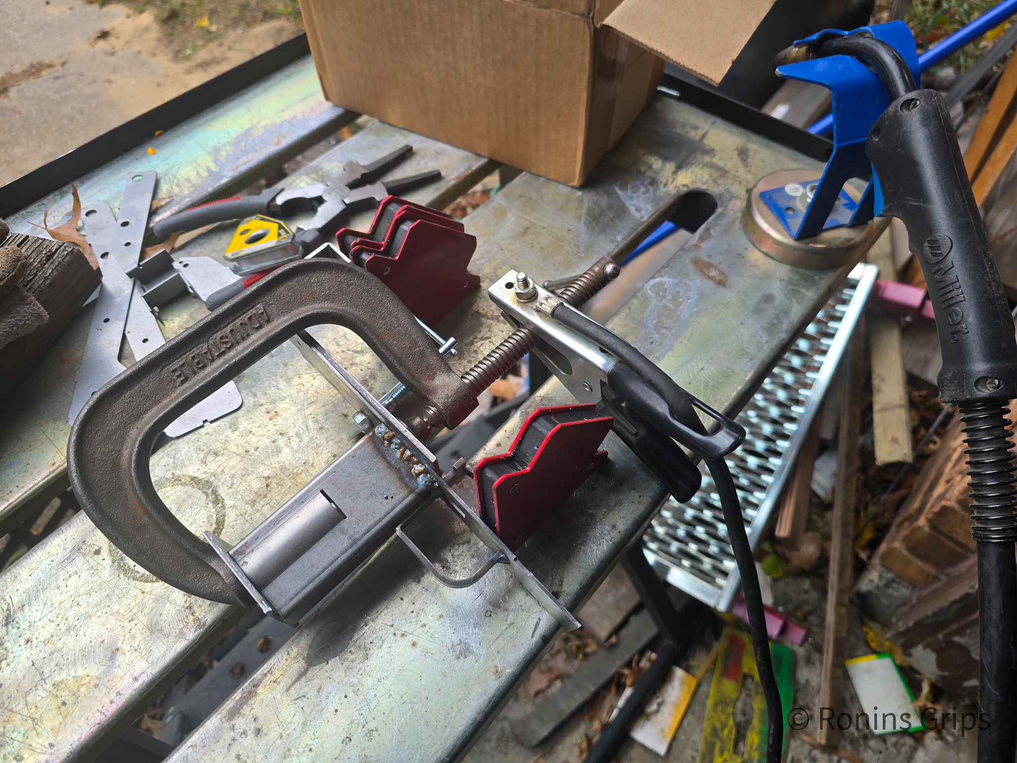
You’ll need a collection of clamps
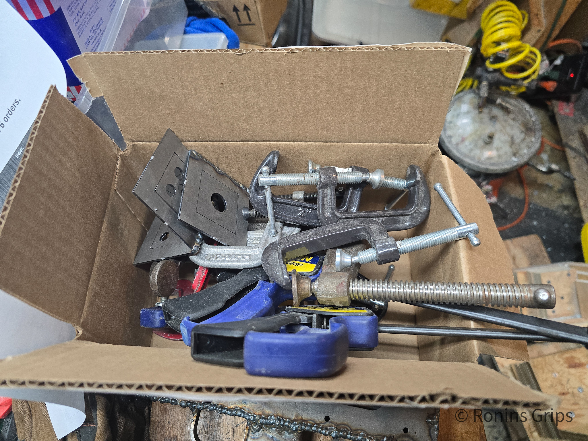
In addition to the welder, you are going to need clamps. How many kind of depends on how you clamp everything together. BTW, plastic clamps can hold stuff but don’t weld anywhere near them or they will melt. There are C-clamp assortments on Amazon.
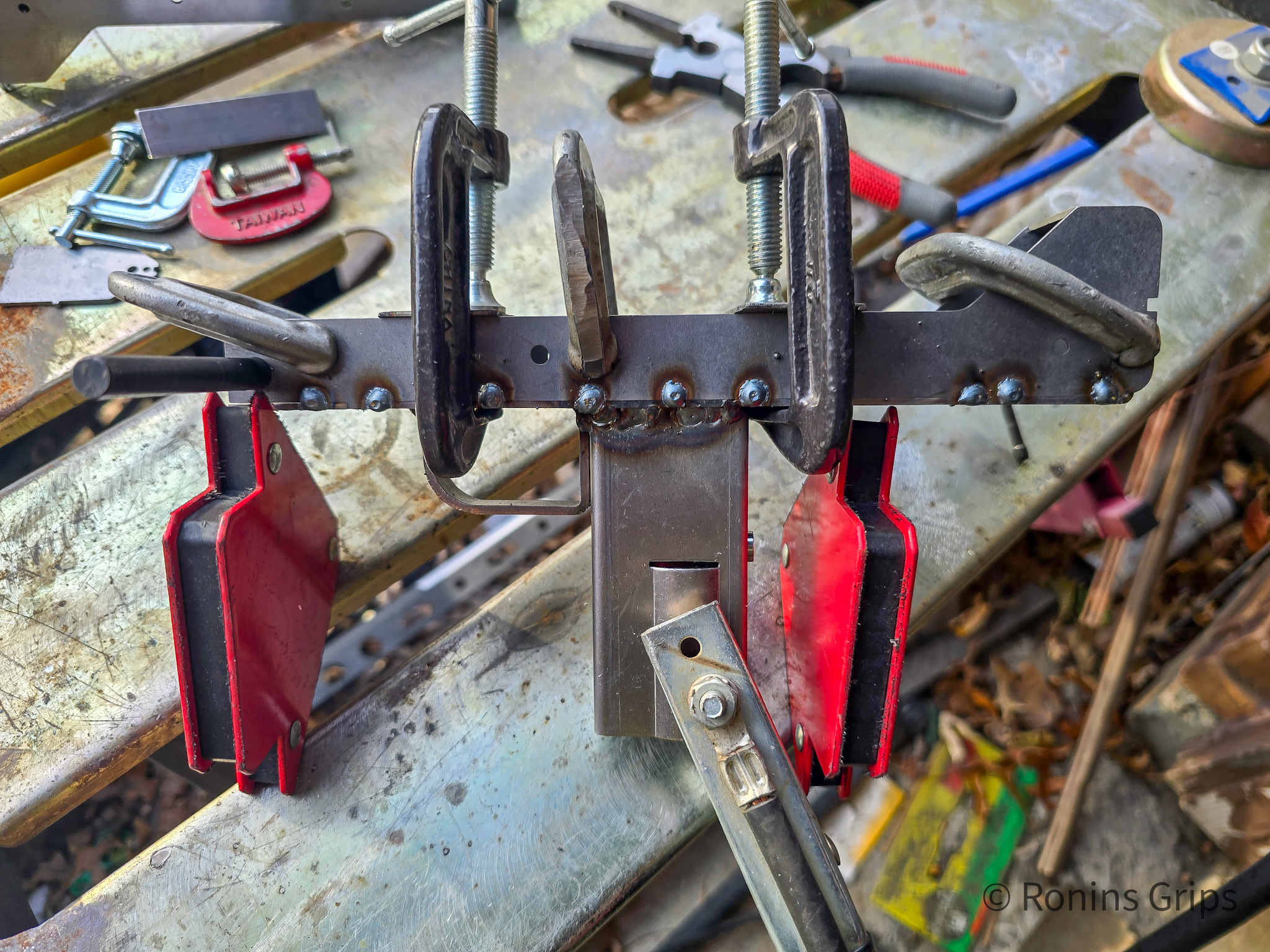
I took a quick photo of a box I had clamps sitting in for this project. I have 3-4x this many clamps.
You’ll see I have a variety of 1″, 1.5″, 2″, and 3″ clamps plus one 6″ clamp for the handle. How many you need of each depends on how you decide to do your welding. A couple of pieces of scrap metal will also help with your clamping so you can apply even pressure.
In general, you need to securely clamp what you are welding so stuff doesn’t move. The better job of clamping you do, the less rework you are going to experience from things shifting.
Various sizes of magnetic welding clamps come in handy too. I have all different sizes ranging from pretty small – maybe 1-2″ and then up to 4-5″. The come in handy for holding work in place and keeping it from sliding around. There are a lot of options on Amazon.
The actual clamping and welding
I planned to do three receivers – two pistols and one rifle. So, I tried welding three different ways:
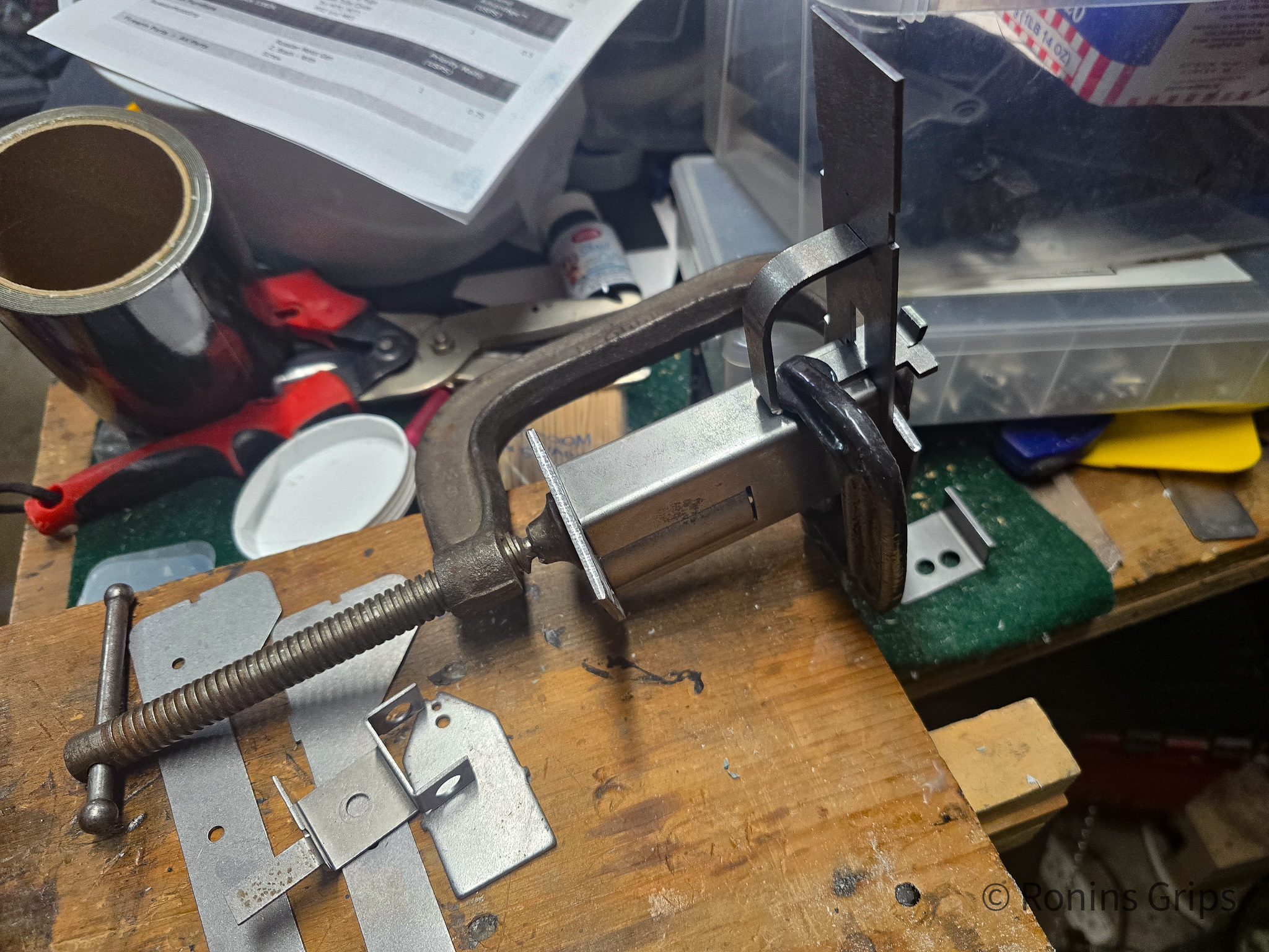
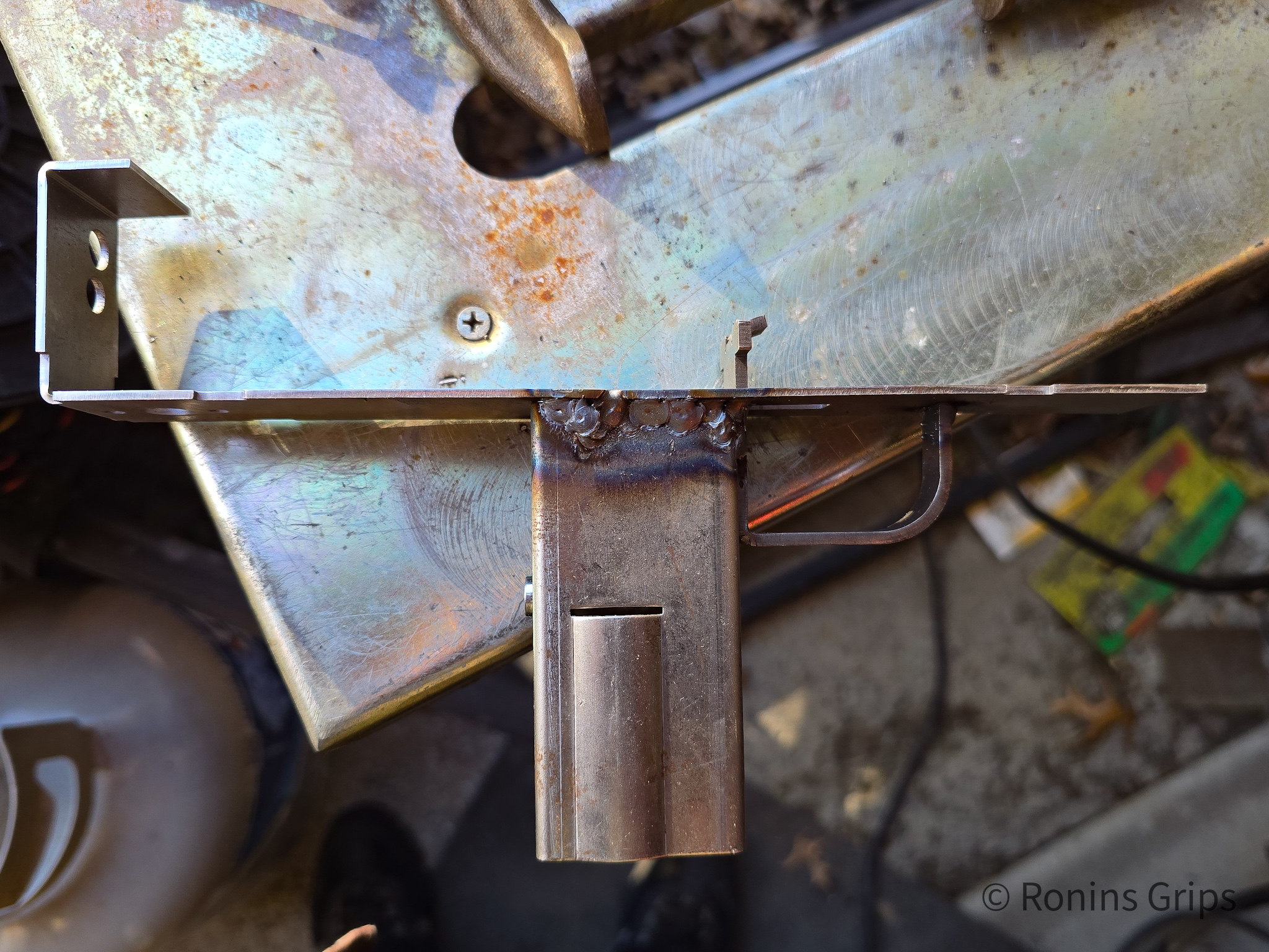
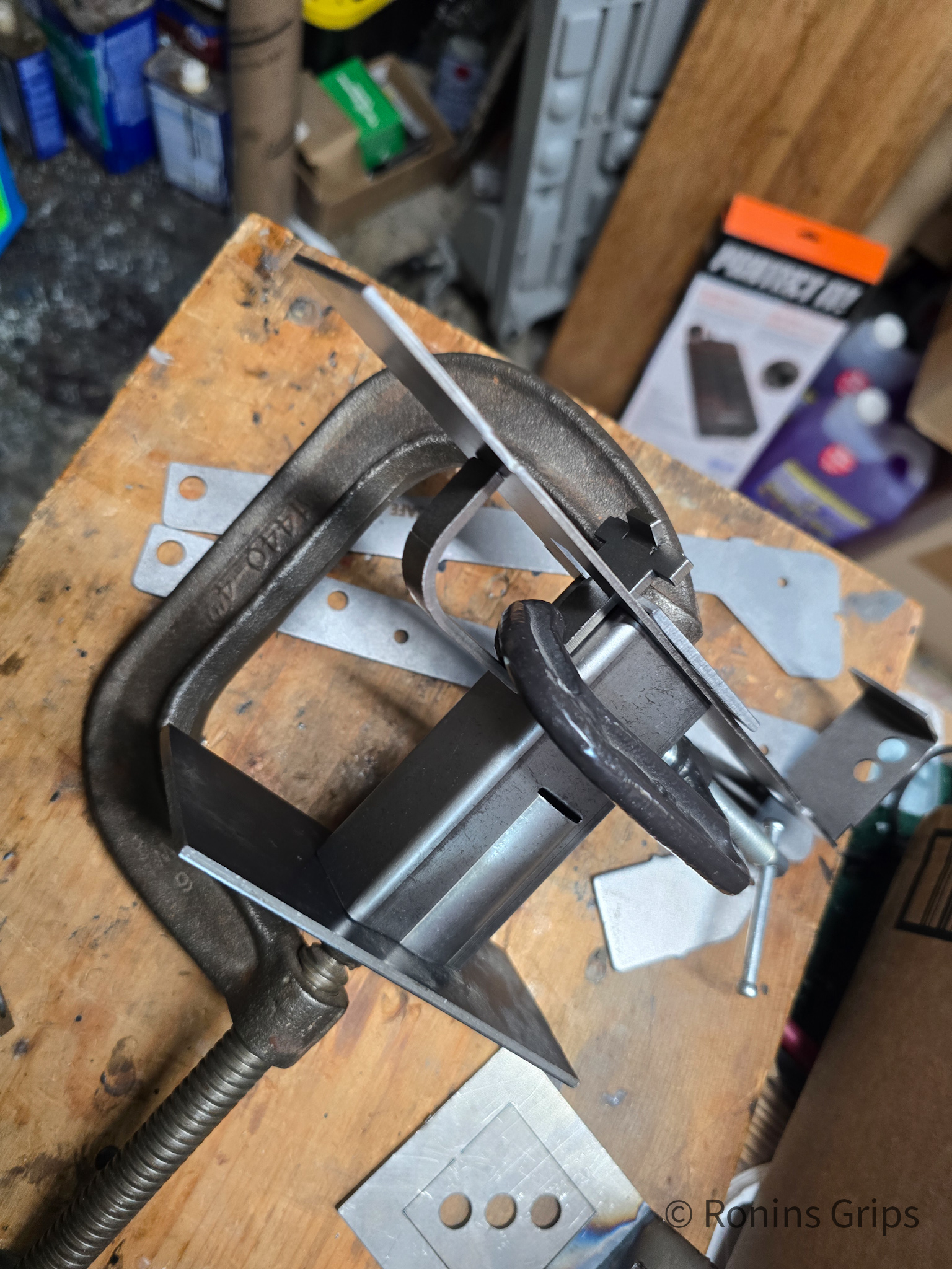
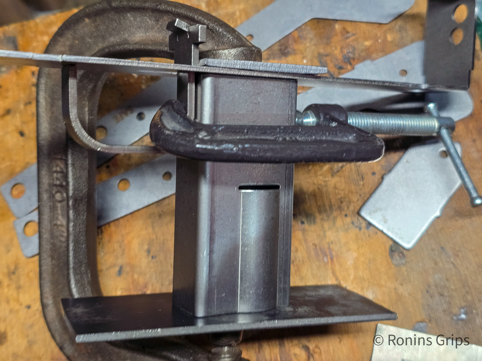
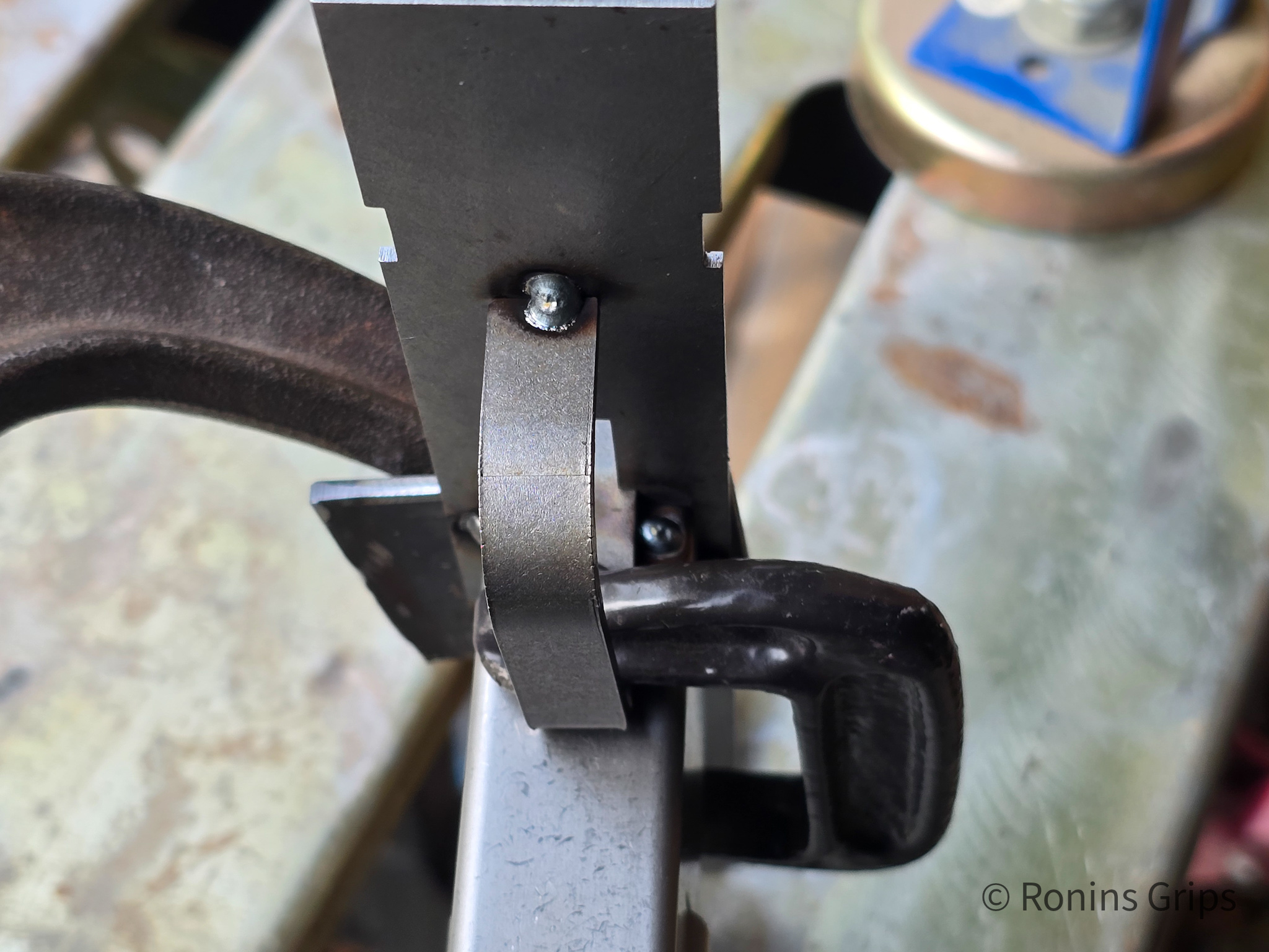
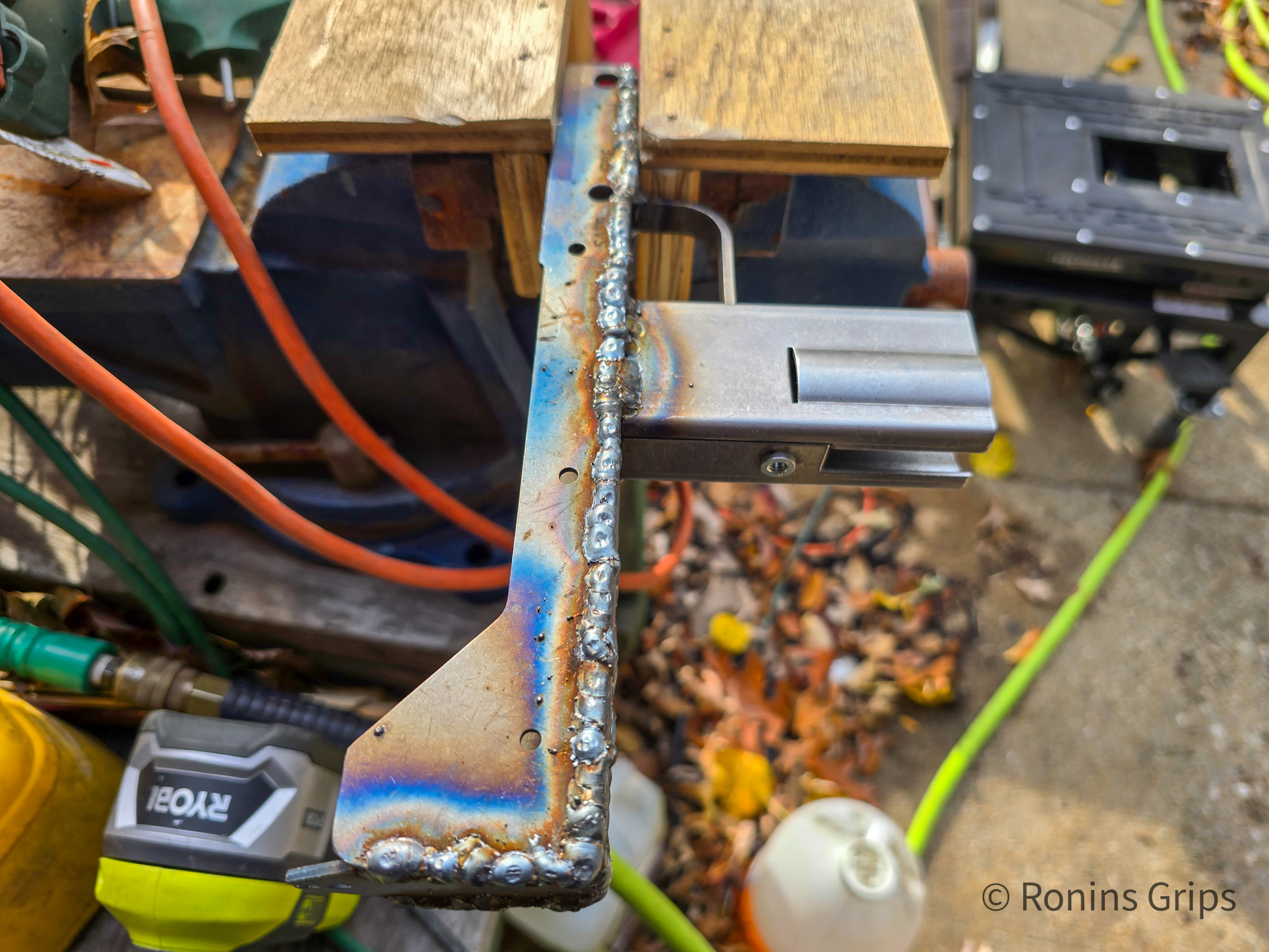
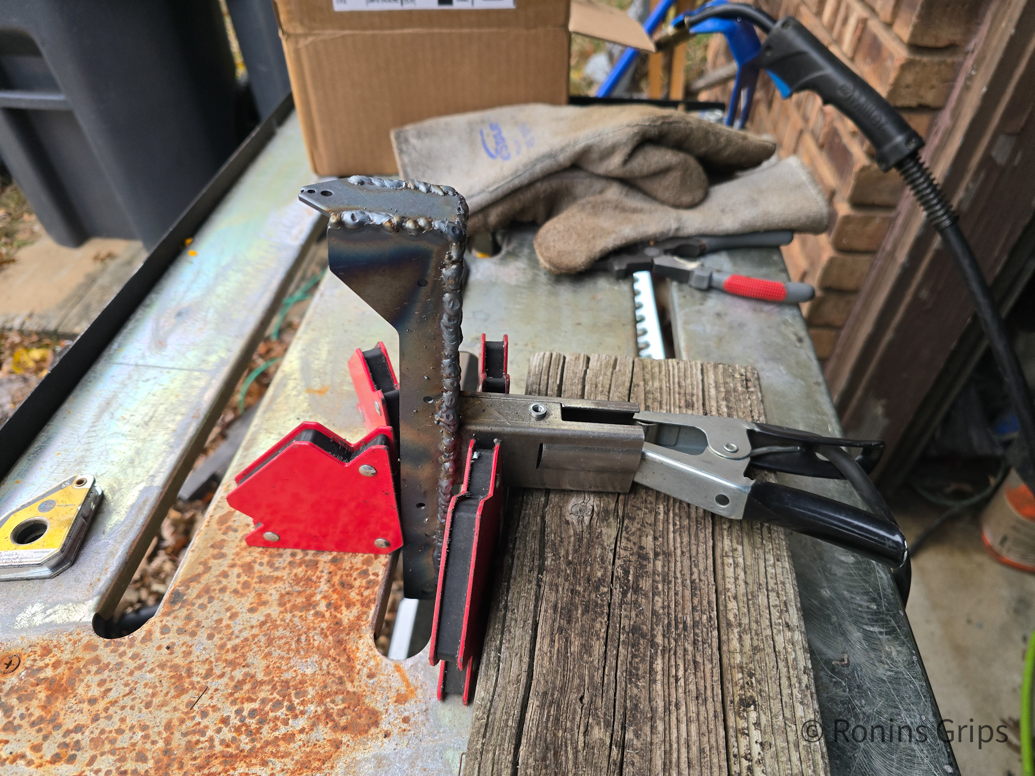
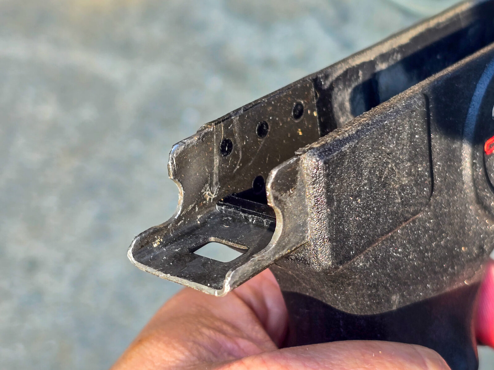
First Receiver: I clamped the grip, trigger guard and center section together, welded them and then used a right angle piece of aluminum to clamp the right side plate into position welded that, did the same for the right side plate and then the center reinforcement plate. Then I welded in the rear sight.
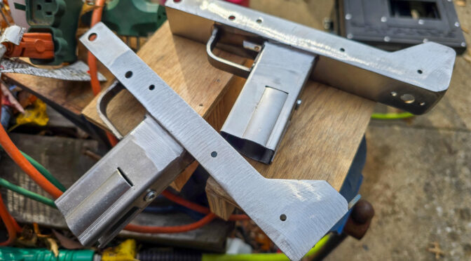
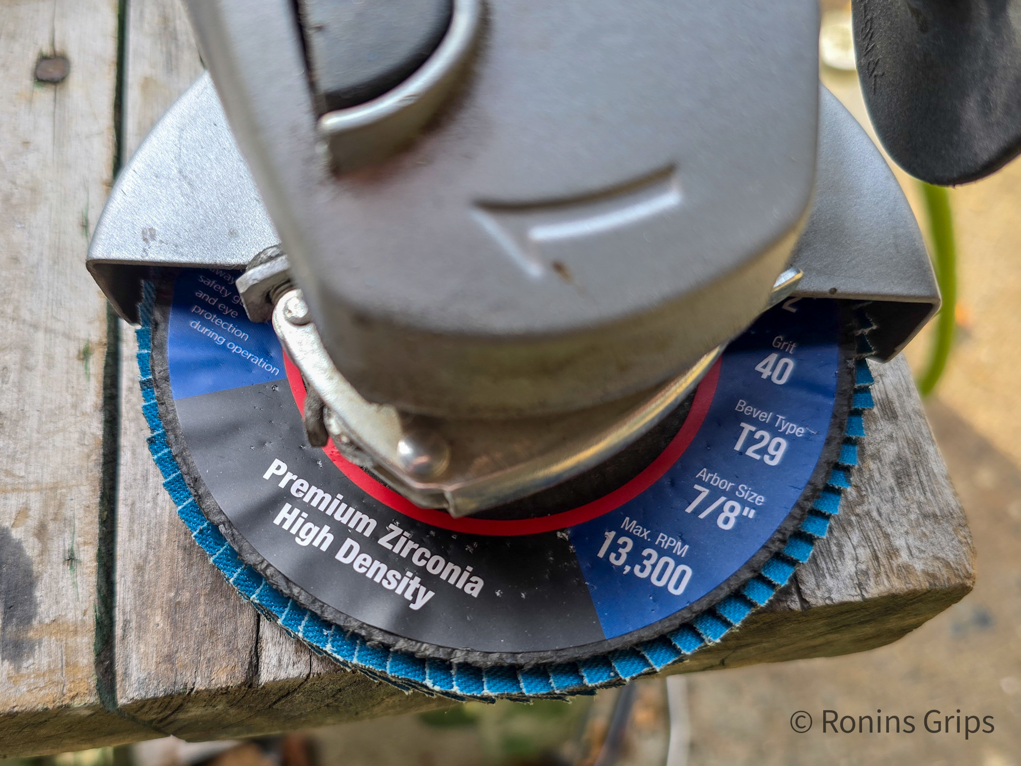
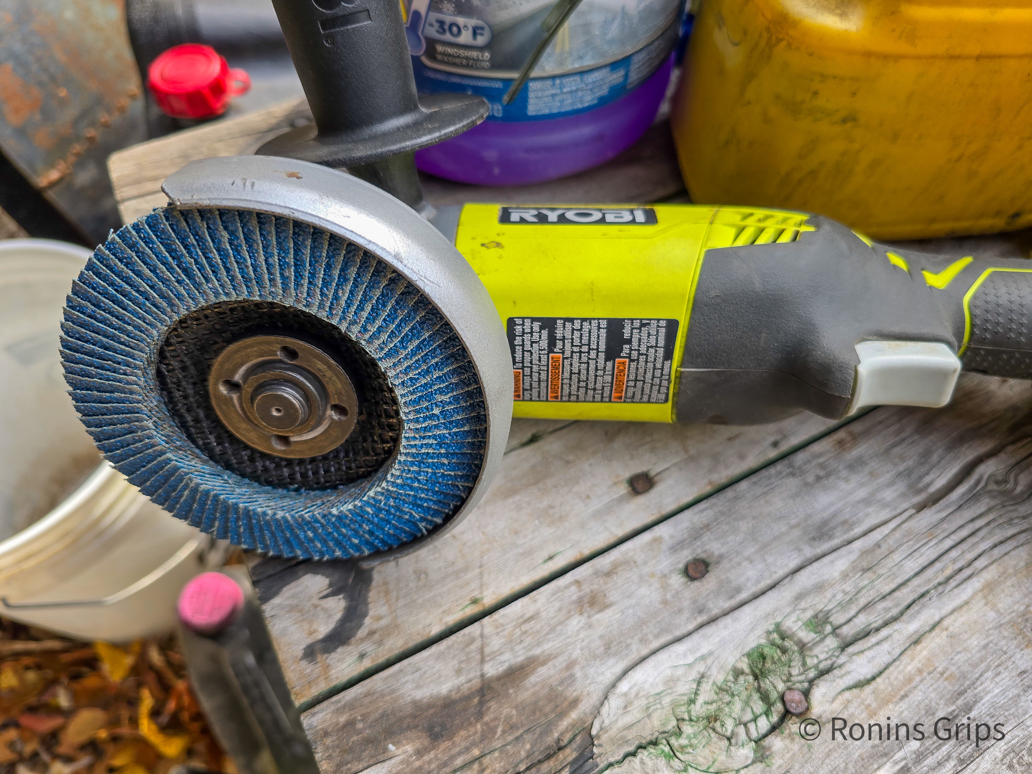
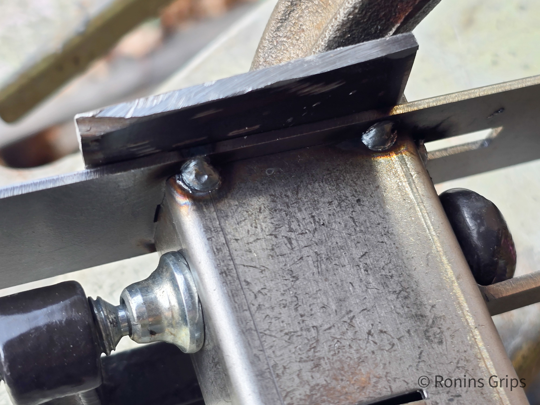
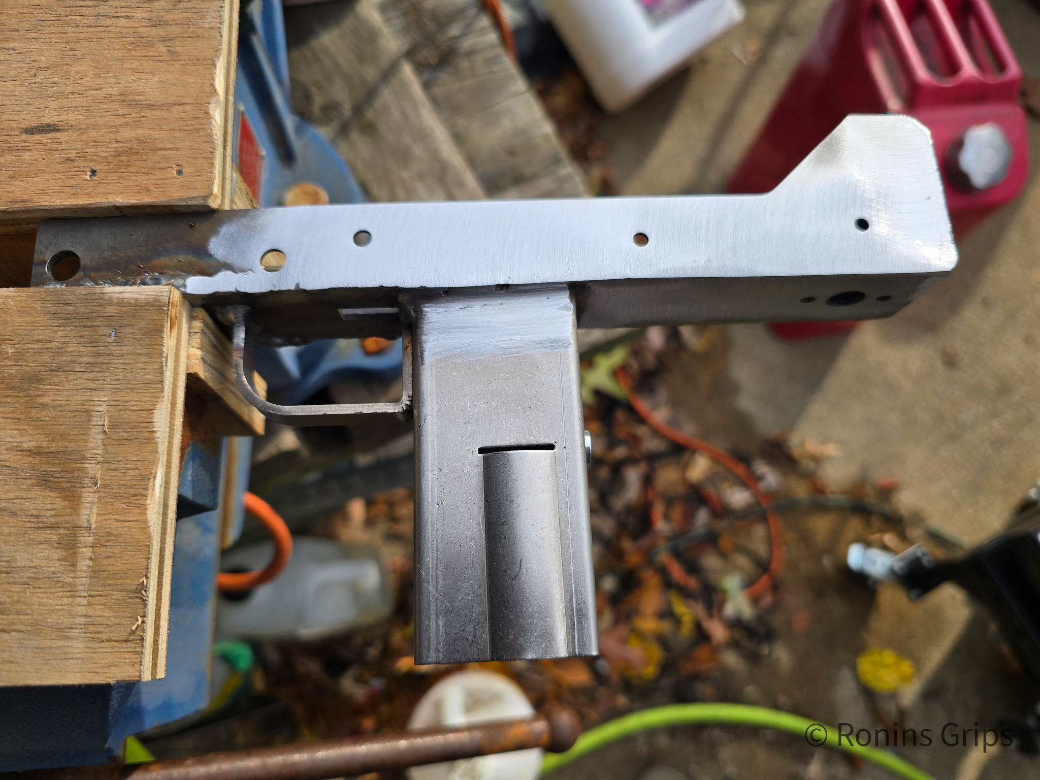
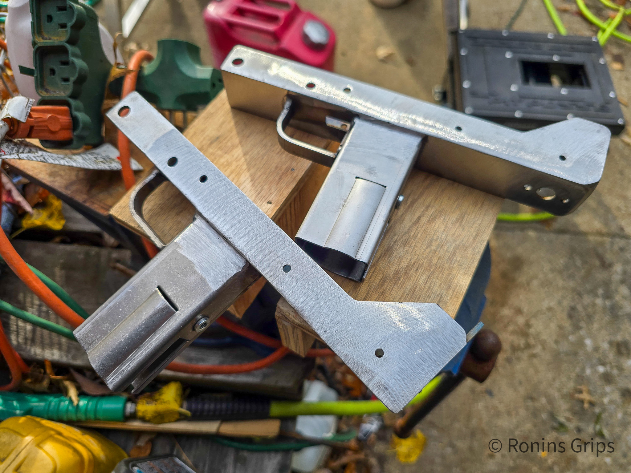
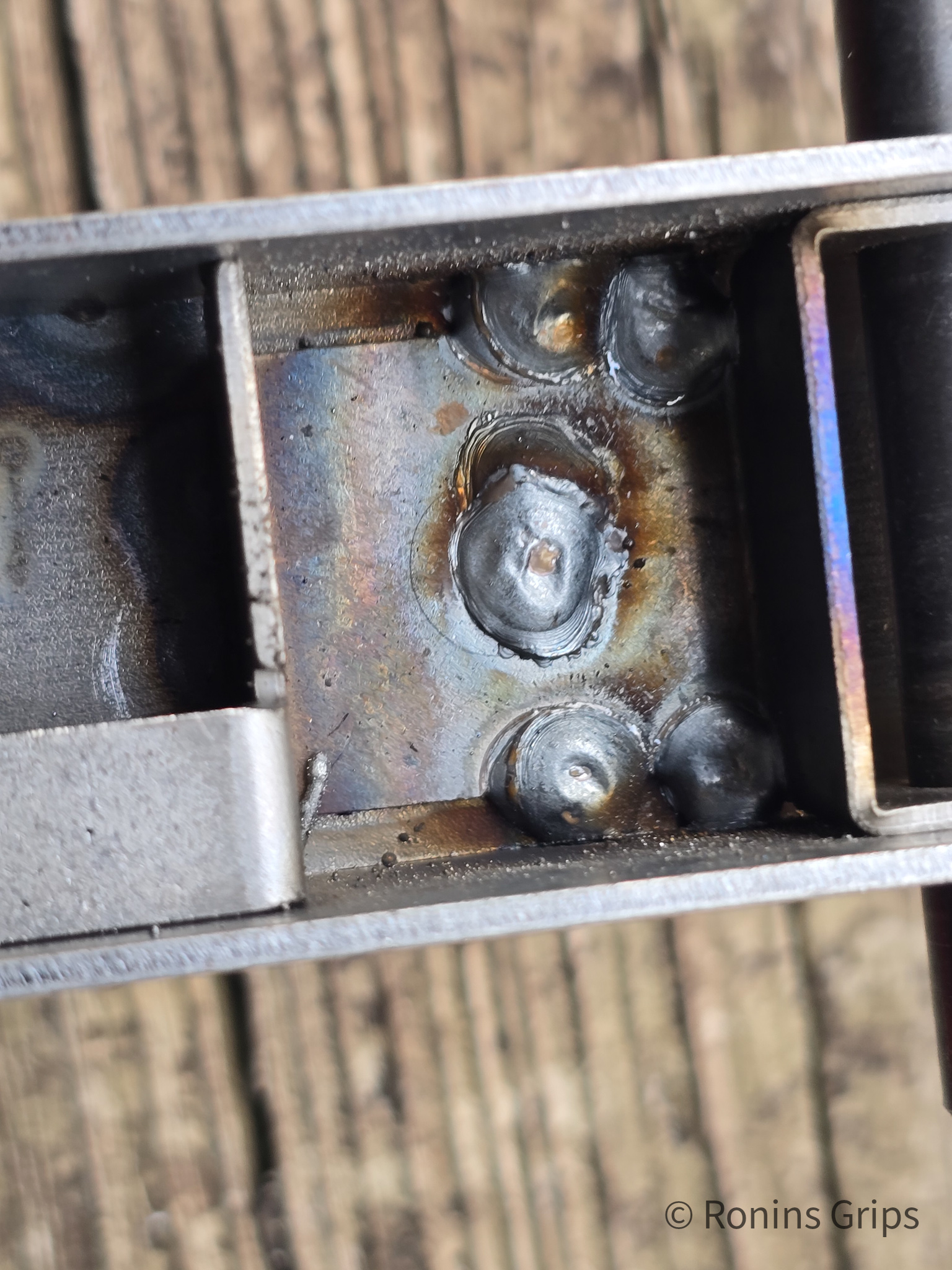
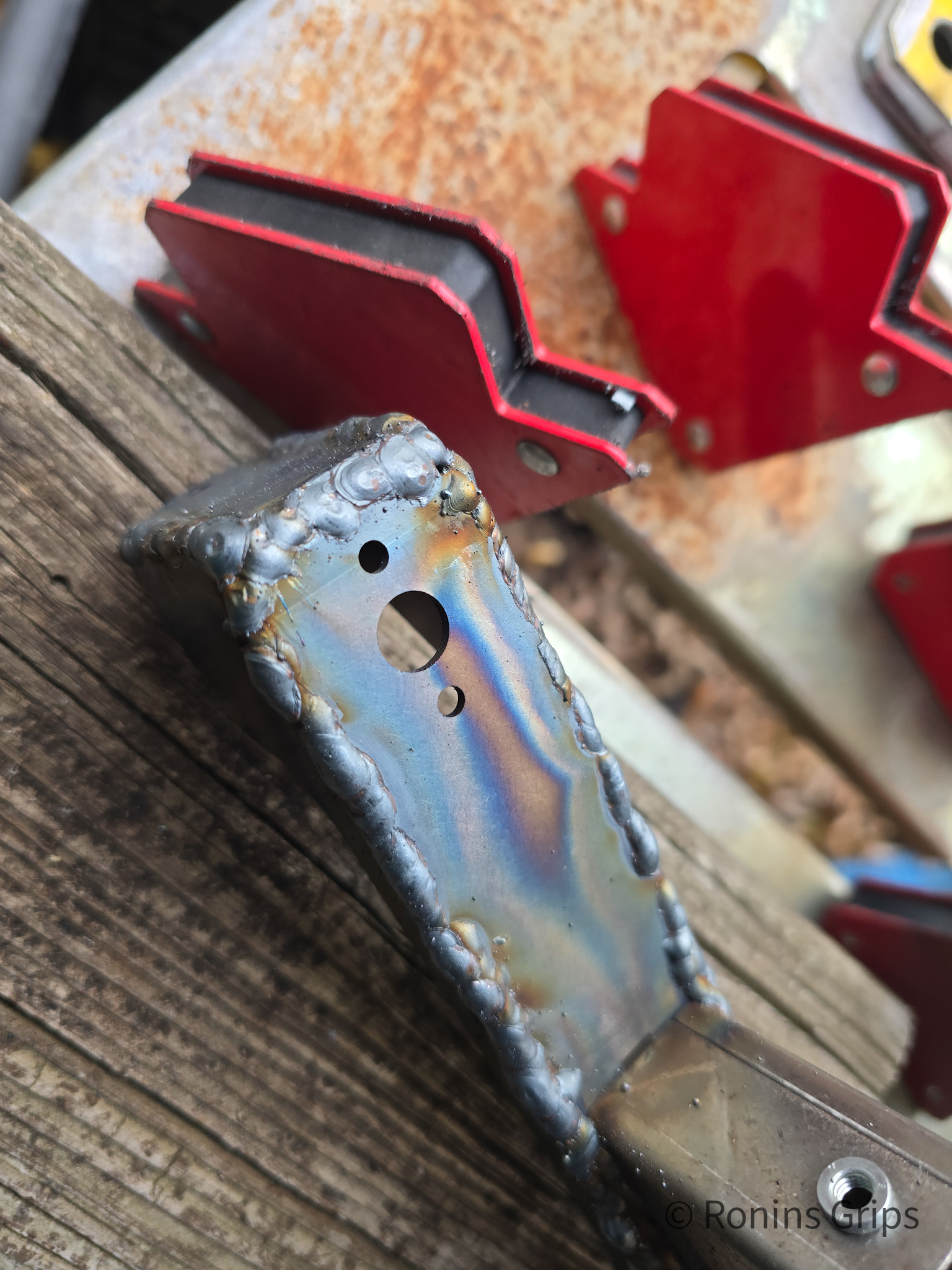
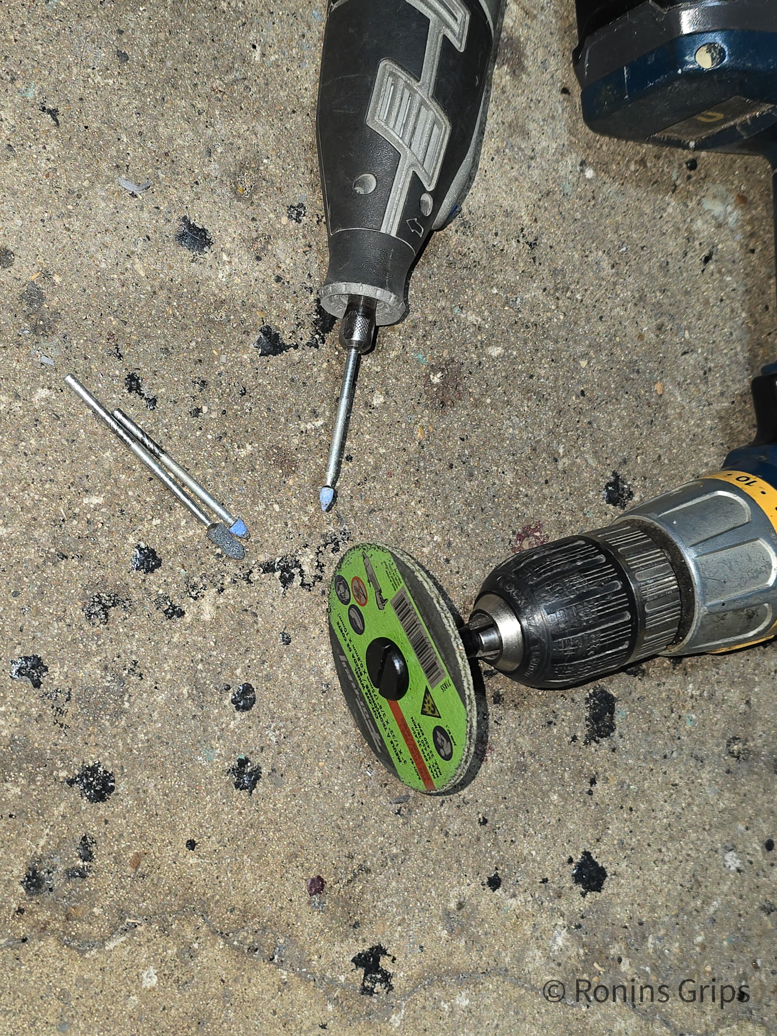
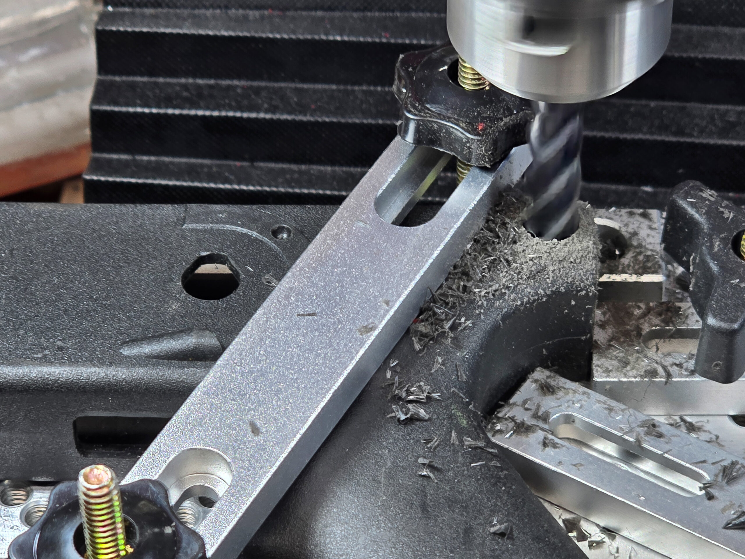
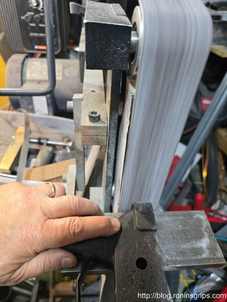
I tried to do the trigger guard, grip and center section all at once. A 6″ clamp and two pieces of 1/8″ thick scrap metal were used to evenly clamp the grip to the center support. A 2″ clamp was used to secure the trigger guard to the grip.When you weld sheet metal, do not just pour on the heat. If the sheet metal gets too hot it will sag/melt. It will also likely warp. To avoid this, tack weld the pieces together first. Tack welds are small spot welds. When everything is tacked, go back and weld small sections at a time rotating a round to keep the heat and warping low. I did not do the above all at once. Note you do not weld the back of t he grip or you will block the black plastic grip assembly.I inserted a piece of right angle aluminum in the front and clamped down the one side. You do not heed the right angle – the center reinforcement is plenty but I did not know this yet.I welded the slide plates on – first with tack welds and then increasing the welds. A 21/64ths” drill bit shank holding the center reinforcement in place prior to doing a spot weld in the visible hole. I did not weld the top rear of the receiver to allow for tuning. The red objects are magnetic clamps.I did a weld in the middle and then on the sides just to make sure things don’t move later.The welds look like crap you say? Yeah – but if I can pull this off so can you. I shoot single welds and aim for good penetration due to my tremor. Then I grind/sand to clean up.I use a Ryobi 18volt 4.5″ grinder with a 7/8″ arbor and use Neiko 40 grit flap sanding discs. I like the Neikos because they are thicker than cheaper models and the grit seems to last really well. I did not wear out one disc doing all three receivers.So the Neiko flap sander did the bulk of the crude work. I did use a 120 grit disc to quickly clean up the three receivers before I abrasive blasted and parkerized them.40 grit sand paper in a grinder can take off material fast – even steel. I’d recommend having the work at a comfortable height secured in a vise. The wood inserts you see are something I slapped together for my big 6″ outdoor vise to hold the receivers and not tear them up. The vise has hardened jaws and would chew up the mild steel receivers if they were holding them directly. At any rate, be conscious of the angle of your grinder and focus on knocking the beads down. Take care not to let the grinder remove/thin out the base sheet metal.Done for now. I later levelled most of it our using a 120 grit flap sanding disc before abrasive blasting. The whole point of this is to fusion weld the pieces together and remove the extra beads. I then used a sanding mop to round over the right angles on the sides. By the way, these are for my own use. I’m not selling them so they just have to be good enough to me.
Lessons learned: 1) Don’t need the aluminum right angle to orient the side plates. The rear bend in the center section and the takedown pin reinforcement can hold it just fine. This dawned on me as I was sliding the reinforcement section into position. 2) a piece of sheet metal on top of the side plates would probably be a better way to secure them. 3) Also, I really needed to connect the ground straight to the receiver to get a better connection.
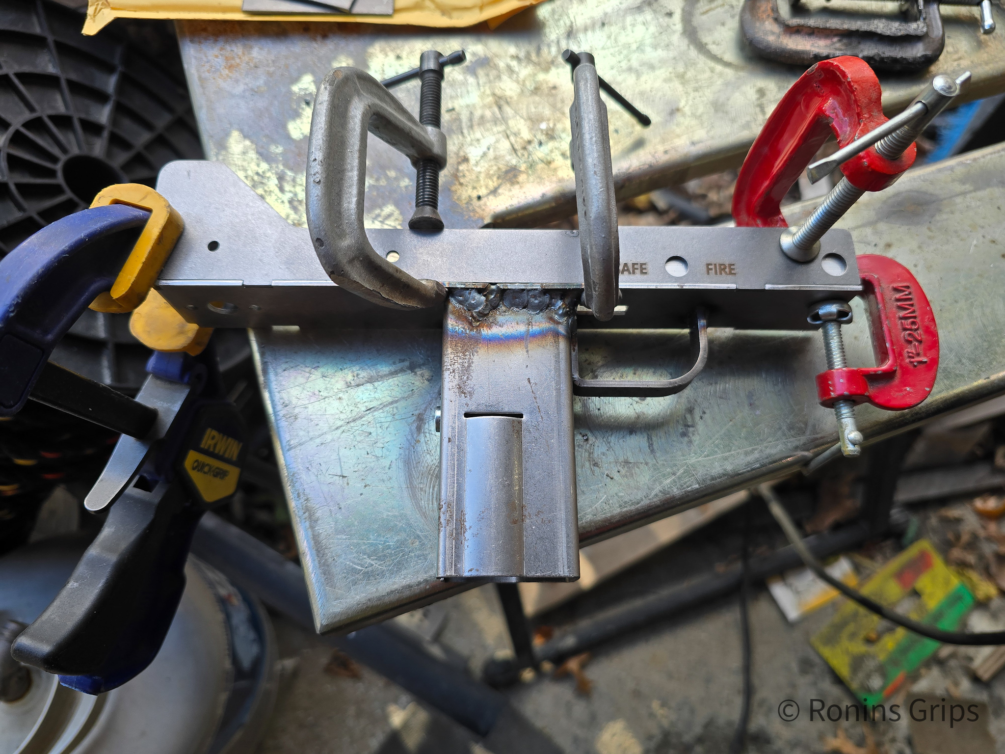
Second Receiver: I clamped the trigger guard, grip and center support together and welded them. Then I inserted the front reinforcement and clamped the side plates at the front, back, middle and welded. I then did the rear sight plate.
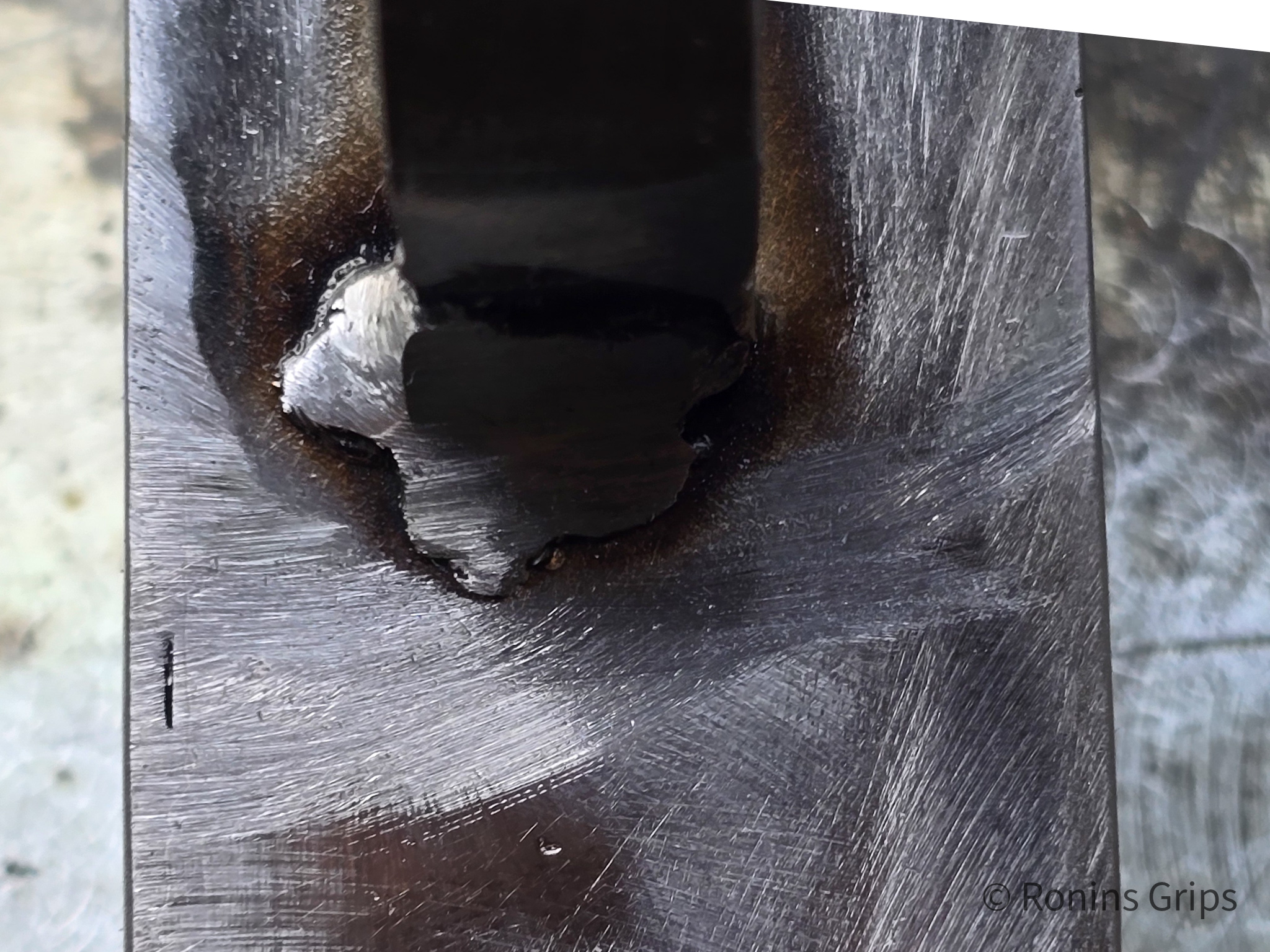
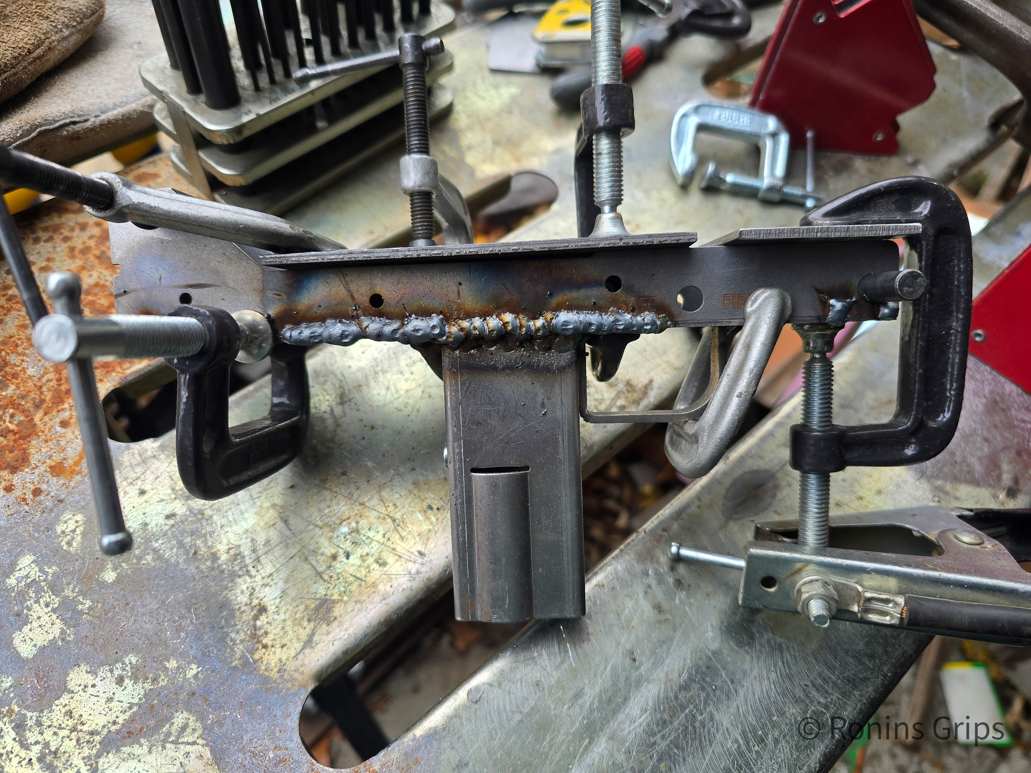
So the second one started in a very similar manner.But this time, I took more photos and with better lighting.Tack welds are in.I was clipping right along feeling good about stuff but broke a cardinal rule – I didn’t check the clamps and the workpieces. The magwell/grip is true but trigger guard assembly cocked sideways somehow and was no longer perpendicular with the center section. Well crap! So, I used a Dremel with a cutting wheel to cut off the trigger guard and welded it square. I used pliers to true the bullet guide so it was perpendicular the way it should be with the receiver. The slot you see is where one of the side plate tabs went into the recess on the center section. I welded them closed and ground them flat later.I used plenty of clamps to make sure nothing else moved and then did the spot welds. Note the ground is right on the receiver. The magnets are keeping the assembly from moving. You can see the spot welds. I would then move around welding a bit at a time to avoid warping or sagging. There is a 21/64ths transfer punch aligning the center takedown pin reinforcement.To be clear, I welded the center section after the side plates were welded in. The I pulled out the alignment pin – in this case a 21/64″ transfer punch.Clamped getting ready for the flap sander. Note, I would need to move the receiver around about 4 times to get all of the material off. It was never in one go.A good chunk of the weld bead on that side was gone at this point.Two roughed in receivers. No finish sanding yet.
Lessons learned: 1) Check your clamps and work to make sure nothing shifted. I could have kicked myself – that was such a basic mistake. 2) the center section may not be true – use some scraps of metal to pull the center section and side plates together. 3) More clamps are better than fewer clamps. 4) Maybe I should try welding the trigger guard by itself first – and I did that with the next one.
Third Receiver: Clamped the trigger guard to the center section and welded it. Positioned the magwell/grip, clamped and welded it. I then positioned the front reinforcement piece, clamped the side plates and welded.
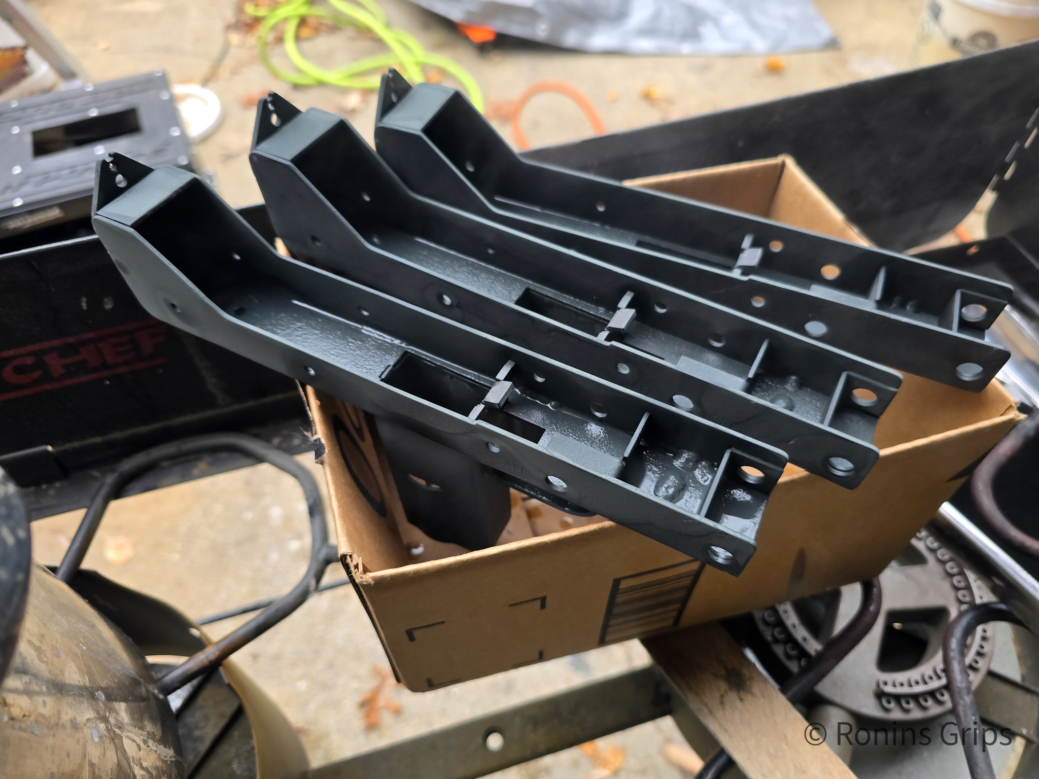
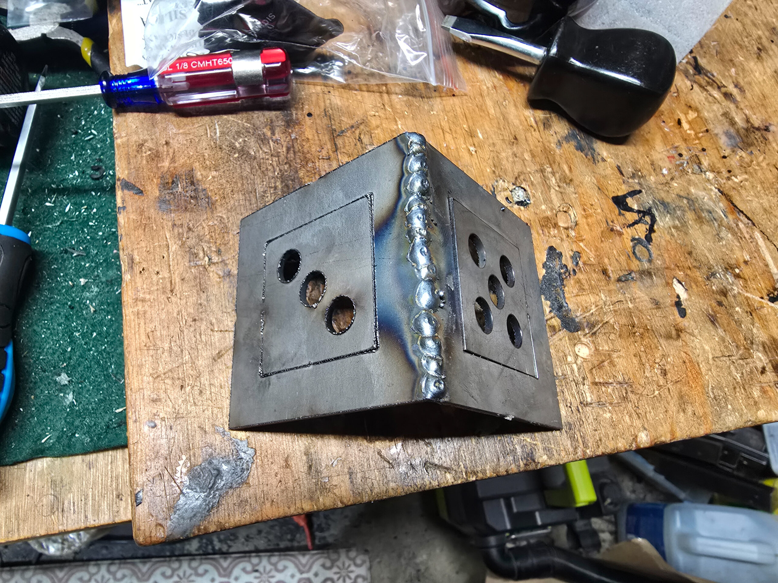
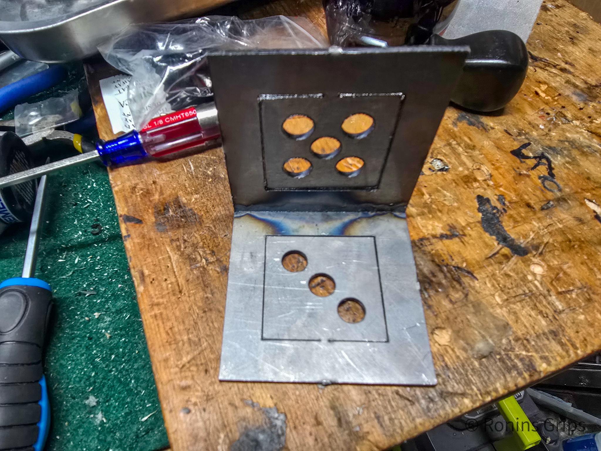
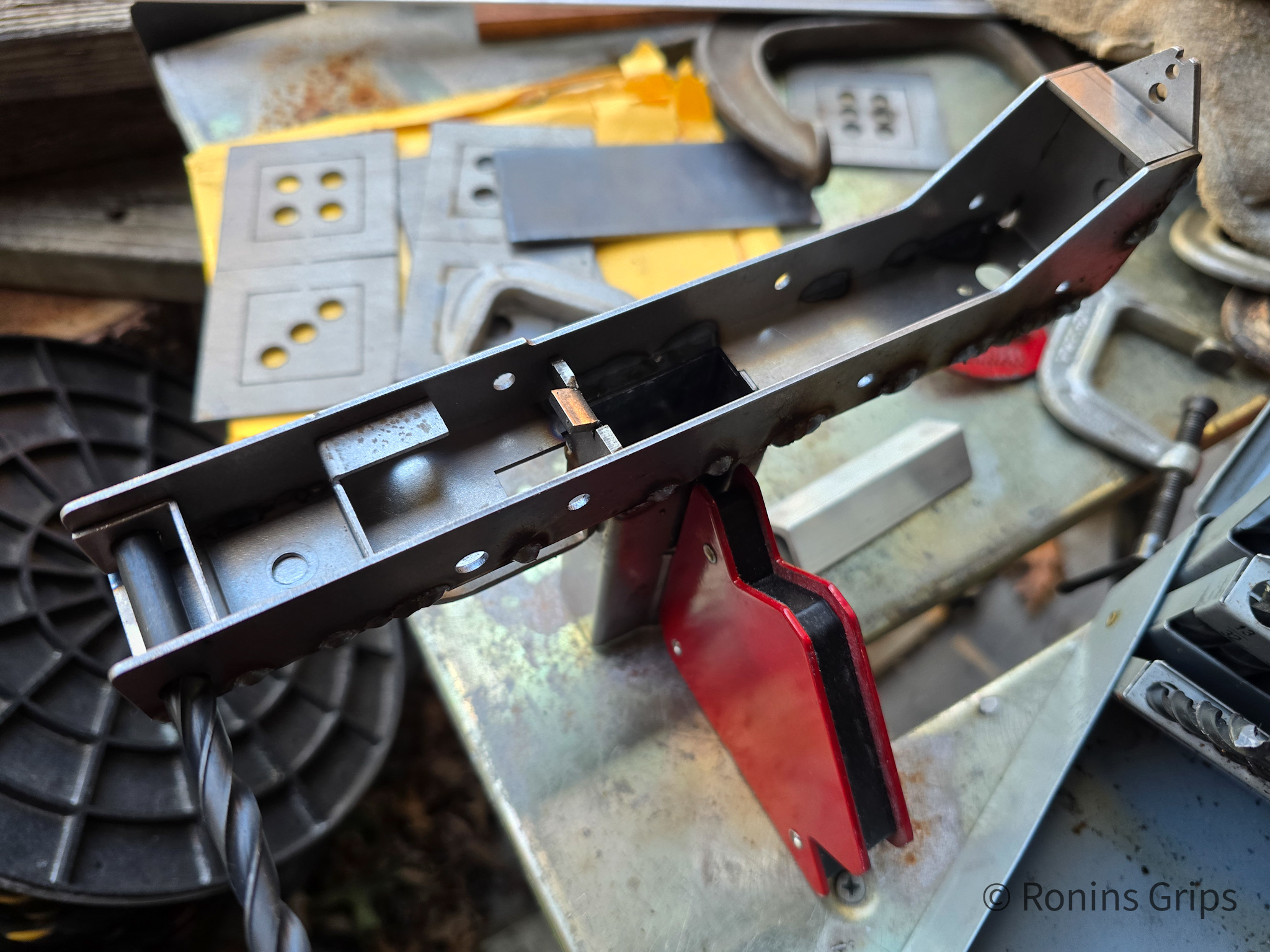
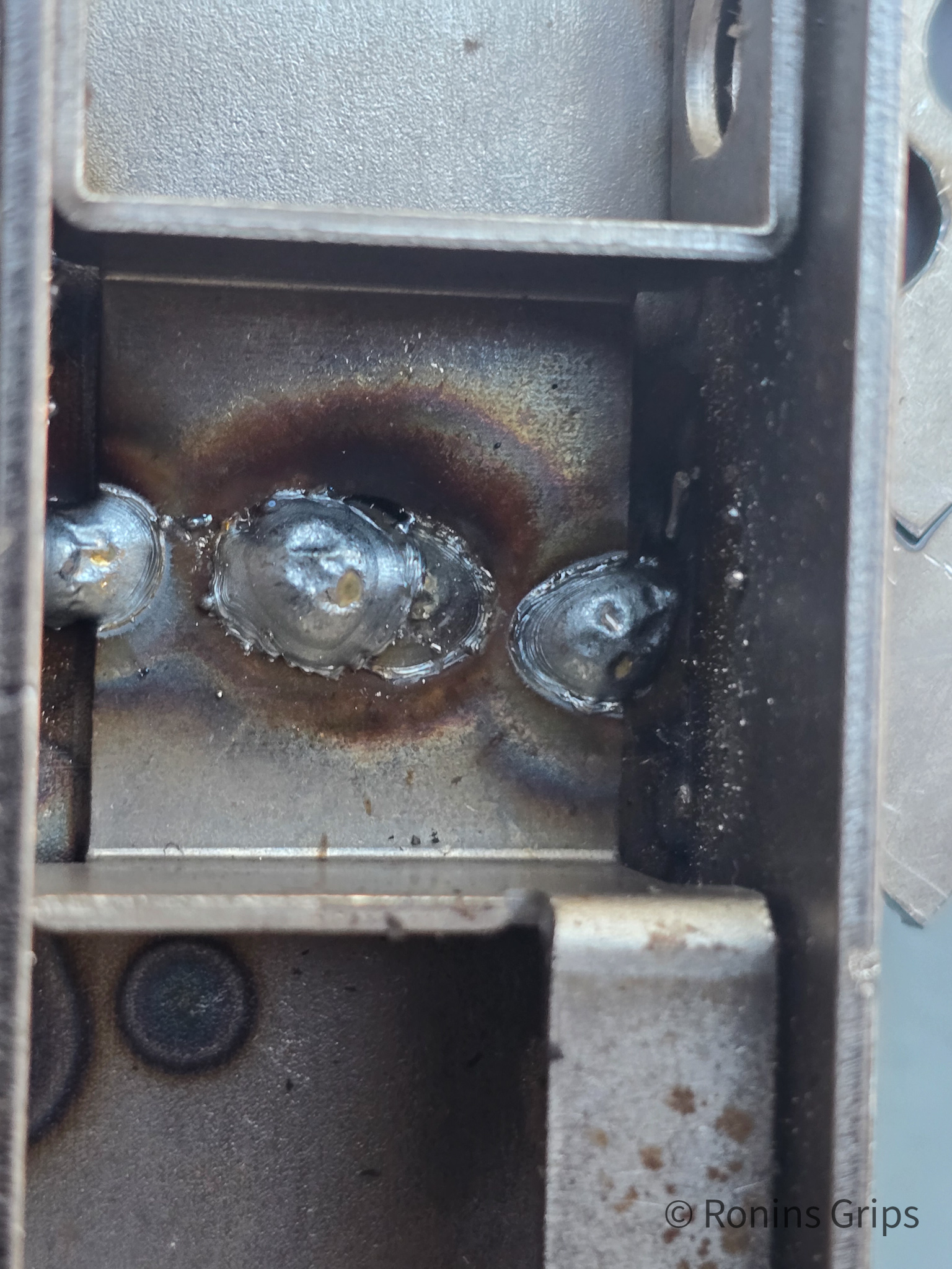
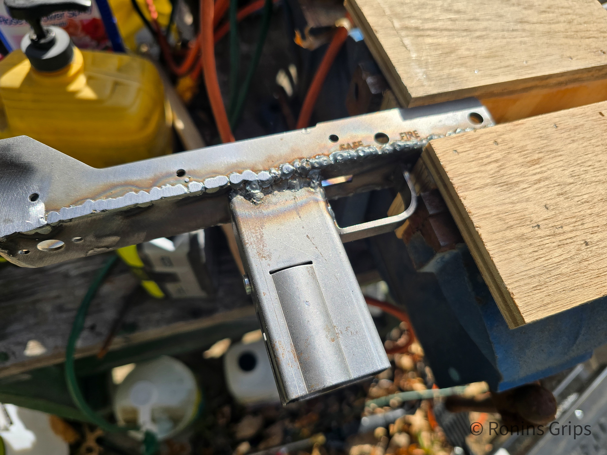
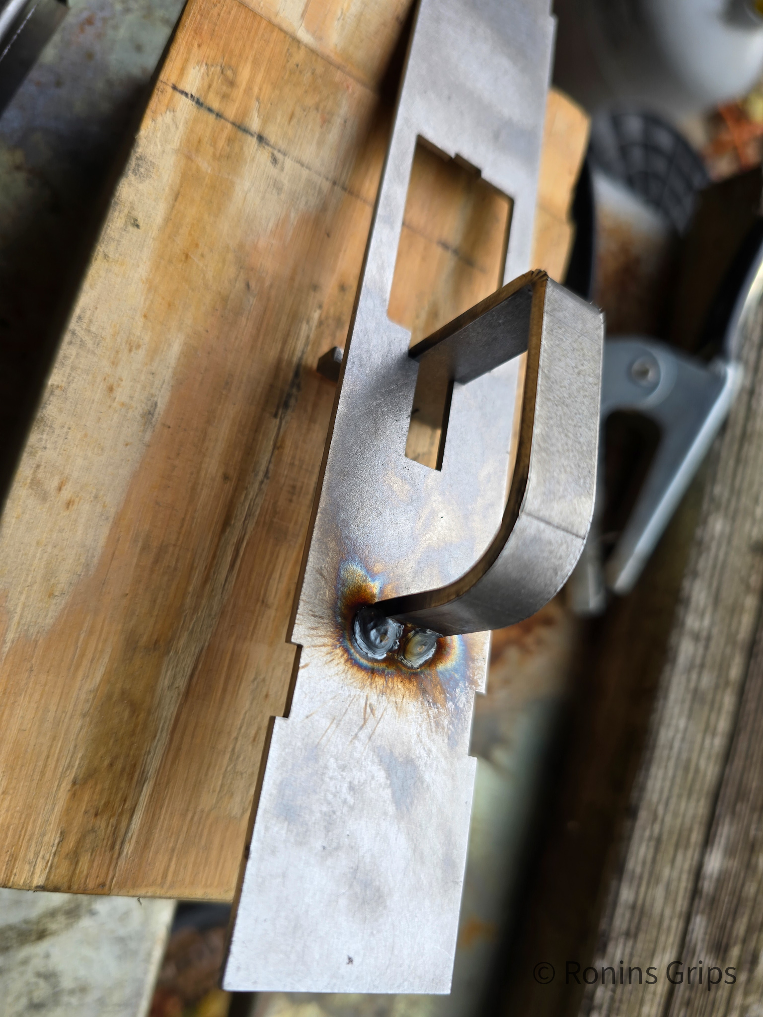
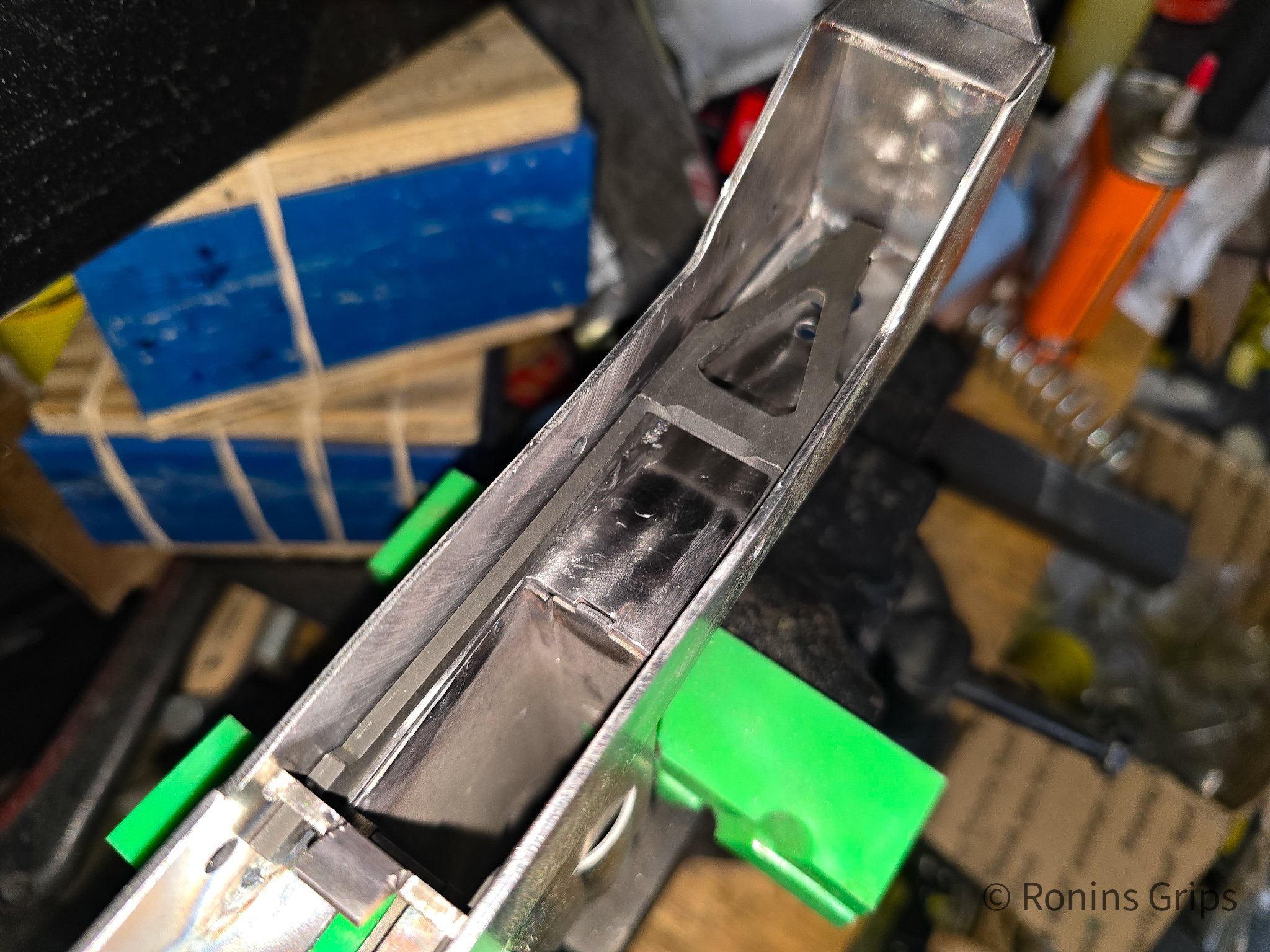
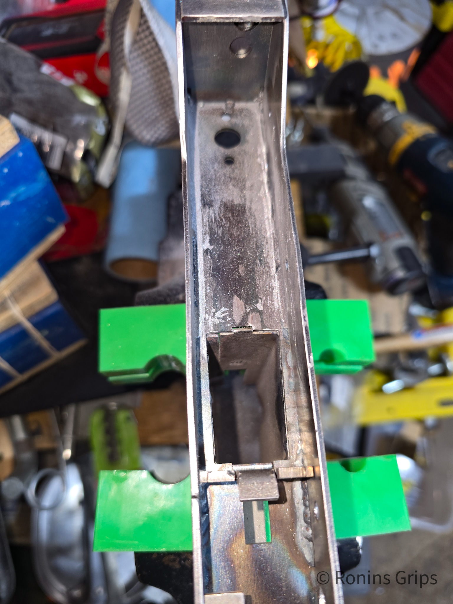
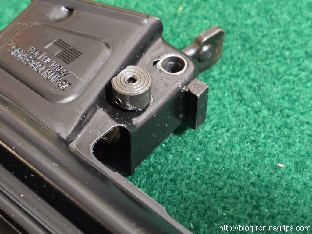
Through the use of magnetic clamps, I made sure the trigger guard was all of the way forward, true and tacked it in place. Then I moved on to the magwell/grip.So then I clamped the magwell in place, did the tack welds and then welded it all in.I’m holding it together but see how the plates are held vertically by the bullet guide and the front reinforcement? The trick is to properly locate everything and then clamp it.So I’m welding along the seam. What you can’t see is that I let it get too hot and I pushed through the other side in a few placesI welded in the ceterpiece. You can see the 21/64″ hole center punch aligning everything.Finishing up the weld on the seam.Welded in the rear sight plate. I welded the bottom edge closed so I could clean it up later – I did this on all three.I inspected the bottom of all three also. I added beads on all three receivers so I could get good penetration, fill in the slots where the tabs went and have a right angle I could then sand over. Again, note no weld on the rear of the mag well.Time to sand it down and clean it up.Again, we sand down all of the beads and clean things up.And number three was done awaiting finish sanding and parkerizing… or so I thought.,
Testing & cleaning up
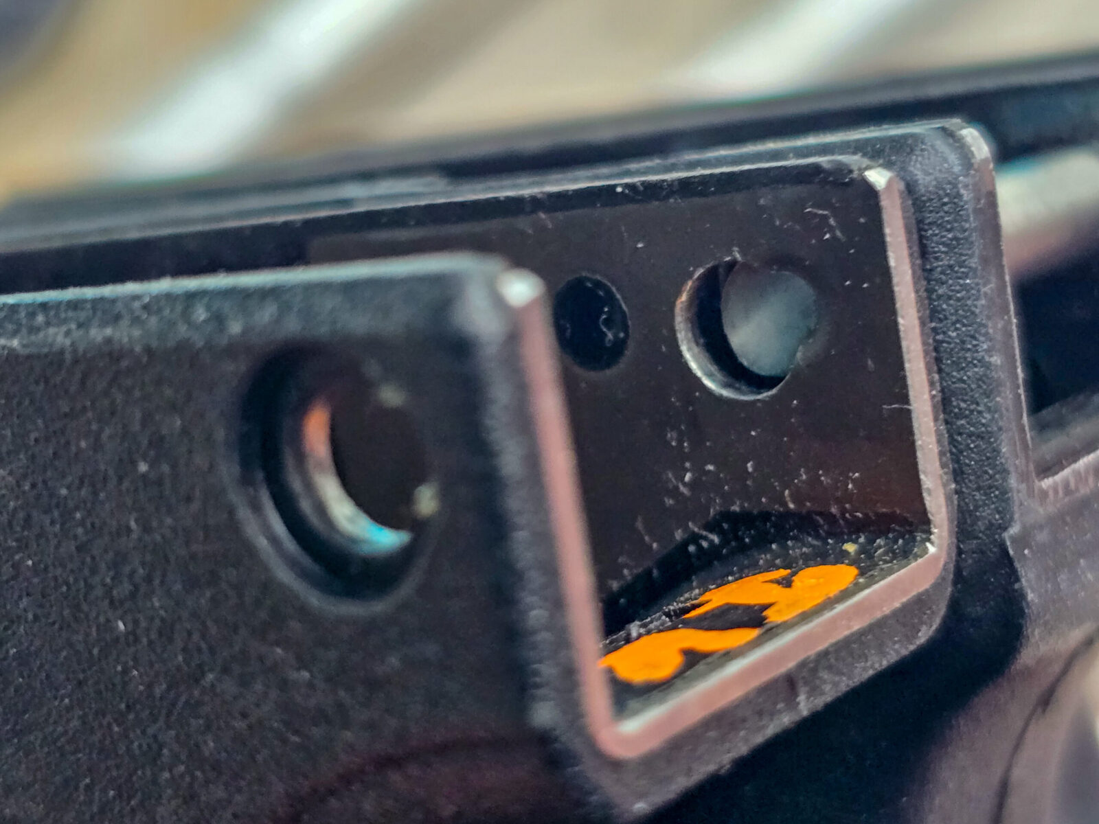
Okay, you need to make sure thee sear plate can slide from the back all the way to the forward towards the center support. The reason being is that if you have any welds interfering with it’s ability to slide forward or the trigger bar, your action is going to be messed up. If you have welds in the way, you are going to need to grind them down.
The sear plate must be able to smoothly slide forward and backward and not have any welds in the way.
This is one of those things where avoiding them up front my not going crazy with the heat would have been a good idea on my part. My first two were great. My third receiver had issues and I even know when I did it.
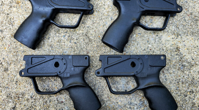
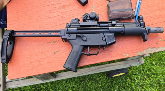
So far, things were going smooth. The VMAC9 lowers were welded together awaiting next steps. In the next post, I will cover how to given them a nice black manganese parkerized finish.
I hope this helps you out.
Note, I have to buy all of my parts – nothing here was paid for by sponsors, etc. I do make a small amount if you click on an ad and buy something but that is it. You’re getting my real opinion on stuff.
HK MP5K, SP5K – for the SP5K, slight trimming of the front locking plate on the grip will be required
POF 5PK
PTR 9KT
Zenith ZF5-P, ZF5-T, and ZF5-K
There are three required features for these to fit:
It must be an MP5K pattern weapon and not an MP5 or other variety of roller lock.
It must have an HK MP5K patterned top rear hole.
It must have a front shelf that the grip’s front locking plate rests on.
Technically, our Contract Contour and Navy SEF grips do support the front lower pin that some MP5Ks use. However, our converted Magpul SL grip does not have a front lower pin and does not need it because it is pushed forward against the weapon’s shelf and can’t slide out of position.
How They Are Made
Interestingly enough HK33, HK91/G3, HK93, HK94, MP5, and MP5K grips all have the same size polymer core grip albeit with different metal “tails” sticking out of the rear to accomodate whatever weapon they are meant for. Now there may be other models out there as well – but those are the ones that I know of so far.
This is a used HK G3/91 Navy SEF grip. The core black polymer shape is the same size as what we need for an MP5K.
The first step if you have one of these model grips is to removed the “tail” so the length will be correct for a MP5K, I would recommend cutting off the tail and then deburring it. Do not remove any polymer so you can get a firm fit when you install whatever stock, brace or end cap you plan to use.
This is a new HK 91/G3 Navy SEF grip with the tail cut off. I use a bandsaw to cut them with a fine tooth blade.
Measure the Existing Rear Hole Centers and Countersink Depths
To cut the rear holes is a bit more involved. First, you need to locate the centers of your existing MP5K grip’s rear holes. I’d recommend using quality calipers but you can do whatever you are comfortable with as long as the method is relatively accurate.
I would also recommend you measure from the front of the steel plate inside the front of the grip back to the center of the hole on your existing grip. That gives you the horizontal distance. To get the vertical distance, measure down from the top.
Measure from the front of this plate (the surface facing you in this photo) back to the center of the hole.
You should measure this on both sides of the grip. You may find they are not exactly the same. Regardless, double and triple check the horizontal and vertical measures on both sides.
The other measurement you need to find out is how deep to drill the countersink hole – the recession in the grip where the head sits on the left side (looking down) and the end with the wire retainer protrudes on the right. You may well find that the two measures are different again.
What you need to ensure is that the rear takedown pin’s working distance can span from the left side to the right side. The working distance of a takedown pin is the measured length from just under the head to just before the retaining wire comes out of it. The pin that sticks out of the other end of your calpers is for measuring depth. There are also far more accurate tools purpose-built for measuring depth also.
When you do you plan your countersinks, you need the distance the pin spans to look something like this:
Minimum depth of countersink = outside grip dimension – takedown pin working length
Now how you make that happen is up to you. For example, if you need to remove 3mm and want to split it to 1.5-1.6mm per side – that’s fine. Ideally, you want the pin to stick out far enough on the right side so the wire retainer can pop up and help hold the pin in place.
Milling the Countersink & Pin Holes
These operations require end mills that can make plunge cuts – meaning the end mil has cutting surfaces at the bottom and not just the sides. These are sometimes called “center cutting” end mills also. I would also recommend four flutes for a smooth finish.
The actual countersink diameter is 9.5mm but if you don’t have access to that, a 10mm end mill will work also. The takedown pin hole is 6mm. How much you want to spend on the quality of the mills is up to you. The polymer will not wear the 9.5-10mm bit much but the 6mm bit will need to keep its edge long enought to cut through the steel reinforcement on both sides. I’d recommend the6mm be either cobalt or carbide and not just high speed steel – or at least not cheap high speed steel.
Milling the 10mm countersink. My mill has a Digital Read Out (DRO) so I know how deep to go.
If you are wondering why not use a 6mm drill bit, it is because you will likely encounter a hole in the reinforcing plate that was cast into the grip during injection molding. A drill bit will hit that hole and want to yank the workpiece upwards as the edge of the opened hole rides up the flute and makes a mess. An end mill doing a plunge cut will not have this problem as it will cut off the open circle’s ends.
That slightly offset circle is exposed when you do the countersink. A drill bit will cut open the circle and then the grip will want to ridge the bit up.
So, yes, you can use a drill press but what is incredibly important is that you have the workpiece held firmly so you need to clamp it down.
Make a wood or plastic insert that you can put in the top of the grip to keep it from deforming when clamped and then milledd/drilled. If the grip moves at all, your new grip will be ruined.
Honestly, 99% of my challenge was figuring out how to securely hold the grips so they wouldn’t move and also not introduce angles/canting, etc. I’m still working on improving this as the overwhelming amount of my defects are caused by unintended workpiece movement.
You need to locate your new hole centers and then set up your milling machine or drill press to do the cuts. You need to figure out what works best for you. If you have digital read outs (DROs) then you probably didn’t need to read this blog post. If you are new to this, locate the hole center and mark the hole with a very fine point then use either a small drill bit or hole finder to center your machine on the hole.
To get the depth you need on the countersink, either use the features of your machine if it has some form of depth indicator or wrap a piece of tape at whatever limit you need and stop when you reach it.
I would highly recommend you do the countersink cut and then the hole cut on each side before you move on to the next. In other words, do a side at a time before you move the workpiece.
If you are wondering why I am not mentioning how to locate and cut the front pin holes, it’s because you don’t really need them if your weapon uses a shelf, which most current HK grips do. For example, the Magpul SL grip does not have the front holes. The way the polymer is formed, you would likely need a longer pin and it’s not going to give you a better connection. The front plate of the grip is shoved against the shelf by whatever you have on the end of the weapon and the top rear pin keeps the grip from swinging down – that’s really all that you need.
Here is a batch of converted “good condition” real HK Navy SEF grips getting ready to go to their new owners. We do repair any minor gouges and apply a restorative finish to make them look good. That’s the original HK paint by the way. Click here if you are interested.
Summary
You can do the conversion or buy our ready to go grips. You may need to do some final fitting but we’ve done the hard parts. If you’re interested, click here to go to our HK Grips page.
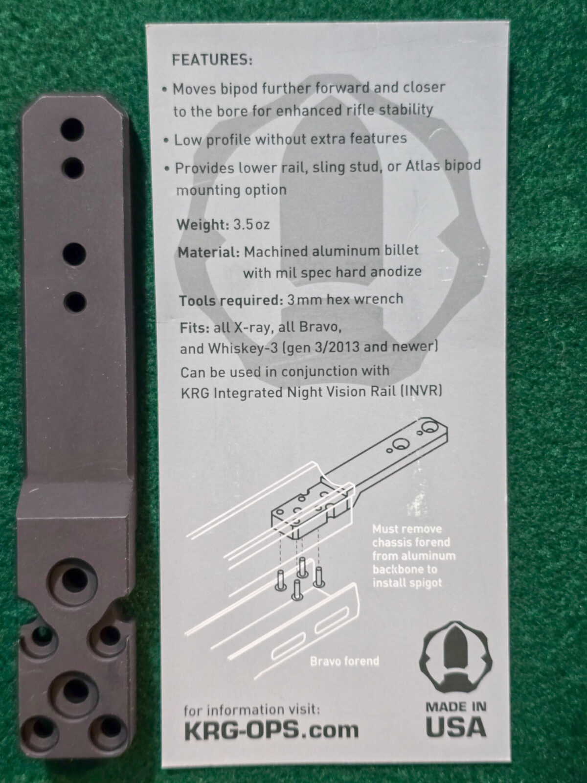
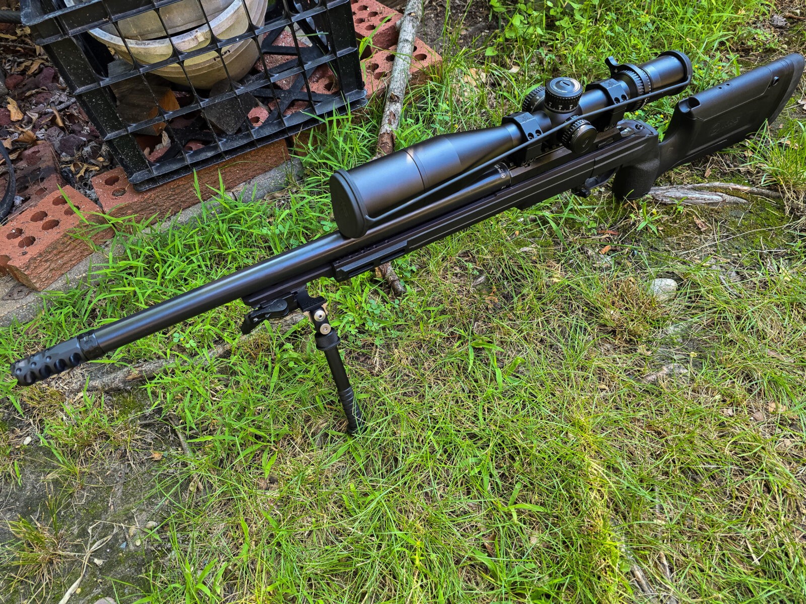
In my last post, I mentioned my disappointment that the Kinetic Research Group (KRG) Bravo chassis that Aero Precision sells with some of their Solus bolt rifle offerings is not truly bipod ready. In my opinion, Aero should either have discosed that the stock isn’t bipod ready and/or given an option during the purchase of the Solus to buy one of the models of spigots that KRG offers. Okay, that’s water under the bridge. I want to make this post about adding a spigot to a Bravo.
It’s time for me to explain what I am talking about – a spigot is an attachment point that extends forward past the front end of the stock where a bipod, and sometimes other accessories, can be attached.
In the case of the Bravo, a spigot will connect to the aluminum chassis and both move the bipod mounting point forward and provide an extremely secure mount directly to the chassis.
Nostalgia Time
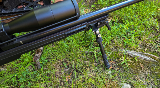
The first time I encountered a spigot was with Versa-Pod bipods. It’s been so long, I can’t recall if I found out about Versa-Pods and then bought an Accuracy International Chassis System (AICS) for my Remington 700 XCR LR or it was the other way arround.
You can see the spigot sticking out of the front of the AICS – in this case it is an adapter to use a Versa-pod bipod.
I don’t really recall when but at some point I moved away from the Versa-Pods mainly because I didn’t like the rotation around the spigot unless you really cranked down the locking knob. These days, my go-to bipods are Atlas models.
Back to KRG Spigots
KRG literally has a whole page of different spigots. There really are three factors that distinguish them – whether it is an ARCA pattern, how far forward you want the mounting point and what all you want to attach.
I’ll be honest – I actually had to call KRG to figure out what I needed. The customer service person I talked to was great and patiently explained the pros and cons of each based on what I needed:
I did not need to connect an ARCA device, such as a tripod. Since I did not need ARCA this also ruled out their really long spigot.
I only needed a bipod mount. Their normal spigot provides all kinds of attachments for rails, QD studs, night vision, etc.
Ok, no ARCA and just a bipod. That pointed me to the Minimalist spigot. The Minimalist moves the mount closer to the bore – which means you can get lower all things being equal. It also moves the attachment about five inches forward.
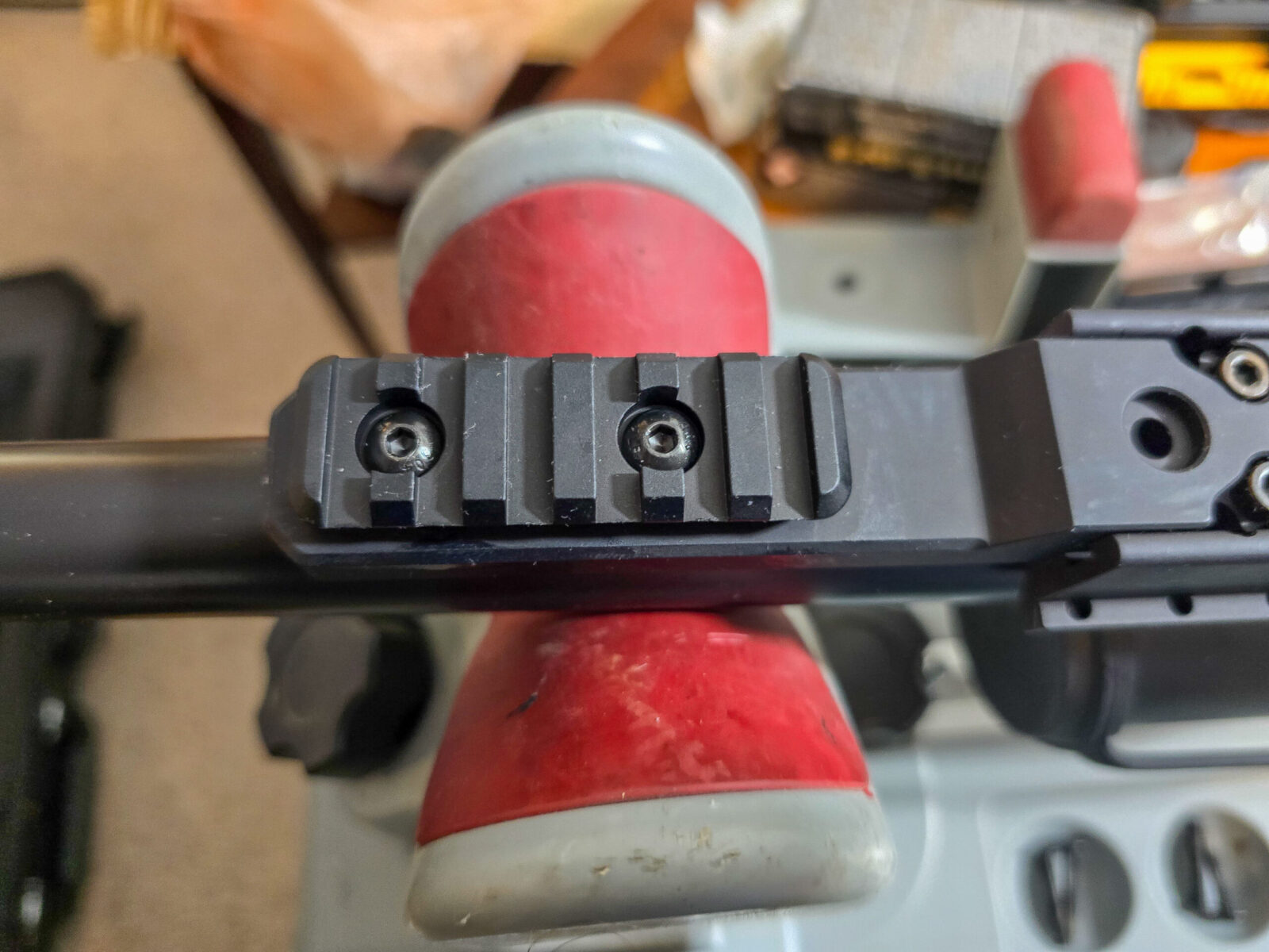
One thing with the Minimalist – it does not come with a rail section. You can either use the polymer one that came with your stock or buy an aluminum section from them. There rails sit flat as they not have the typical M-Lok boss on the back. This also means you can’t use a common M-Lok rail.
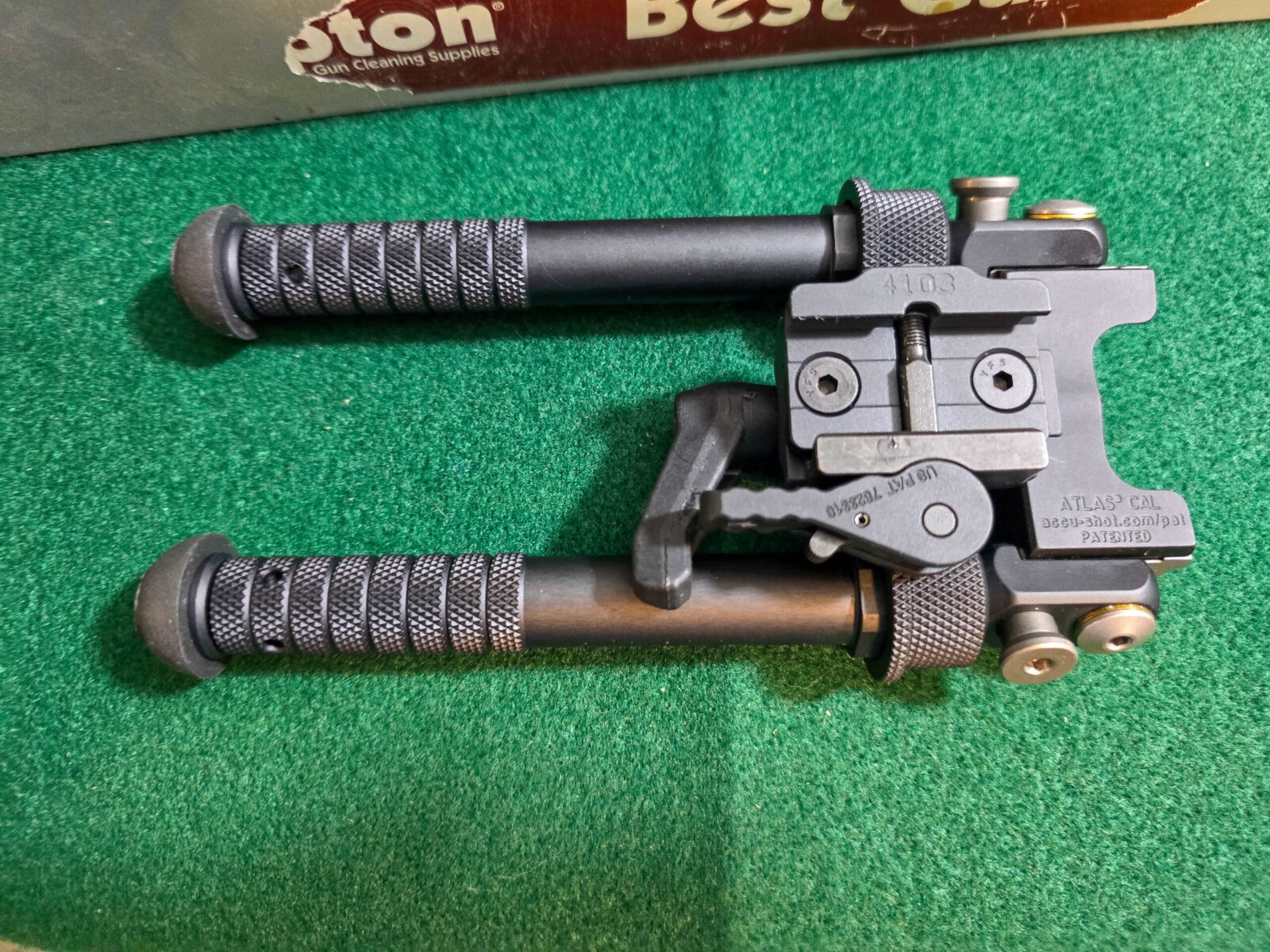
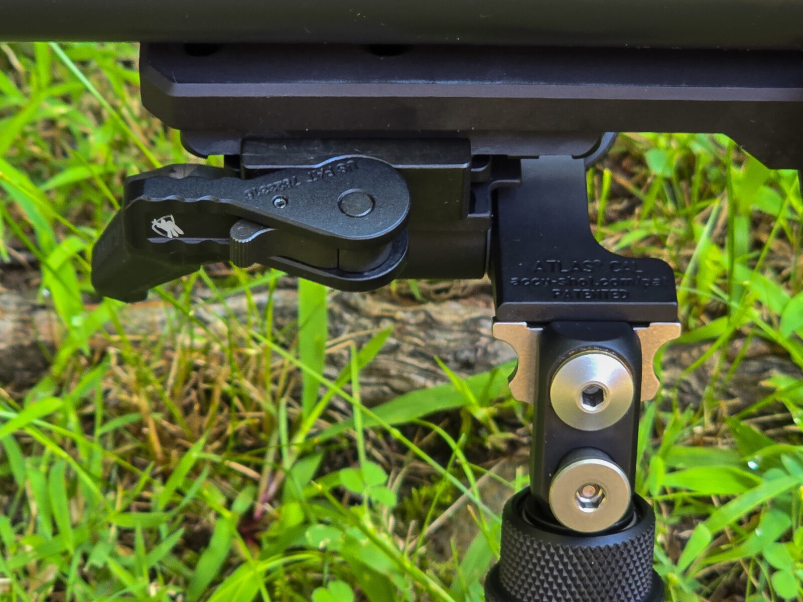
Your other option is to bolt an Atlas bipod or a Harris bipod they sell directly to the spigot. I like using a rail because I can pair it with an American Defense Manufacturing (ADM) quick release lever and have the ability to quickly take the bipod off if I don’t need it. For example, if I am shooting from a bench rest.
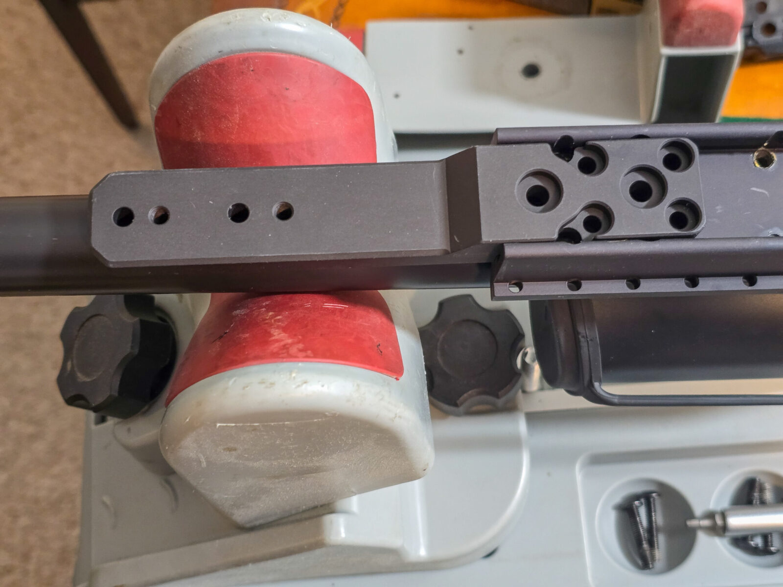
How to install the Minimalist spigot
If you can turn a screwdriver, you can install the spigot has there are just a few steps:
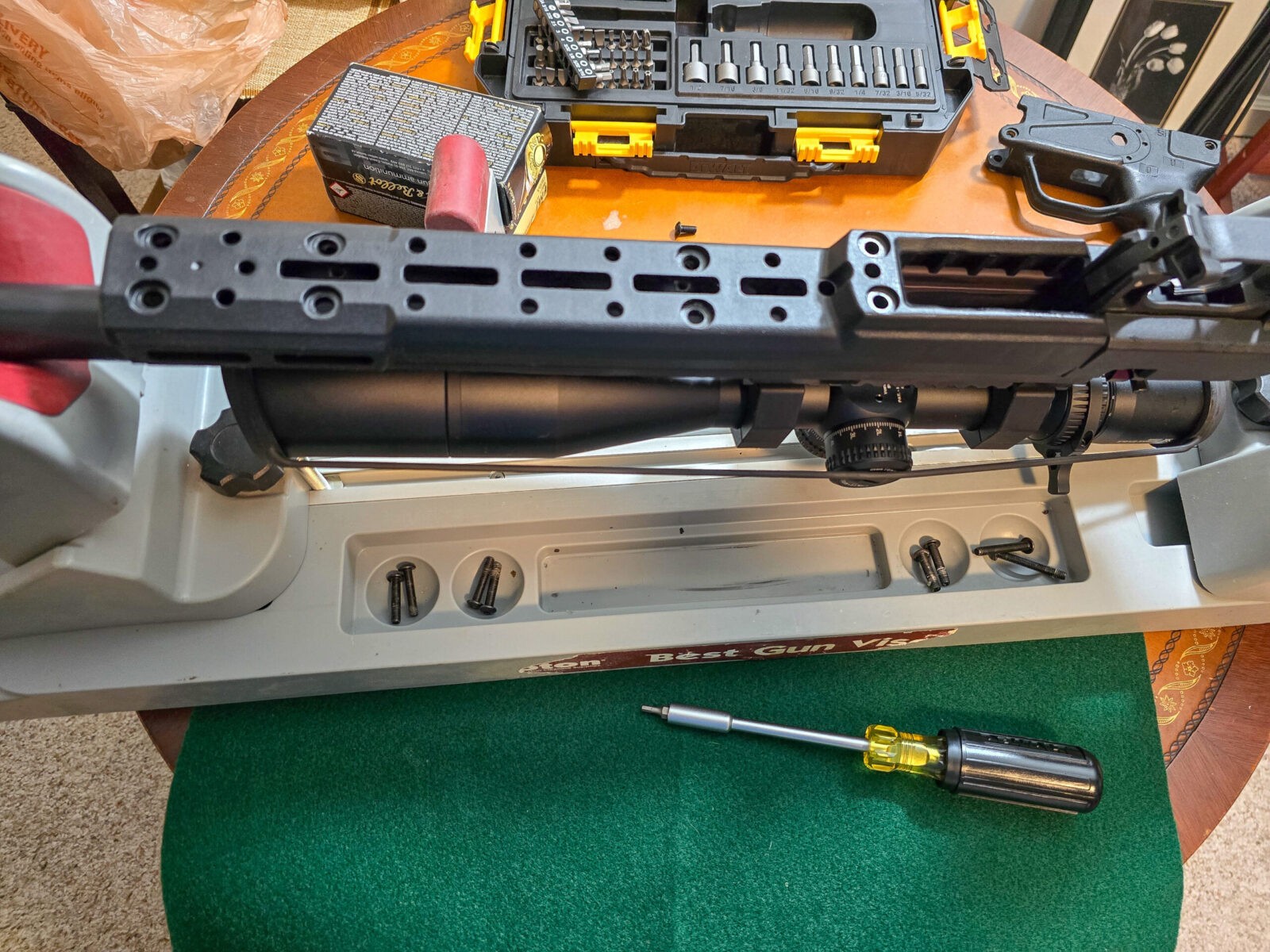
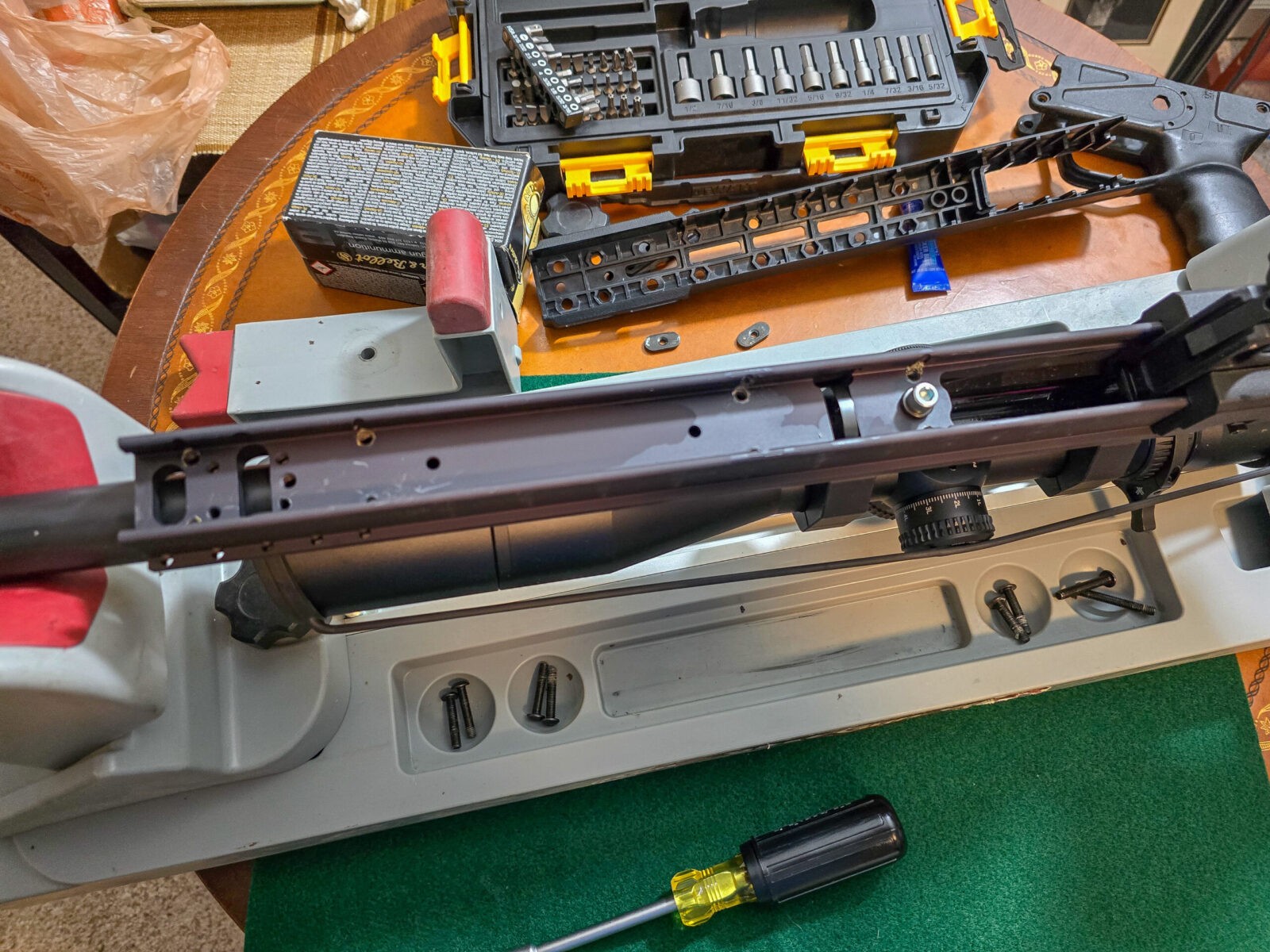
Remove the bottom chassis cover by removing eight bolts
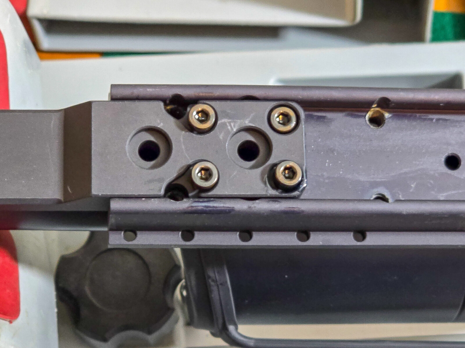
Screw the spigot into place – use blue/medium thread locker on the bolts
Apple blue/medium strength threadlocker to each bolt and screw the rail segment onto the spigot – assuming you go that route
Apply blue/medium strenth thread locker to each bolt and screw the bottom cover back on
It’s nice when something literally is that easy.
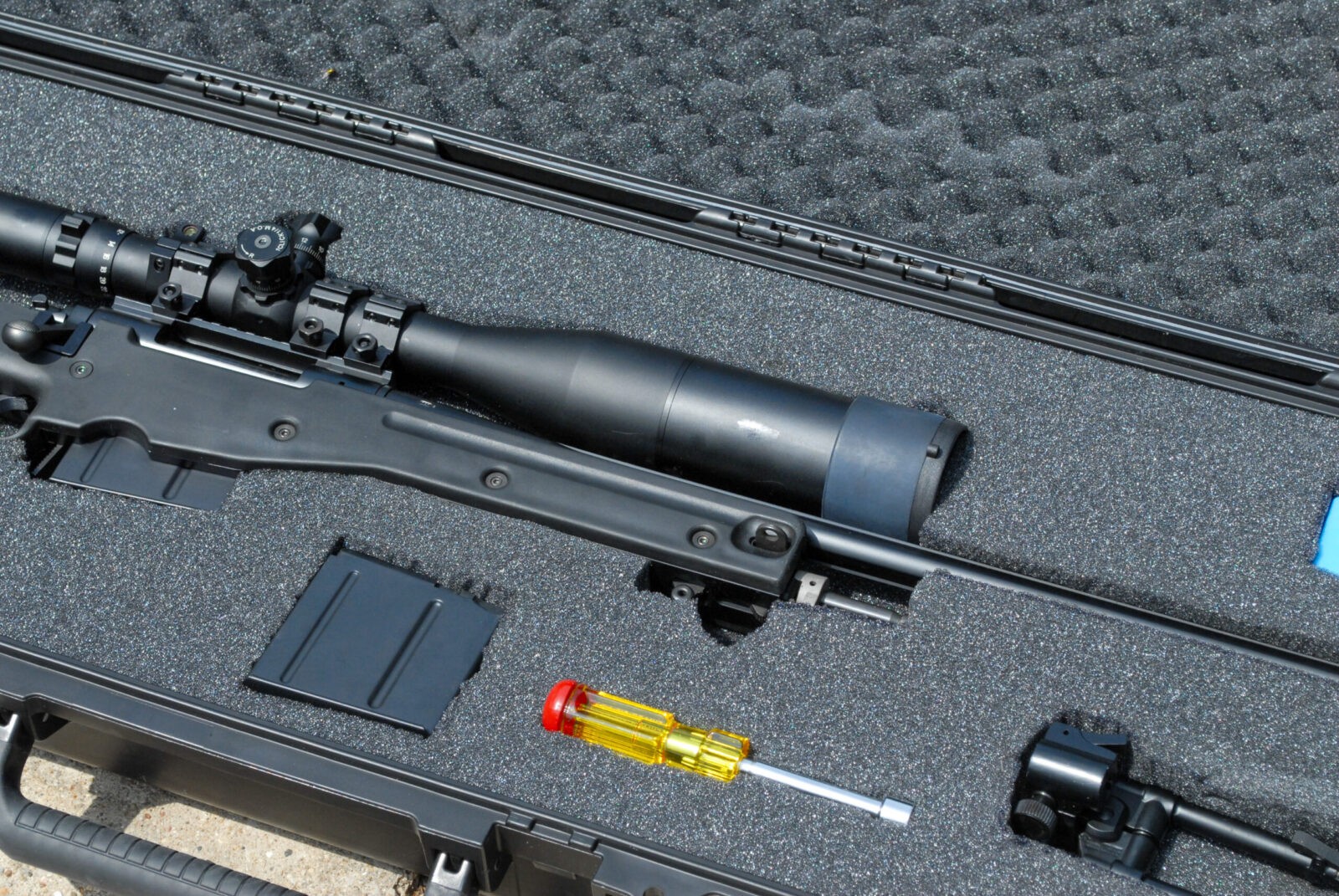
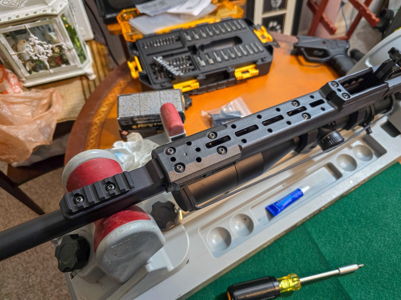
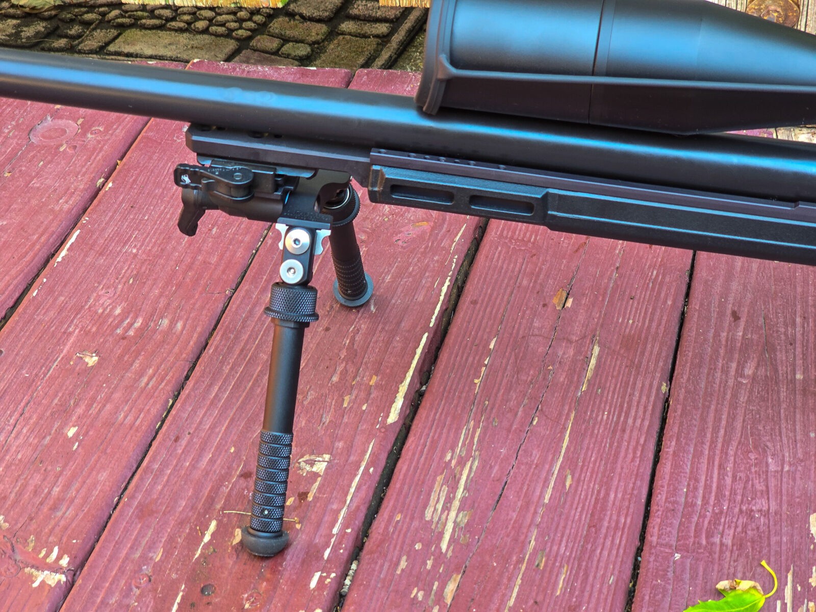
Remove the 8 screws that hold the cover on the chassis’ backbone. Note, the rear two are longer than the others.The spigot will screw on in the front.This is the Minimalist spigot that bolts right into place.The machining is very well done. The holes all line up and it’s just a matter of screwing it together.Apply medium strength thread locker to the screws they provide. Note the holes used above. The forward outermost holes in this photo are used to secure the cover.In my case, I screwed in the rail section after applying medium strength thread locker to the screws.Apply blue/medium strength threadlocker to the screws and install them. This is a polymer cover you are installing and do not need a lot of torque.. Bring it down snug/firm and let the threadlocker do its job.This is an Atlas BT65-LS17 bipod. The BT65s are great rigid bipods that don’t pan left and right. It uses an ADM LS17 quick release clamp to secure quickly to rails. If I had wanted it, I could have ordered the BT65 without the clamp and installed it directly to the spigot. Due to all of the counterfiet Atlas bipods that are out there, I buy mine directly from AccuShot. I’d recommend you do that or buy them from a reputable dealer. Avoid buying an Atlas model from eBay like the plague.The result is incredibly solid. If I had known how nice this setup was, I would have paid for it from the start.The ADM LS-17 quick release clamp does a great job holding the Atlas BT65 solidly in place.Here’s a view of the whole Solus Bravo .308 with the spigot and Atlas BT65-LS17 bipod.
Summary
Okay, I was starting to like the Bravo chasis more and more. The Minimalist spigot is absolutely worth it. You can then either mount your bipod directly or via a Picatinny rail section like I did.
Dear Aero – hint, hint – I would have paid for the spigot in a heartbeat had I known how solid it is and what a stable platform it can enable.
To anyone reading this who has a Bravo chasis – adding a spigot is very much worth it. I’m honestly glad I did.
I hope this helps you out.
Note, I have to buy all of my parts – nothing here was paid for by sponsors, etc. I do make a small amount if you click on an ad and buy something but that is it. You’re getting my real opinion on stuff.
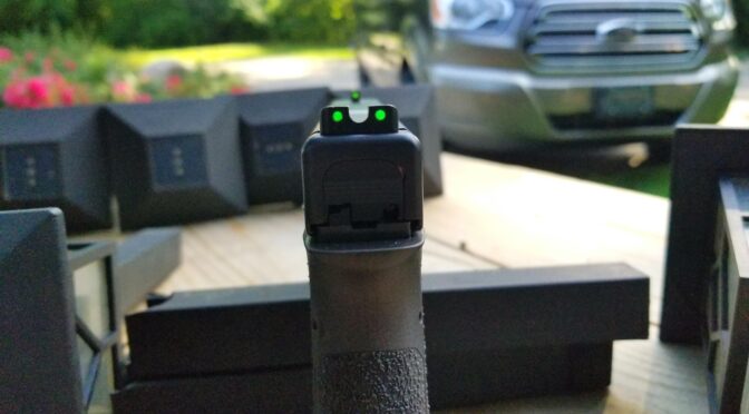
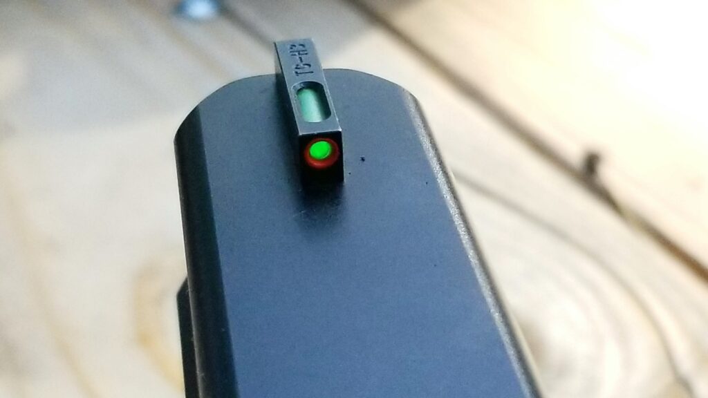
A fellow emailed me wanting to upgrade his from the generic OEM Glock sights that I don’t think really excite anyone to something that would be more visible in general and also work in the dark. My answer was immediate – go with the TRUGLO TFX Pro Tritium and Fiber Optic Xtreme sights.
The featured photo above shows how bright they are on my G17 slide on it. I bought these sights by the way – so you are getting my honest opinion.
Folks, these are my hands down favorite sights for a number of reasons:
They are CNC machined from steel and have a durable black nitride finish — they are not soft plastic.
They do not need batteries – the lit dots are via fiber optics when there is light and sealed tritium when it is dark so you are covered regardless of the light available. The tritium ought to fluoresce (emit light) for about 10-20 years and I’ll worry about replacing them then.
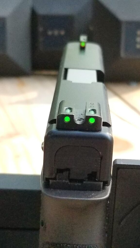
I really like the three green dot configuration – two on the rear sight and one on the front. The front also has an orange ring that you can see when there is light but is green when operating off the tritium only.
The rear sight goes into the slide’s groove very easily and is then secured with a set screw. Some sights can be a bear to install but not these.
The rear sight is big enough that it can help you rack the slide one handed in a one-handed emergency.
They have a 12 year warranty.
They are assembled in the USA – the tritium capsules are made in Switzerland.
What Glock models are supported?
Because these are so popular TRUGLO is making a variety of models to support the different Glock configurations that are out there. I assembled the following table and you can also check their webpage if you want:
This gives you a better view of the sights overall. This is the TFX Pro TG13GL1PC with the fixed rear sight. I really like the sight picture these give day or night.
Here’s the rear sight and you can just barely see the set screw that secures the sight between the two “ears”. The slot at the top of each fiber optic is where it collects light to illuminate the dot. If there isn’t any light then that is where the tritium capsules take over.
Here’s the front sight. The orange ring is nice during the day and you only see the green tritium dot in the dark.
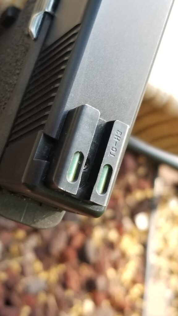
Well, trying to take a photo in the dark of three green dots with a cell phone camera was an experience. I went in a basement room and shut the door to cut off light. It’s fuzzy but you get the idea – all three dots are nicely lit in any lighting condition.
Do they have lower cost models also?
Yes, they do. The Tritium series just has the tritium for illumination in the dark and show as bright white dots during the day.
They also make a Tritium Pro series that builds on the Tritium base model and adds an orange ring to the front sight plus the back sight is bigger and that makes it easier if you need to rack the slide with one hand.
I find these sights to be an incredible improvement over the plain Glock sights – they are easy to see and aid with rapid aiming. I really do like these sights and use them personally. I strongly recommend them.
I hope this helps you out.
Note, I have to buy all of my parts – nothing here was paid for by sponsors, etc. I do make a small amount if you click on an ad and buy something but that is it. You’re getting my real opinion on stuff.
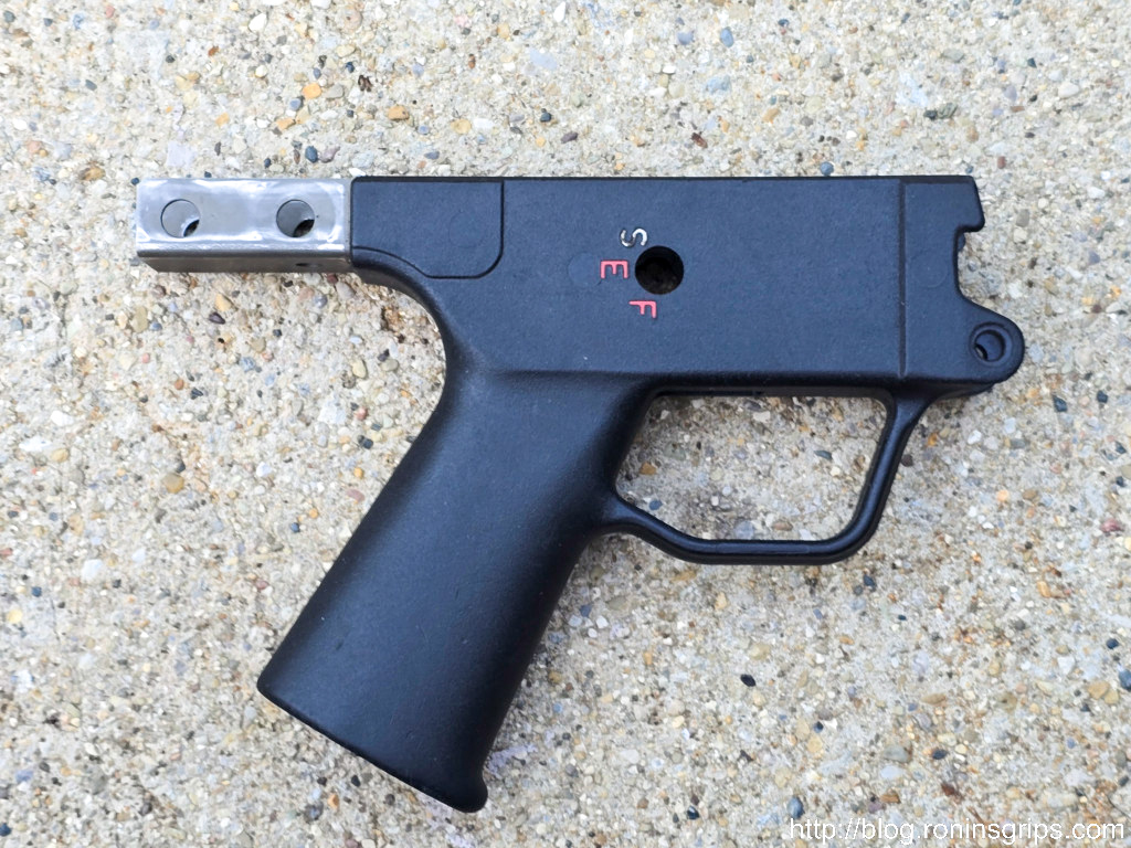
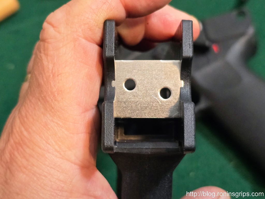
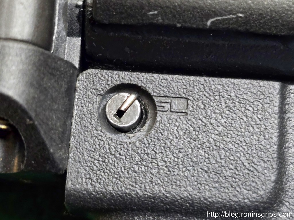
Grips for the MP5/HK33 and HK91/G3 rifles can be converted for use on MP5K-type weapons. As you can see in the photo above, a small circle appears at about 2:30 position on the larger hole for the pin when this is done. I used to wonder why and since I started offering converted grips for sale, I’ve had a few guys also ask me why this is the case.
Well, the short answer is that the steel reinforcing that is cast into the rear of the grip has different holes when an MP5K grip is made vs. the others. This allows the hole for the pin and the countersink for the head to not encounter another hole.
This is a real German H&K MP5K grip. The top rear hole doesn’t have that telltale circle of conversion because it was purpose built to be mounted on a MP5K.Not one of my better photos but you can see the pin hole on the far side. The anchor holes to secure the metal strap are to the left and right of it are filled in with plastic during injection molding. Notably at the rear right there are two anchor holes to help compensate and secure the strap.
With the MP5/HK33 and HK91/G3 grips, the designers never planned for a hole to be made in that location and as a result, the newly drilled hole runs right into an anchor hole they have in the metal to allow the injection molding to adequate bond to it.
If you try to drill into one of these grips, the smaller hole will get cut open and then ride the flute of the drill upwards and make a mess. To compensate for this, an end mill must be used to do a plunge cut straight down. There must be careful workholding fixtures to keep the grip from moving. Trust me, I’ve trashed a bunch of grips by not making sure the grip was completely secure.
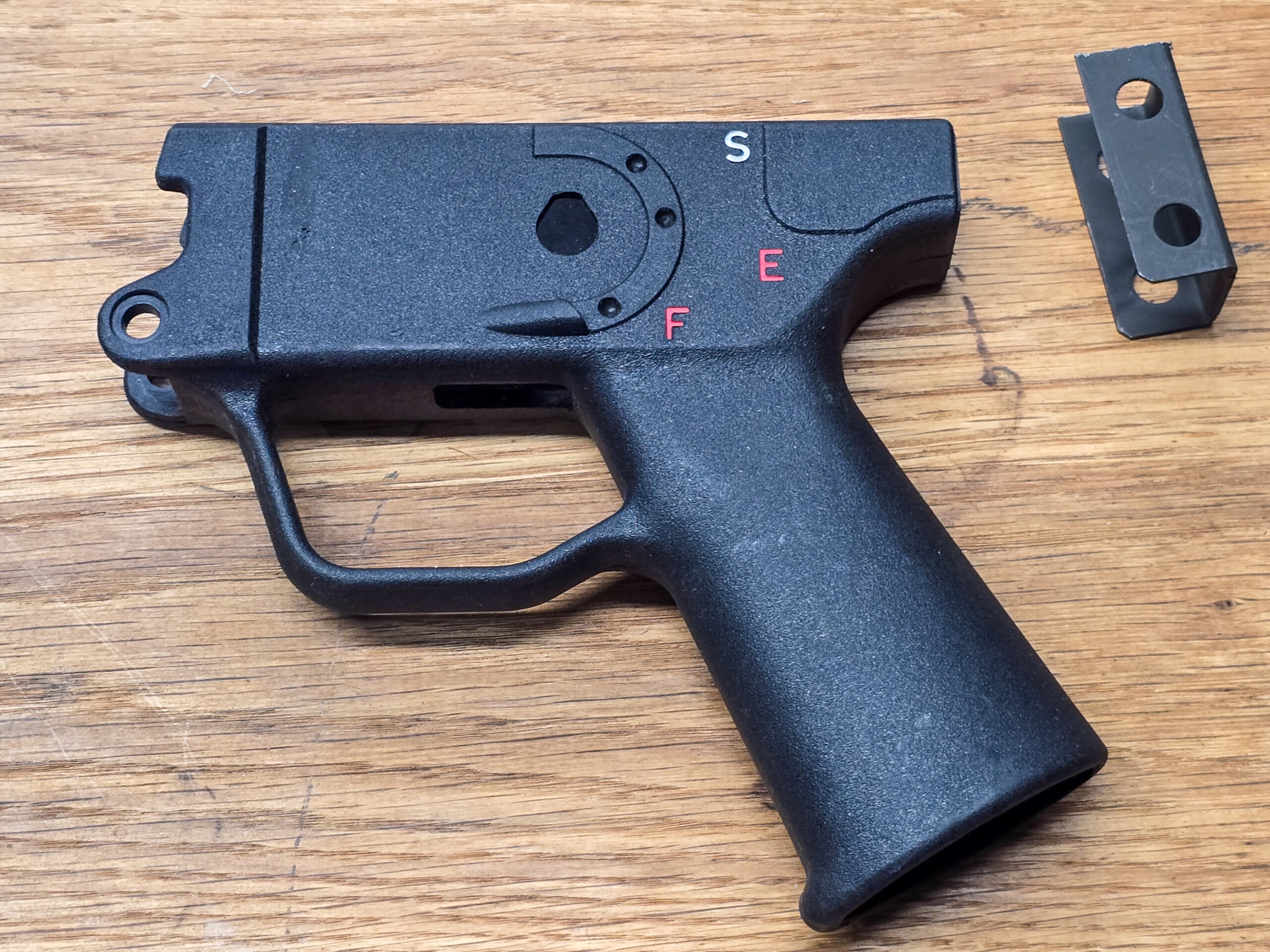
This HK33 contract grip has anchor holes that go evenly across. There isn’t enough spacing between those holes for a new 6mm pin hole and 9.5mm countersink to be milled without hitting the rear anchor hole.This is a Malaysian contract grip that has the rear steel “tail” cut off. Both pin holes and countersinks have been milled. Look at the hole on the right. The pin hole ran right into the anchor hole and tore out the plastic that would have filled it. By the way, the orange paint was from me tracking early prototypes. It’s not something someone would normally see.
Despite those rear anchor holes being removed, the steel reinforcing is still held in place. While theoretically weaker, I have not heard of any real world cases where the the steel (it’s folded sheet metal really) has come lose due to separation from the surrounding polymer.
For people using converted grips, just insert your rear pin such that the retaining wire is on the shoulder and not in the hole. That’s really the only difference. Of course, like most grips, some final fitting may be required – by using a circular file to adjust the rear hole, filing the front locking plate or removing a bit of material off the back with a file or by sanding.
Summary
In short, purpose built MP5K grips have enough spacing between the rear metal strap’s anchor holes for the 6mm pin hole and 9.5mm countersink to be drilled. Other HK models do not use that same spacing so the tell tale partial hole appears at the 2:30 position. It’s purely cosmetic and just requires the user to insert the rear pin such that the locking wire rests on the normal shoulder of the hole and not the newly formed void.
Do you have an old HK grip, or any other plastic item, you want to rejuvenate? Or maybe you bought one of the contract grips, washed it and now it’s a dull grey and all of the scratches stand out and you want to make it look better? It’s easier than you might think.
Clean the grip
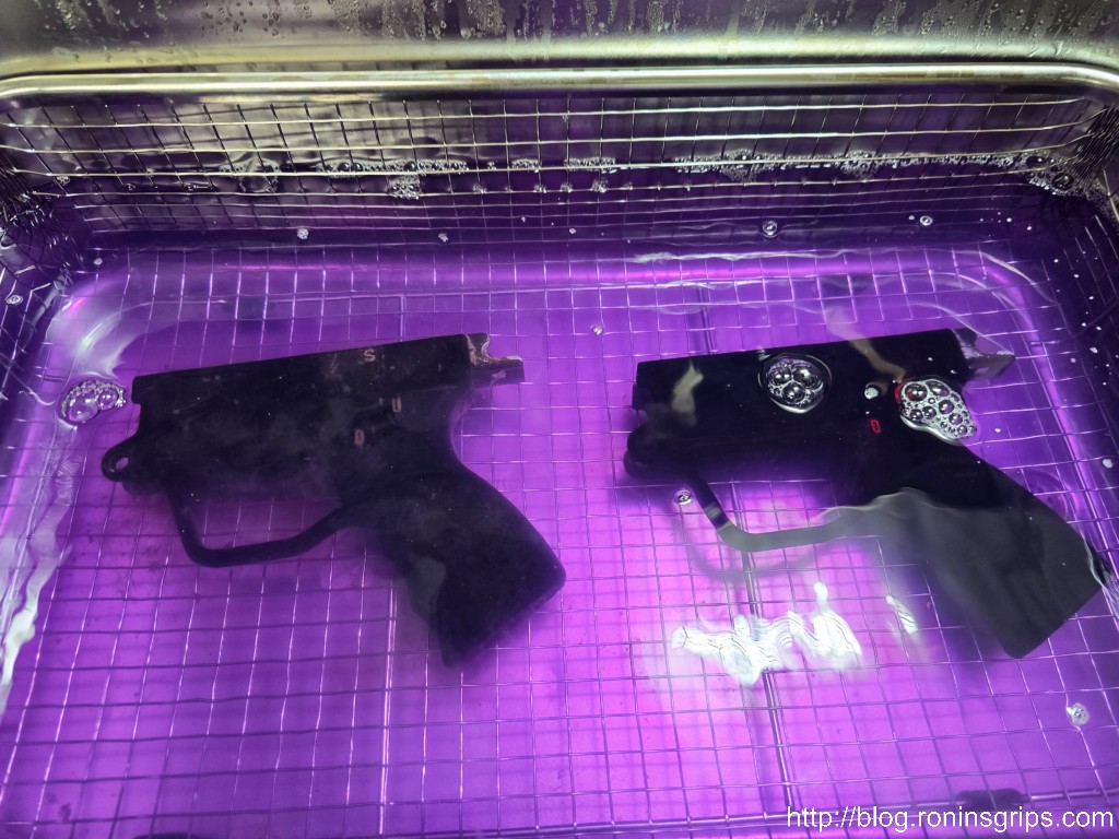
I recently boought a bunch of the the surplus HK33 “contract grips” that were made by SME Arms and Ordnance manufacturer, Malaysia under license from HK and most of them really needed cleaning – everything from cosmoline to brown masking tape with numbers were on them.
The first thing is to really clean the grip. I use a Vevor 30L ultrasonic cleaner[click here for a review I did on mine] with Simple Green HD and water in it but you can use any warm-to-hot soapy water and something to scrub with to clean it up. Use compressed air to blow it dry real quick before any exposed steel surfaces rust.
These HK33 grips are a mess. Most are beaten up to some extent. Many were covered in cosmoline – that grip on the top that is shiny is coated in it. Some even had old dry masking tape wrapped around the actual hand-grip portion.
If you aren’t interested in ultrasonic cleaners, you can also have very good luck with hot soapy water. I used to recommend brake cleaner but that has really lost its cleaning power as various regulations have really reduced its strength.
This is a 30 liter Vevor ultrasonic cleaner filled with Simple Green Pro HD heated to 158F (70C). It gets rid of pretty much everything in 15 minutes including most if not all of the paint in the lettering.
Dealing with scratches and small nicks
Major repairs can be a challenge. Filling them with black epoxy or black super glue creates visible repairs. Black super glue to close a clean crack works surprisingly well. Starbond makes a black super glue that is superb at closing cracks plus bonding clean surfaces together in general – click here to see it at Amazon
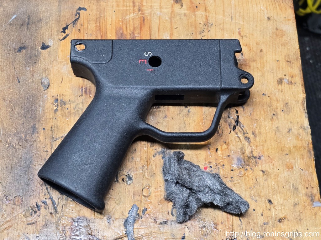
For minor scrapes and scratches, the best approach I have found is to use 0000 (sometimes called “quadruple ought” or super fine) steel wool and vigorously rub down surfaces to get rid of scratches and any plastic sticking up from getting nicked. The benefit I have found with it vs. sandpaper is that it doesn’t destroy the surface finish as easily.
This is an actual HK German SEF grip converted for use on an MP5K. I used 0000 steel wool to knock over any sticking out plastic and reduce minor scratches. I find careful use of steel wool helps me improve the surface some without destroying the pebbled finish on the plastic.
Restoring the black color
Black plastic fades as the surface layer loses its oil/moisturizers. The trick to try and replace those lost chemicals and bring the color back.
Black plastic that has been ultrasonically cleaned is greyish and you can see all of the scratches. If you don’t know it’s coming you can have a “what just happened” moment.
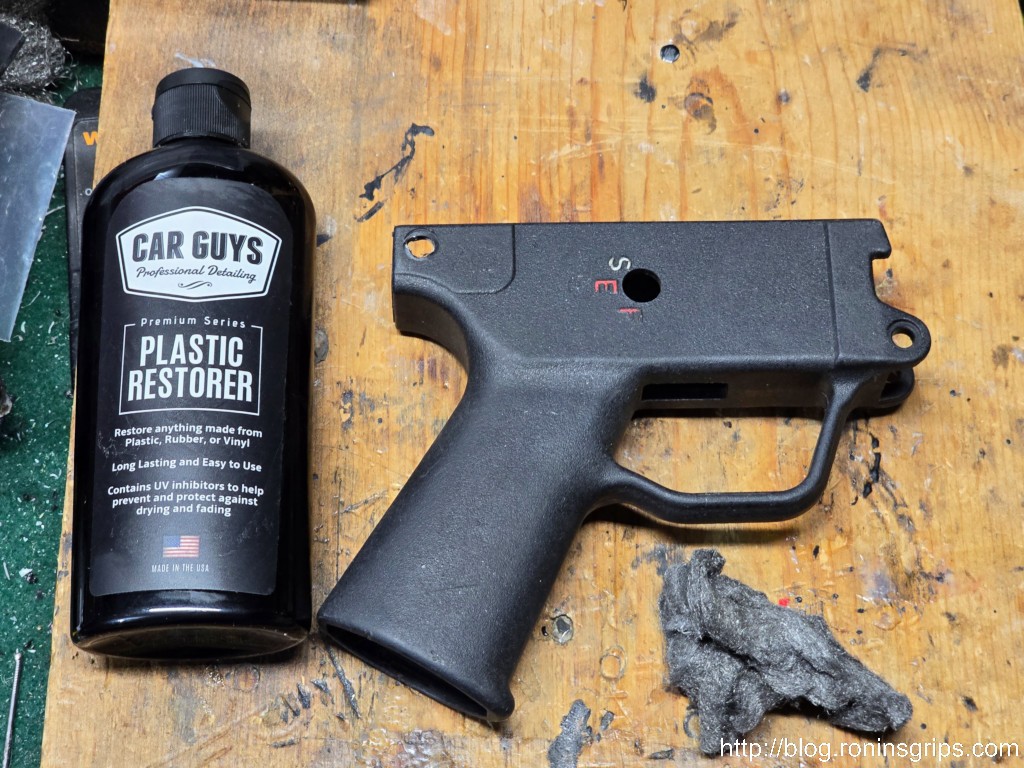
The treatment I use is made by Car Guys and is called “Plastic Restorer”. Again, make sure the grip is clean and then rub this stuff in. I use nitrile gloves and work it in. You want a thin film there. I let the stuff sit overnight and buff it off with a shop towel the next day. It does a nice job and will last for sometime. I’m not exactly sure how long – I’ve been using it for almost six months and nothing has faded yet.
On this HK SEF grip, it’s been cleaned and I used steel wool to knock down any rough spots. Next up is applying Car Guys Plastic Restorer.The actual cream that comes out is an odd blue grey color. I wear nitrile gloves, put the cream in my glove and then apply enough to leave a film. It does need to have a light film – not super thick but something like this. It has to sit to work, I try to let it sit overnight if I can. They say at least 10 minutes but I find the longer the better. You then wipe it down and remove any residue on the surface,This is the same grip. It sat overnight and then I wiped it down the following day.Same grip – other side.These are four of the grey ashen grips shows above after following this process.Same grips – the other side.
Summary
I did not know why black colored platics fade with time. Now I do and the Car Guys Plastic Restorer works on more colors than just black. Click here for it on Amazon – there’s a reason there are over 31,000 reviews and a score of 4.4. It’s that good. So, whether it’s plastic on firearms, cars or something else, this stuff might really help you bring the color back.
One perk is that it does seal and provide UV protection after it is applied. I’ve been using it for six months and nothing has faded yet but then again, no finish lasts forever so I would bet that some day I will need to touch things up.
Note: This stuff isn’t for headlights and it doesn’t fix physically damaged plastic when there is a thick crust of oxidation or scratches. It’s meant to bring the color back is all.
I hope this helps you out.
Note, I have to buy all of my parts – nothing here was paid for by sponsors, etc. I do make a small amount if you click on an ad and buy something but that is it. You’re getting my real opinion on stuff.
There are some things I like on MP5Ks and some things I don’t. I usually dislike the triggers but my MKE AP5-P has a fairly decent trigger as MP5 and MP5Ks go. My MKE also had a factory contoured grip. Of all the HK grips out there, the contoured is the one I like best but there is one I like even more – the “Magpul SL Grip for HK94, HK93, 91 and Semi Shelf Clones”. That one heck of a long product name – just remember the model – MAG1070-BLK.
This is the Magpul “SL Grip Module for HK94/93/91/MP5 & Semi Shelf HK Clones” – Model MAG1070-BLKZenith ZF5-P. Very nicely made pistol. Relatively bland grip.Century Imports’ MKE AP5-P. It’s excellent. I like the contour grip more but that’s a personal preference.
A few months ago, I installed one on my Zenith ZF5-P and really liked it. Whereas the MKE has a contoured grip, the Zenith has a basic straight grip that is only slightly more ergonomic than a rounded rectangle. I’d read a few posts about guys converting over the Magpul grip, so I did the same. You know what? I realy like it.
Here it is on the Zenith. By the way, that is Magpul’s cool ESK Extended Selector Lever. I have links to them at the bottom of the post.Here’s the second one on my MKE AP5-P.
Doing the Conversion
The Magpul SL grip wasn’t designed for use on a MP5K but what you need to do is pretty straight forward if you have the tools and at least some basic knowledge of locating holes to be drilled.
Let’s go over some basics – first off, the steel “tail” that sticks out of the Magpul will need to be cut off. I’d recommend using something like a hacksaw, reciprocating saw or a bandsaw. I have a metal cutting bandsaw so I used that. Please notice I did not list a Dremel or similar rotary tool with an abrasive wheel. They risk making the steel so hot that the plastic could be damaged.
The first step was to cut off the tail. I did it flush with the end of the plastic and cleaned it up with a belt sander.
Next, sand the tail end smooth. Take off as little material as possible as it will help you get a solid lockup.
Take off as little material as you can until the grip fits and the end cap, brace or stock can fully seat. By the way, I should have cleaned up a bit more before this photo – the dust you see if from me sanding Hungarian Grey-Blue AMD grips that we make. The dust is not from the Magpul grip – it will be black flecks of plastic and a bit of metal from the steel reinforcing channel inside the rear.
As you may have noticed, many MP5K-type weapons, such as those from MKE and Zenith, use two small pins to retain the grip assembly – one in the front at the bottom and one in the top rear. With the semi shelf and a snug fit, you just need the single rear pin to hold the grip’s rear end up and in place.
The front of the grip has a plate that interfaces with the semi shelf on your MP5K. Magpul includes instructions for SP5 owners that they may need to remove a little material for a good fit and I would assume this extends to the SP5K but I don’t know this for sure. With both my MKE and Zenith, no adustment was needed.
That little rectangle welded just to the right of the front grip pin hole is the semi shelf.This is the locking plate for the grip that interfaces with the semi shelf at the bottom slot in the photo (if the weapon were held upside down, it would be the slot at the top .)
In terms of locating the hole, take your current grip and measure backwards from the front locking plate to the center of the hole. Then, measure down from the top of the grip. Use these two measures to locate where you need to do your cutting and then setup your mill accordingly or at least a good drill press because all you are doing is plunge cuts.
Measure the hole from the locking plate to where the center of the hole is on your existing grip – this is the horizontal measure. I’d recommend using calipers to do this. You then need to do the vertical location by measuring from the top of the grip to the center of the existing hole. The more precise you can be, the better your results will be.
Cutting the rear hole.
Critical: You must make an insert from hard wood, plastic, or aluminum. If you don’t, the walls of the grip will flex and your holes are going to be a mess. I learned this the hard way. The width left to right is about 7/8″ and then you can decide how you want to handle the vertical. I’d recommend surrounding the area where you want to make the cut. I run my insert the whole length of the inside top to provide a firm support both for the clamps and the plunge cuts. You don’t wany anything to flex.
If you don’t have an insert to keep the grip open, they will flex as you attempt to cut them and you’ll make a mess. This is 7/8″ left to right. I then made it the length I wanted. The “leg” on the left bottom is to help it stay in position in the grip. The hole on the right shows you where the 6mm end mill plunges into it.
The first step is to cut the reliefs where the pin goes. The head of the takedown pin is about 9-9.1mm wide. A 9.5mm cut doesn’t give you much room to adjust. 10mm is just a tad wider and gives you more room to adjust your cuts later with a circular file and not have the head unable to sit down in the recess. The reliefs need to be cut about 3mm deep.
That is a 10mm end mill and I just finished a 3mm deep cut. A 9.5mm head would give you a tighter fit around the head of the pin but 10mm gives you some adjustment room.
Next is to cut the 6mm holes for the pins. I’d recommend against a drill bit as it might get squirrely on you – both in terms of deflection or the bit getting caught on one of the holes in the steel reinforcement. Get a 6mm carbide end mill, make sure your grip is held securely and do a plunge cut.
A 6mm end mill was used to plunge cut the center hole for the pin.Here is the MKE Pin with an OD head diameter of 9.1mm. The countersink was cut 10mm wide and 3mm deep. This gives a bit more room for adjustments.
If you do use a drill press, check your runout. If you have more than 0.5mm on one side, you risk cutting to big of a hole. You want to be somewhere between 6.0 and 6.1mm. If you go too wide, the retaining wire may not get a good enough hold to keep the pin in place.
Cleaning Up
Use a fine file or diamond abrasive stick to remove all material left over from cutting inside the grip so you have a smooth surface.
It’s time to test fit the grip. It may go in great all by itself or you may need to adjust it just a tad with a circular file. I’d recommend a 6mm tapered circular file so you have a lot of control.
This 6mm tapered Bahco file is great for adjusting holes. Click here to see it on Amazon.Use a circular file to adjust the grip until it fits. Don’t rush – take off a bit and test, take off a bit and test until it fits. That is the Bahco 6mm file I mentioned earlier. It’s great for this kind of work.
Note, test fitting the grip by itself is one thing. Doing it with the stock, brace or endcap in place is another. You may find further adjustments with the circular file are required. Also, you can make things fit sometimes by moving or tapping the grip or whatever is on the end around. The sheet metal of the receiver can flex and sometimes it gives you just enough alignment to push the pin on through. I often tap (not bang) them in with a small hammer with a non-marring head.
You want everything to be snug. You’ll find the front pin doesn’t matter if everything is tight. If you really want a front pin, you would need to make a custom pin given the width of the Magul’s front lower “ears”. It would also only be cosmetic because you would be inserting a steel pin into soft plastic that does not have a reinforcing plate.
The moral of the story is to keep the front-to-back length of the grip long so it is snug – again, don’t cut or sand off more of the black plastic than you must. Also, try to be as close as you can with the pin holes at least vertically. Because of how the grip is sandwiched between the mag well and whatever is on the rear, it’s not going anywhere. The rear pin is the final part to limit movement.
I used the file to slot the hole backward just a bit. Note how tight the grip is up against my SB Tactical brace. It’s not going to wiggle.
The Results
The MKE feels great. I will upgrade the selector the Magpul ESK but even with the stock MKE selector I like the feel more.
Summary
I hope this helps you out if you want to do this yourself. For folks who just want to do the final filing adjustments, we will converted Magpul grips for sale. Please click here to go to our store.
Here are the original Magpul grips in case you are looking for them:
Production Grip Comment
For our production grips. the holes are based on a new unissued German MP5K grip. Depending on a bunch of factors, the exact holes in the grip you get will vary a bit. Fitting will be required – front to back and the hole locations.