Category Archives: Firearms Building and Gunsmithing

How to build and/or gunsmith on certain platforms.

Fixing a Bent Sight and Cocking Lever Tube Bur On The PTR PDWR

Okay, when I received the PTR PDWR I did a quick inspection and noticed two small problems that needed fixing.  I’m a bit disappointed that PTR quality control did not catch these two items but they are small issues.

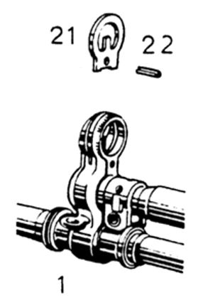
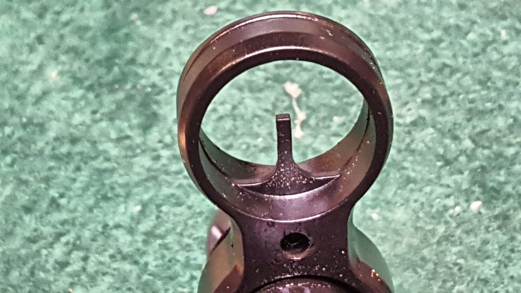
First, the front sight blade was bent sideways – to canted, bent.  I’m not sure how this happened but thankfully the HK-style hooded sight uses a sheet metal insert for the front post.  The following illustration is from the HK G3 Armorer’s Manual:

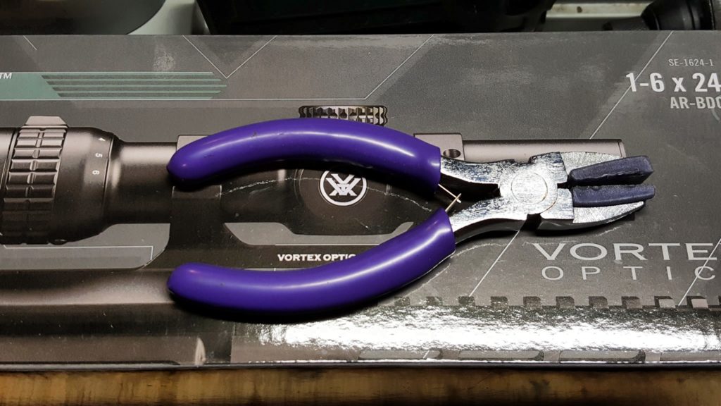
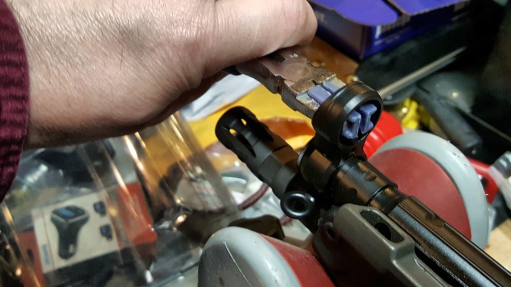
I figured the easiest thing to try was to simply reach in with pliers with padded jaws and see if I could simply bend it to the right to straighten it.  Out came my purple art pliers 🙂  I literally bought these things back in 2013 for some kind of work that required padded jaws.  I don’t recall what and as odd as they look, they have held up to light use.  My only complaint is that the nylon jaw covers can slide off under very much stress but that was not an issue here at all.

They actually fit perfectly and I was able to bend the sight post straight.  Plan B would be to take a pair of needle nose pliers and slide rubber fuel line hose over the jaws.  My one concern would be whether the relatively thin jaws could adequately support the post during bending.  The art pliers below fit and did the job perfectly.

Fixing a Bur on the Cocking Lever Tube

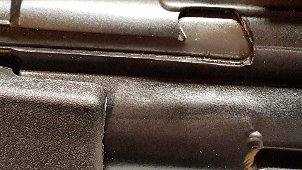
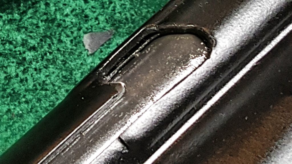
The second problem I needed to fix was a steel bur on the tip of the cocking handle catch.  It bugged me every time my hand hit it and should not have been there.  Here it is in the next photo – sharp and pointing out.

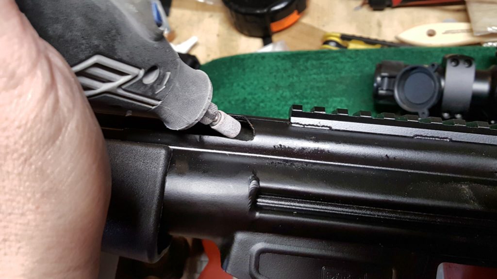
In terms of the repair itself, first, I reached in with a Dremel using a small medium grit sanding drum and the tool on slow speed to knock down the sharp irregular edge from the inside.  Take your time – remove a little and look.  Your goal is always to remove as little material as possible.  As the old saying goes, it is easier to take more off than try and put it back on 🙂

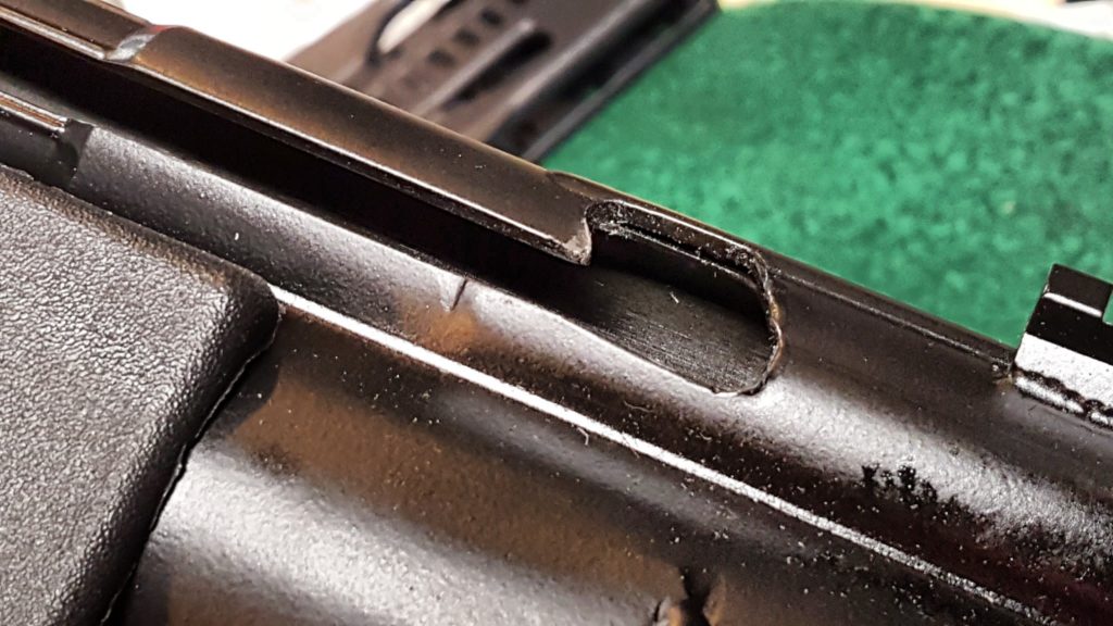
In the next photo, you can see the “point” has been sanded down but there is still material on the surface:

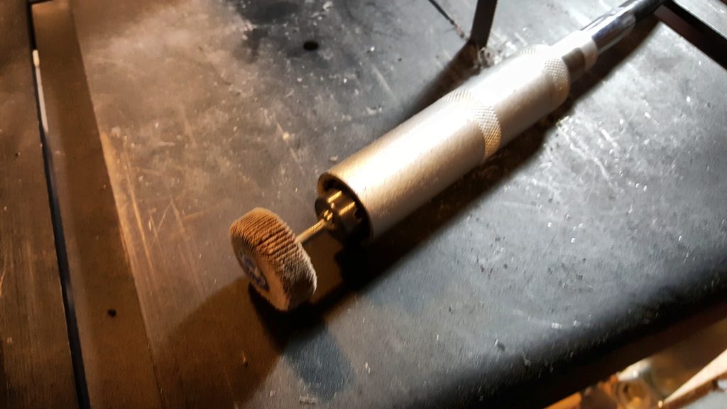
Next, I used a 120 grit small flap sander in my bench mounted rotary tool to sand down that lip.  I could have used my Dremel but I use the little flap sander attachment so much that I routinely leave it in my bench tool.

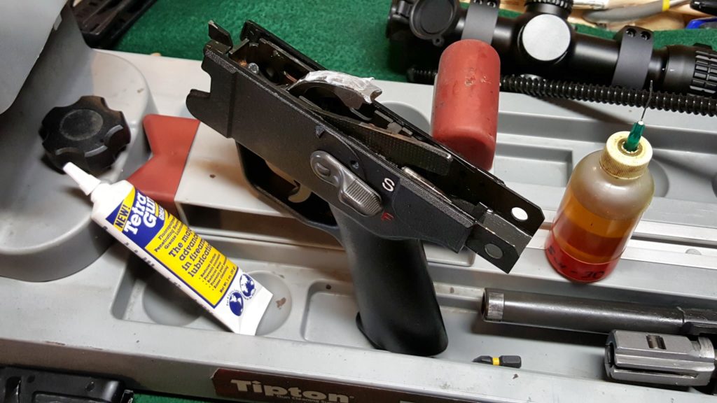
Again, the trick is to go slow and take your time.  After that, I used compressed air to blow out the tube and receiver and then used carb cleaner spray to “wash out” anything that might have stuck and blew it out one last time.  The bur was gone and now it was on to lubricating the weapon.

(Note, that last photo above has the bolt back in when I was testing it later).


If you find this post useful, please share the link on Facebook, with your friends, etc. Your support is much appreciated and if you have any feedback, please email me at in**@ro*********.com. Please note that for links to other websites, I may be paid via an affiliate program such as Avantlink, Impact, Amazon and eBay.


Adding a Vortex 1-6×24 Strike Eagle Scope to the PTR PDWR

I really prefer an optic on my firearms at this point.  The PTR PDWR is a relative short range pistol so I figure post of my shots will be within 100 yards.  It could certainly shoot further but, based on what I have read so far, the accuracy goes down hill fast.

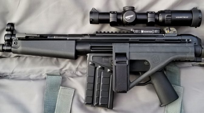
While some might consider a red dot, I opted for a true 1-6×24 Vortex Strike Eagle scope that has a 30mm tube.  Now, I have to admit that I have become a bit of a scope snob over the years.  I’ve destroyed cheap scopes, suffered with dark images, short eye relief and what not.  About four to five years ago I happened upon Vortex and they have been my go to brand ever since – not only is the quality there but they back it up with a no-nonsense warranty.

Folks, I’ve owned probably at least a dozen Vortex scopes and red dots.  I still have six that are on firearms that I plan to keep.  I have had zero problems – not one.  Not out of the box and not over time.   I probably will some day – stuff happens.  I’ve talked to other guys who broke their scopes (literally) or had problems and sent them in with Vortex taking care of them no questions asked.  That says a lot.

So, that brings us to the scope.  The Strike Eagle is a decent entry-level AR scope with an illuminated reticle.  I bought this scope about a year ago for a project that didn’t happen and it has been sitting on the shelf.  The good news is that Vortex now also has a 1-8×24 model.

Mounting the Scope

I used to use cheap import cantilever scope mounts but have since stopped due to screws stripping out and easily scratched finishes.  I now use Vortex mounts pretty much exclusively now as well.  I know I sound like a salesman but I really like their stuff.

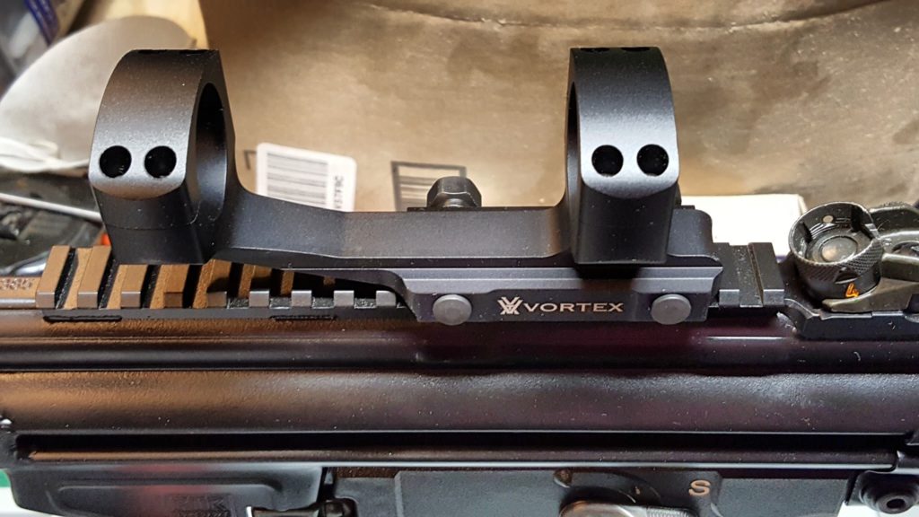
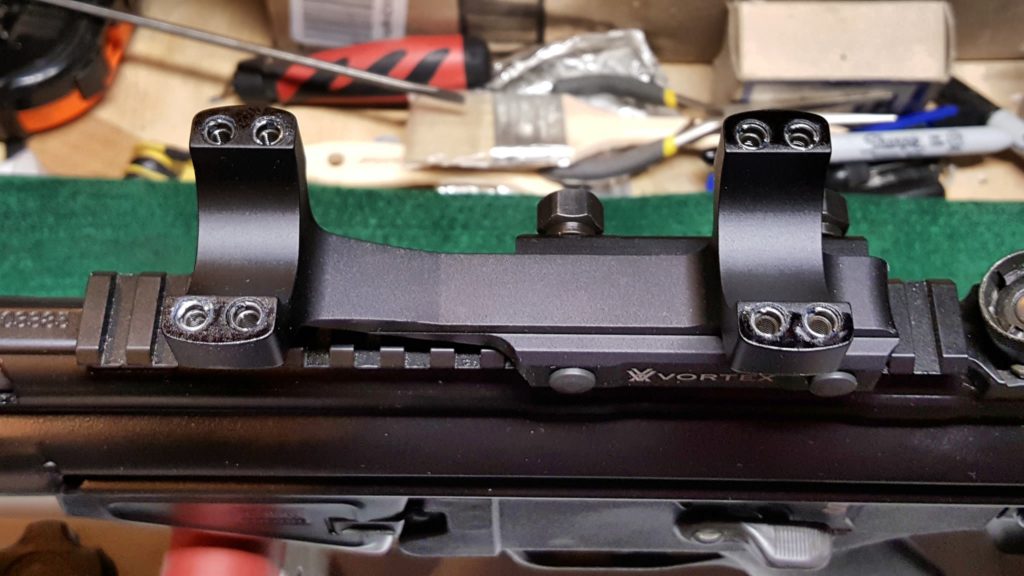
You’ll notice the quality of the finish and that the parts are beefy.  You can go 18 inch/pounds on the rings and 65 inch/pounds on the rail attachment nuts.  You’ll notice that cheap scope mounts don’t publish torque specs usually because they can’t handle much consistently.

The ring caps are secured by screws that have heads for #8 Torx bits.  They go into steel threaded inserts for added strength – you will not find steel inserts in cheap mounts by the way.  At any rate, lets begin.

Safety First:  Make sure your weapon is unloaded!

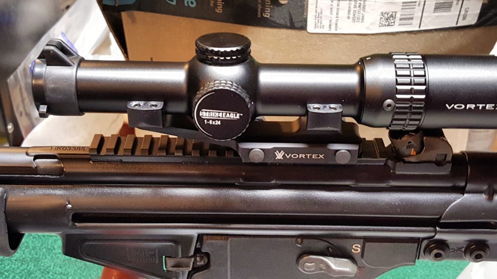
As you can see in the above photo, I located the mount on the PDWR’s Picatinny optics rail a few grooves forward of the rear sight.  It was a bit of an arbitrary point.  I know I usually am near the rear plus on my past HK-style weapons I knew I might have to work around the rear sight.

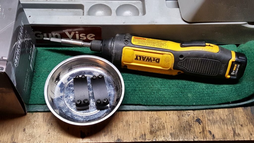
I removed the ring caps using a #8 Torx bit from my Weaver screw driver set and put them in a magnetic parts tray.  I have lost little parts in the past so I am a bit paranoid now.  I use my DeWalt cordless screwdriver to do the removal work as the twisting motion of a screw driver really messes with my carpal tunnel.

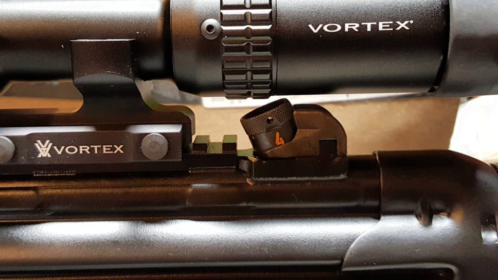
Next, I place the scope on the rings and the very first thing I check is the clearance over the rear sight.  In this case you can see the scope clears it.  Years ago with my first rifle, a GSG-522, I scratched a scope by not checking that before I started screwing down the rings.

Next, I install the ring caps back on.  A time saver I do is to use the Dremel to run the screws in but there’s a trick.  Hold the screw driver lightly so it can run the screws in but the screw driver turns in your hand the second it bottoms out.  You don’t want to apply torque – just run the screws in.  I then back them off just a bit so I adjust the scope in the mount.  I also adjust them in or out slightly so I can get any gap between the ring cap and the base equal all the way around.

I then shoulder the rifle and move the scope forward and backward until I get the proper eye relief.  You want to be able to pull the weapon up quickly and see through the whole scope vs. having to move your head around to get a good sight picture.

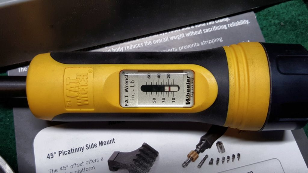
Also, I true the scope left to right.  If I were doing a precision rifle, I would do it differently but with the PDWR, I eyeballed the reticle relative to the position of the rifle to level the scope and then tightened down the ring caps.  I like to carefully take them down snug all the way around and then set the torque at 18 inch pounds with a Wheeler Fat Wrench – note that Fat Wrench does not have a clear 18 in/lbs setting so I try to get it close.

The FAT wrench does a good job. There is now a digital model too and you can find both on Amazon.

Once you are set, you also need to torque down the mount’s rail attachment screws to 65 inch pounds.

I was taught to never store a torque wrench under load so once I was done, I then adjusted the Fat Wrench back to zero.

At that point you are done.  While setting up the optic and installing the brace, I noticed some tuning was needed and that will be the next blog post.

Click here for the post about installing the SOB arm brace

Click here for the post about selecting and purchasing the PDWR

Summary

The Vortex optic worked great on the PDWR. Vortex makes tons of scope and red dot models – I recommend them all because Vortex stands behind what they make. Click here to see a list of Vortex Optics currently for sale on Amazon.

I hope this helps you out.


Note, I have to buy all of my parts – nothing here was paid for by sponsors, etc. I do make a small amount if you click on an ad and buy something but that is it. You’re getting my real opinion on stuff.

If you find this post useful, please share the link on Facebook, with your friends, etc. Your support is much appreciated and if you have any feedback, please email me at in**@ro*********.com. Please note that for links to other websites, I may be paid via an affiliate program such as Avantlink, Impact, Amazon and eBay.


Adding a Brace and Changing the Forearm on the PTR PDWR

In the last blog post, I talked about the specifications and ordering the PTR PDWR.   Even before it arrived, I knew I wanted to add a brace.  My plan was to use PTR railed handguard and I had a “wait and see” attitude towards the brake.

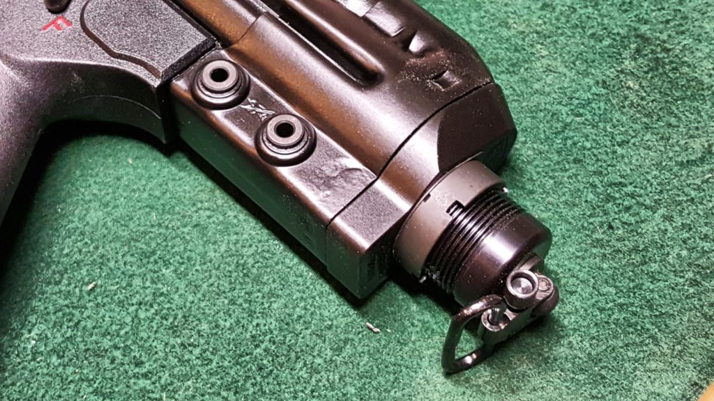
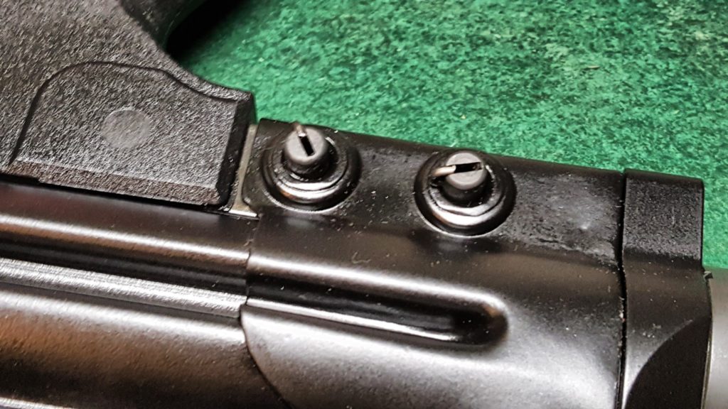
So, the first step was to remove the existing end cap.   In HK-type weapons is is held in place by two push pins that are simply pushed back out.  You’ll notice that one side is relatively flat:

The other side will be protruding and this is the side that you push on and will remove the pins from the other side:

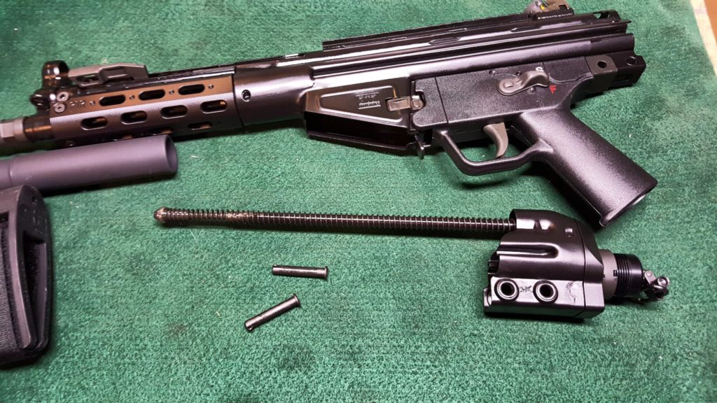
You then wiggle the end cap and push it off the end of the stamped receiver.  It will look like this:

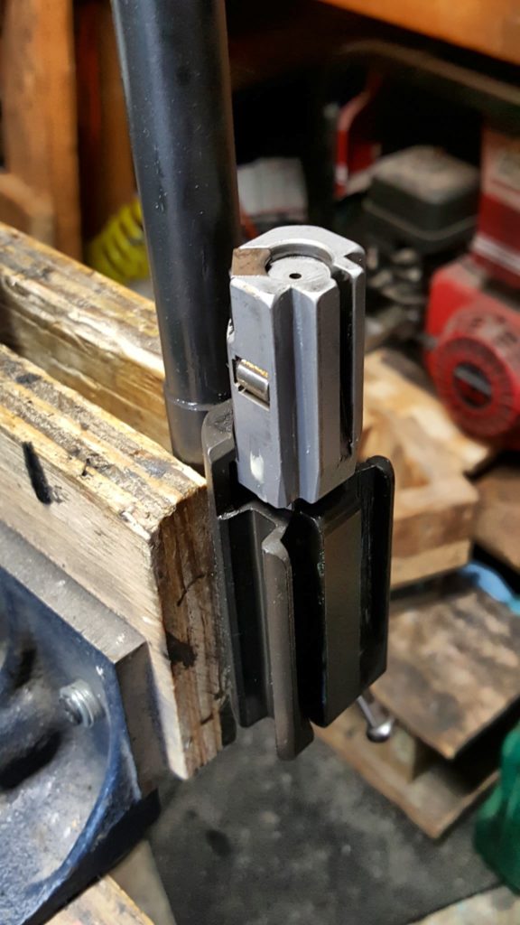
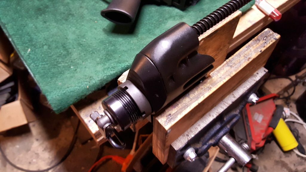
I then secure the end cap assembly in a vise to make working on it easier.

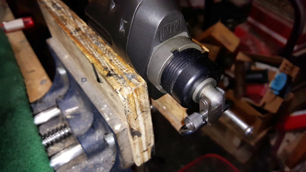
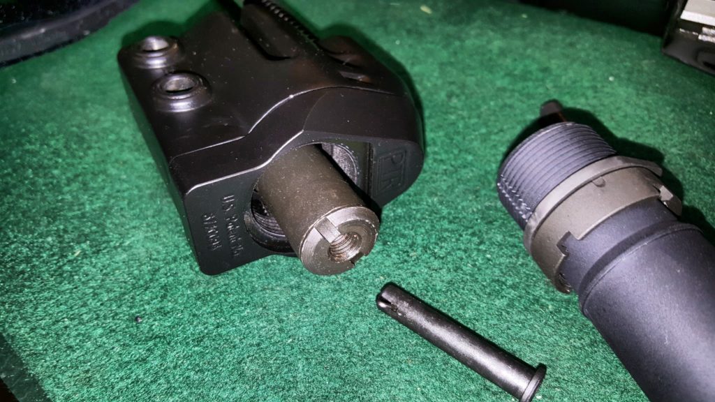
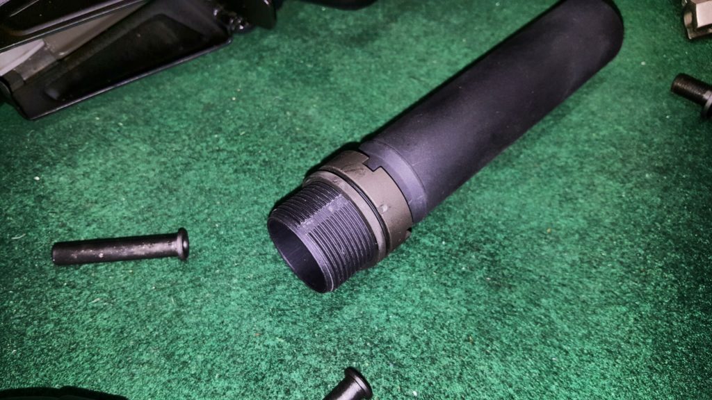
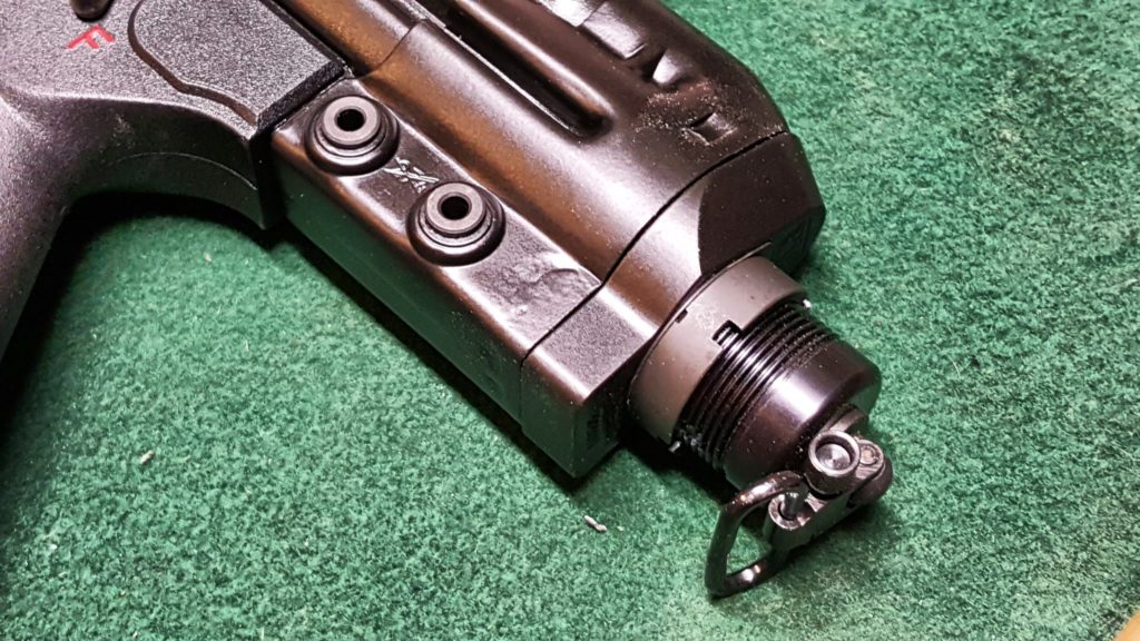
In the next photo you can see how the tube and sling really are like a small stub of an AR/M4 buffer tube complete with an indexed end plate to keep it from rotating and a castle nut.  The swivel is separate from the tube and is threaded into place so unscrew and remove it first.

In the next photo, you can see the lighter grey castle nut on the black tube.  The light grey surface you can see in the otherwise black cap is the plate you will need to fish out after you back off the castle nut.

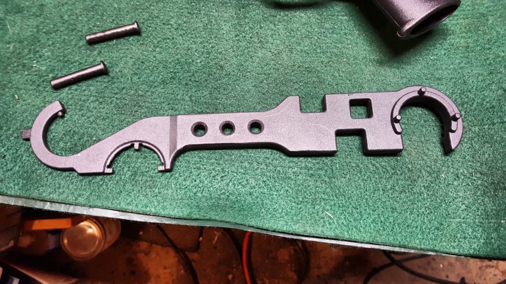
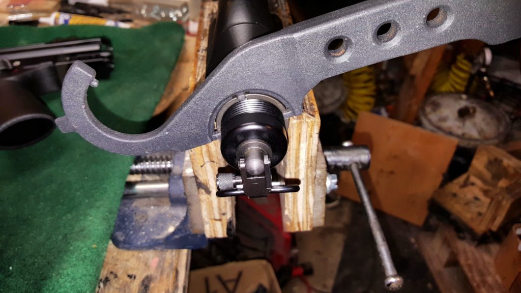
To remove the tube itself, you do the exact something you would on an AR.  Use a castle nut wrench to loosen the castle nut and then thread it back out of the way.  Then pull the end plate out of the receiver so it can rotate and then turn the tube to remove the assembly.

In the next photo you see the castle nut wrench on the tube with the sling.  I realized shortly after this was taken that I probably needed to get the sling off before I could back out the tube – that is why I said remove the sling first.

As written above, you will need to pull the end plate out of receiver to be able to turn the tube.  With the plate pulled out from the receiver, the tube simple unscrews.  If it does not want to unscrew, make sure your plate is out of the way.  Also in the next photo, you can see the very secure mount that the sling screw threaded into.  That was well thought out.

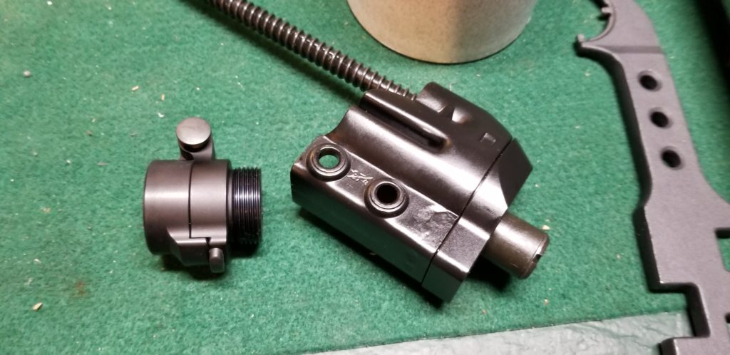
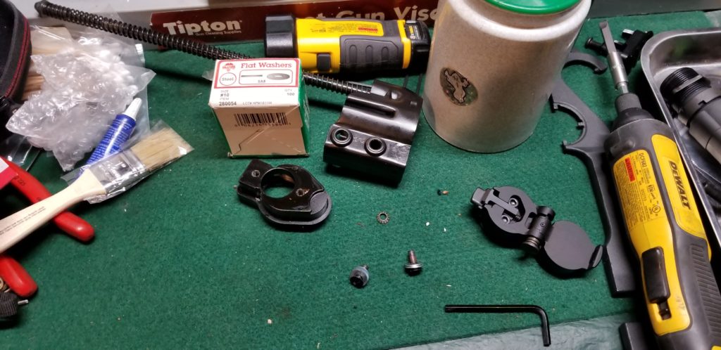
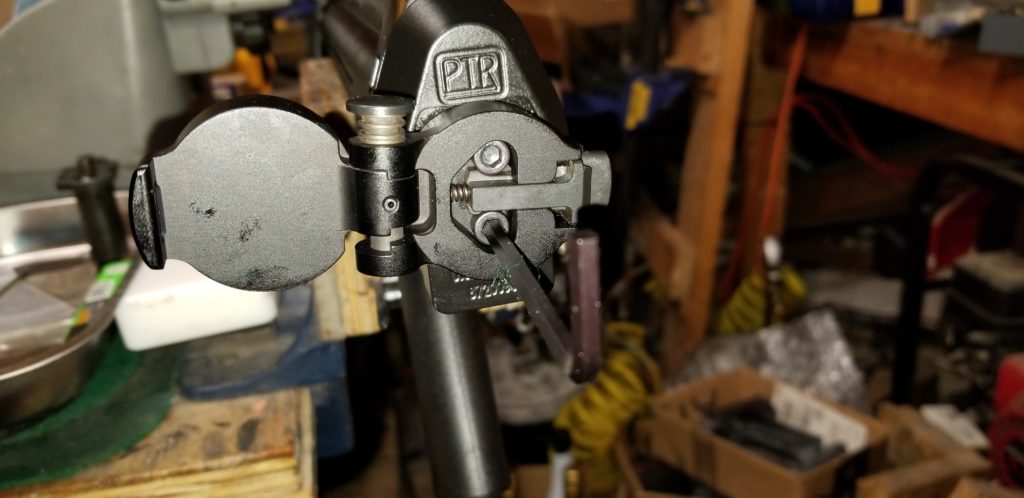
Next, I wanted a folding mechanism to be inline between the receiver cap and the buffer tube.  SBTactical makes a very sturdy 6061 aluminum unit known as the “BTFA”.  To install it meant the tower that the sling swivel screwed into needed to be removed.  It adds about 1.1″ to the length when installed.

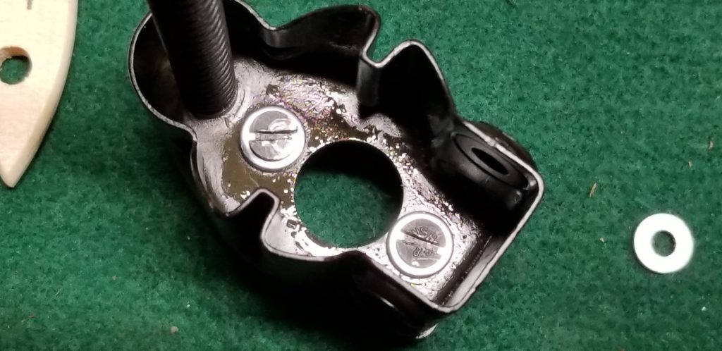
The tower is held in place by two screws inside the cap.  Mine were beat half to death – the assembler at PTR must have figured nobody would ever notice.  He/she was wrong and I was disappointed that they had installed the screws with an undersized blade screw driver and tore up the slots.

Once I removed the tower, I just inserted three #10 washers between each of the screws so the aluminum end cap and the sheet metal assembly would all come back together nice and snug.  If I wanted to take the time, which I didn’t have, I should have found some of the correct size button head socket screws and replaced the beat up countersunk originals.  So, what I had looked like this and the screws were a bear to get in (Yes, I did use the correct size screw driver to put them back in.)

Putting it Together

The BTFA install is very simply.  Use the supplied allen wrench to loosen the disc assembly that is the threaded plug that goes into the receiver.  Do not remove them all the way – you just want to loosen it up so you can screw in all the thread and adjust the folder to the direction you want.  I wanted the stock to swing to the left to lock out of the way of the ejection port.  You then tighten down the allen screws back down.

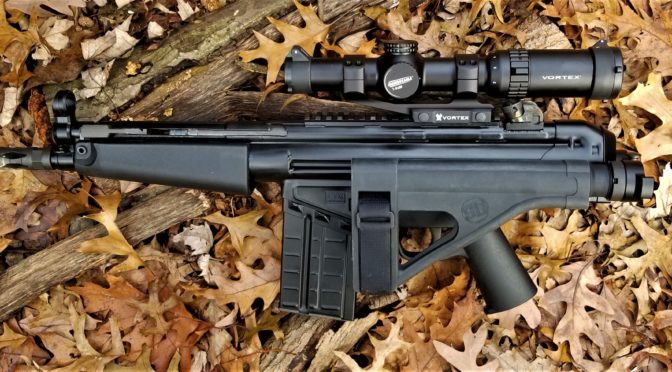
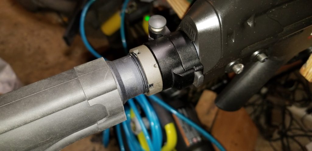
I installed an SB PDW tube and an SB SOB (love that acronym) brace.  Now, to install the tube, I reused the PDWR’s end plate to and a new castle nut that came with the tube.

To install the buffer brace on the tube, I spray silicone on the tube so it can slide on way easier plus it makes it easier to true up the brace if it needs to move a little bit one way or the other.

One comment about the end result, it is a solid folder but the combination of tube and folder is long.  I will investigate other options and post the results in the future.

The Handguard

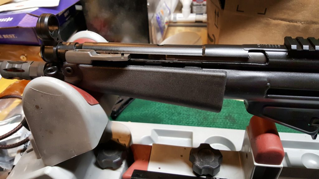
Now, in terms of the handguard, I thought I was going to use the original PTR model you see in the photos above.  It’s a little small left-to right in my hands so I actually wound up changing to a US made wide tropical forearm.  It’s a tad looser than I would care for and will post updates about that later.  I may stick with the existing wide tropical unit or move to a DTAC like I have on my POF-5.

12/17/18 Update:  I’ve now tried three or four models of MP5 handguard and they all wiggle.  I’m either going back to the PTR unit or a DTAC.  The DTAC handguard on my POF-5 has been solid as a rock.

Next up is the optic.


If you find this post useful, please share the link on Facebook, with your friends, etc. Your support is much appreciated and if you have any feedback, please email me at in**@ro*********.com. Please note that for links to other websites, I may be paid via an affiliate program such as Avantlink, Impact, Amazon and eBay.


The PTR PDWR – A Compact .308 Powerhouse

As you know, I really like AK firearms but I also like firearms based on the HK roller lock design.  Maybe 3-4 years ago I owned a PTR-KMF4R and it was very accurate and I also learned a lot in terms of maintenance, tuning, etc.  Of course, I had to mess with it and add a PRS stock, new trigger, and scope but it really was very accurate.  As my interests changed, that rifle was sold to fund other projects but I was impressed.

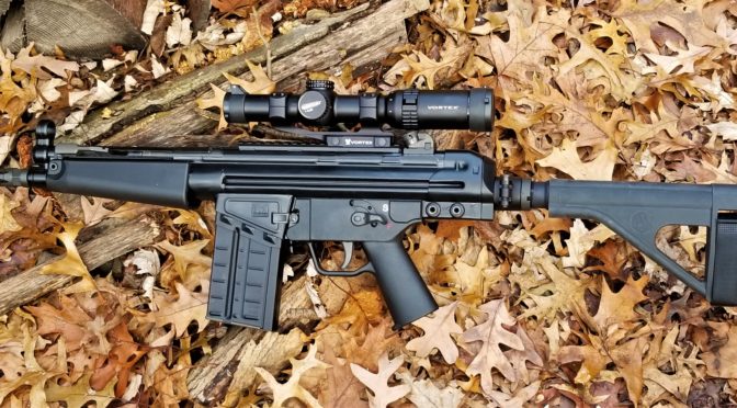
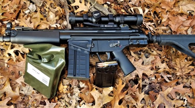
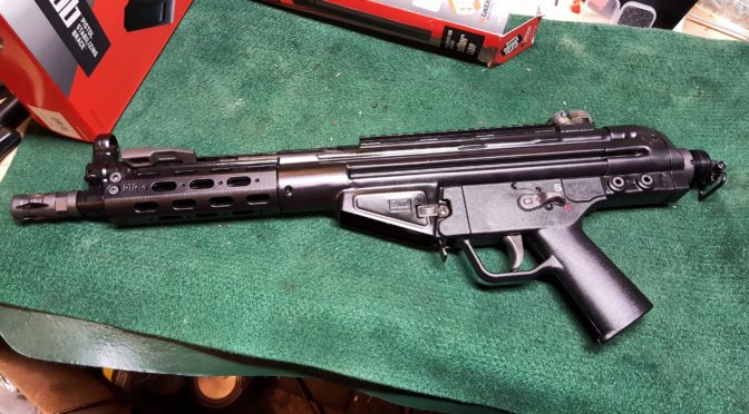
With the reversal of the ATF position on arm braces, I again found myself looking at heavy big pistols that needed braces.  I really like the maneuverability of these weapons.  While looking at options for my next project, I ran across the PTR-105, also known as the “PDWR“.  This thing’s specs rock and I figured out quickly this was my next project.

  • 8.5″ heavy bull barrel with a 5/8×24 thread and 1/10 twist
  • 23.5″ overall length
  • 8.1 pounds empty
  • Milled aluminum handguard that uses proprietary removable rails.  Note, the PDWR actually uses MP5 handguards so you have a ton of options if you want to try different models.
  • It has both button and paddle mag releases
  • The trigger is a lawyer friendly 9-10 pounds
  • 7.5″ welded top rail for optics, which means no additional optic rail is needed as you typically do with non-PTR firearms.
  • It has a swivel cap on the end that is actually a short tube that is the same diameter and pitch as an M4 buffer tube – which means putting on a buffer tube for a brace would be easy plus not come loose.

To this, I should add that you are basically looking at a cut down semi-automatic HK G3/91.  This means you have tons and tons of options for magazines and parts not to mention know how.  I buy my HK-related parts from either HKParts.net or RobertRTG.

You can avail of the various books and manuals out there such as the  HK G3 Armorer’s Manual or either of these operating manuals – an HK91 Scanned Copy or this HK G3 Green Scanned Copy

Also, for those of you unfamiliar with PTR – they have been around for a while now.  They are currently made in Aynor, South Carolina with their original tooling and designs coming from an HK G3 licensed factory in Portugal that they bought in 2003.  This helped them really get started and they have been refining their products ever since.

So, I did some shopping around and ran into Kelley Enterprises via Gunbroker.  They had great reviews there so I also visited their website and met Chuck, the owner.

Chuck is one of those guys who really knows guns, likes his job and likes to talk with folks.  I called him once to talk about MP5 clones and had a great experience with that (which is a blog series for another time) and then when I wanted to find out about this PDWR, he gave me a great price.

Folks, how often do you run into somebody who does exactly what he says, follows up and even sends texts with all the tracking info?  I have nothing but good things to say about Chuck and have now ordered two roller locks from him (this PDWR and a POF-5). You can either visit his website, email or call him at  (305) 923-6560.

Chuck shipped the rifle to my FFL – Scott Igert of Michigan Gun Exchange.  Another man of integrity and deep knowledge that I profoundly respect and recommend to anyone who is looking for an FFL in the Southwest Michigan or Northwest Indiana area or is considering buying one of the many unique firearms that passes through his shop in Benton Harbor, MI.
So, I ordered early in the week, Scott had it by Friday and I was there on Sunday to pick it up.  The two first things I noticed were the weight and the big magazine for holding the .308 (7.62×51) rounds.

I’ll tell you what I did to the pistol in the next post but I will say this – it ran like a top.  Not one single problem after almost 200 rounds but that is a story for another day.


If you find this post useful, please share the link on Facebook, with your friends, etc. Your support is much appreciated and if you have any feedback, please email me at in**@ro*********.com. Please note that for links to other websites, I may be paid via an affiliate program such as Avantlink, Impact, Amazon and eBay.


How to Remove Old Cosmoline and Grease or Even Free Up Rusty Parts The Easy Way

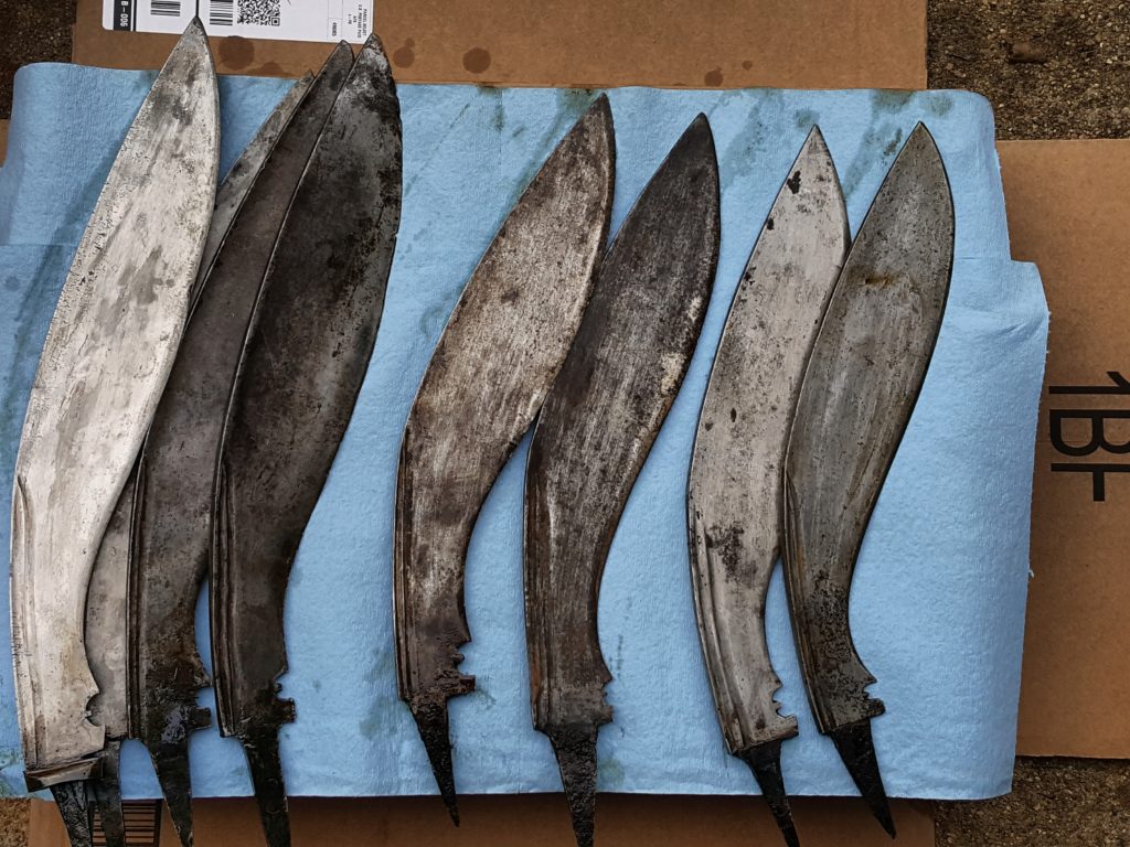
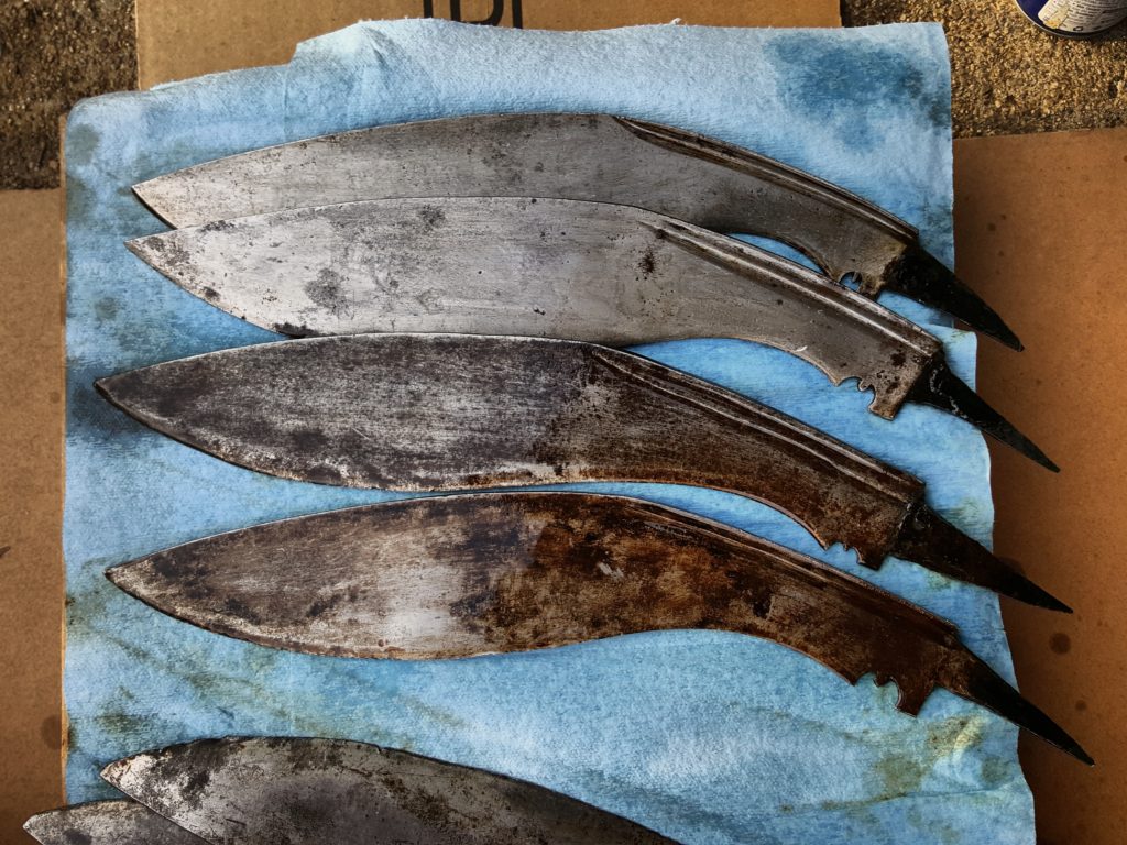
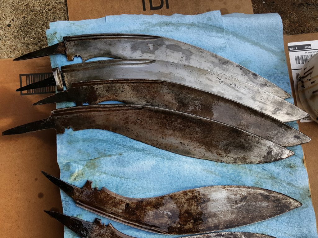
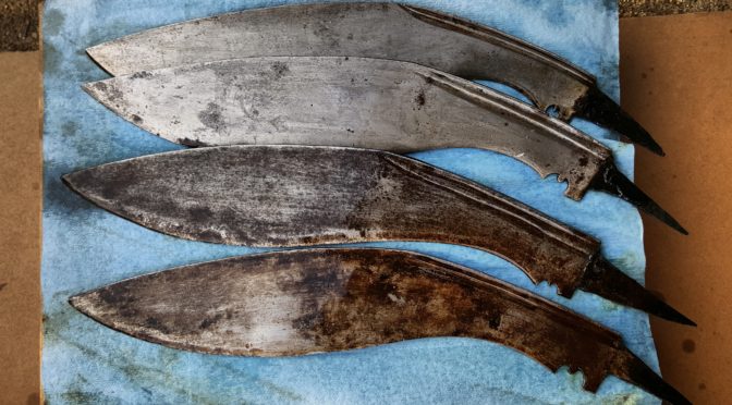
We’ve all had parts come in with really dried out preservative on it such as grease or cosmoline.  I bought some 100 year old khukuri blades that were coated in dried out grease and realized this was a great time to take some photos.  There’s a way to get all this crud off very easily – most will practically wipe off!
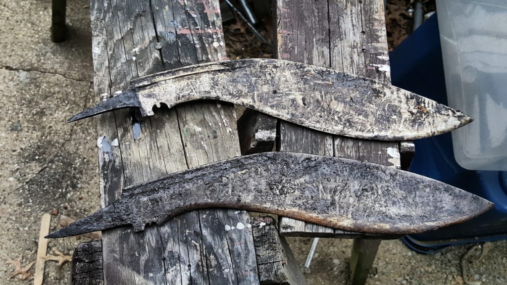
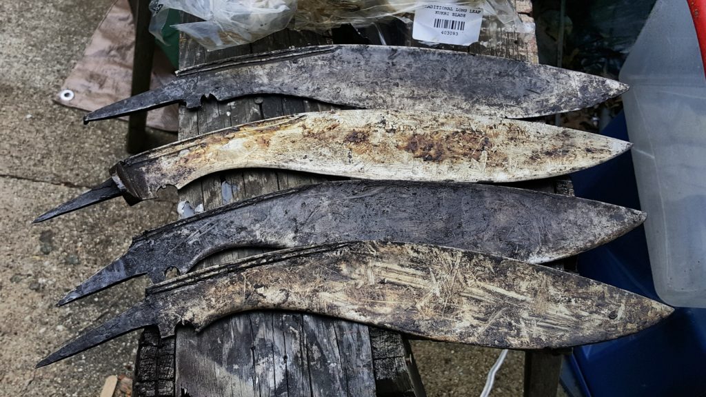
I learned the following trick years ago after a friend was worried I would blow myself up using gas, brake cleaner, etc.  In hindsight I must admit it was risky but I rationalized it because I needed to get the parts clean – this is not only effective but also way safer.

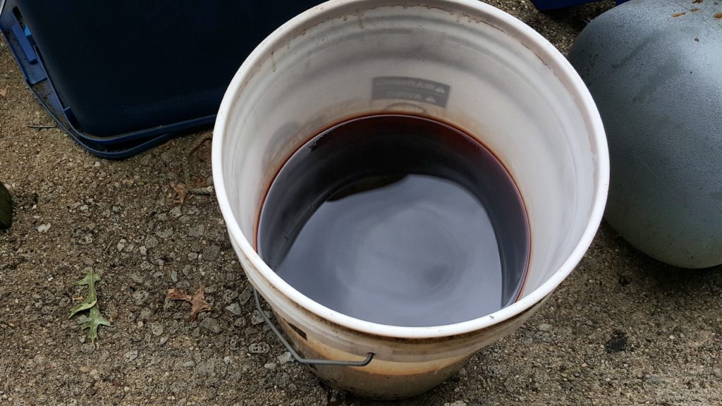
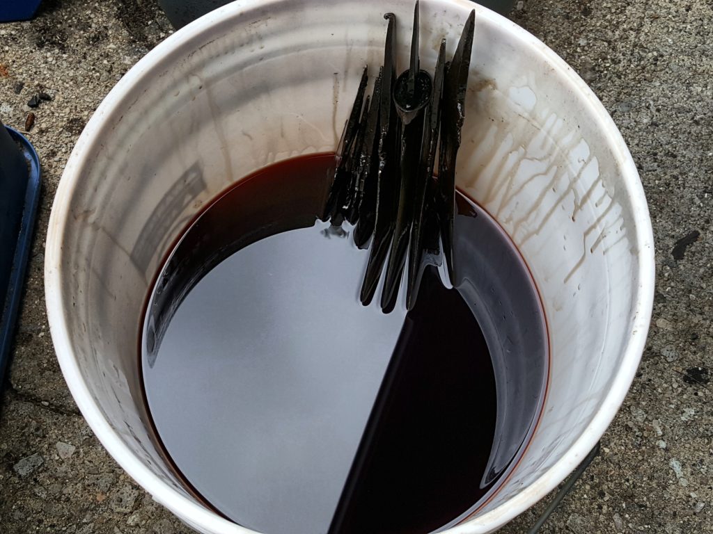
Take a 5 gallon pail with a sealable lid on it.  In the photos you see a basic Ace Hardware plastic bucket with it’s lid that has a waterproof gasket.

I first learned about this years ago for firearms and it is a cleaner known as Ed’s Red and I’ve used it ever since.  The formula was developed and shared by a gentleman named “Ed Harris” and it works great for dissolving grease, cosmoline and even penetrating rusty parts.

The basic formula is:

  • 1 part Dexron III or better
  • 1 part deodorized kerosene
  • 1 part mineral spirits
  • 1 part acetone

I use it over and over, which is why I recommended the lid.  I’ve been using this bucket for probably 3-5 years now.  If it gets really gross or seems to stop working then I will change it but it’s fine so far.

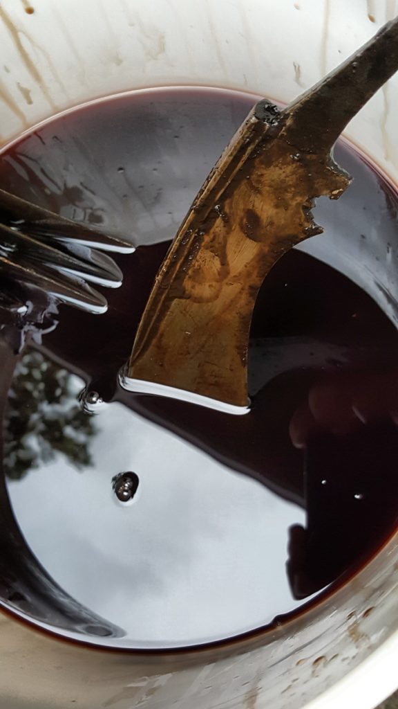
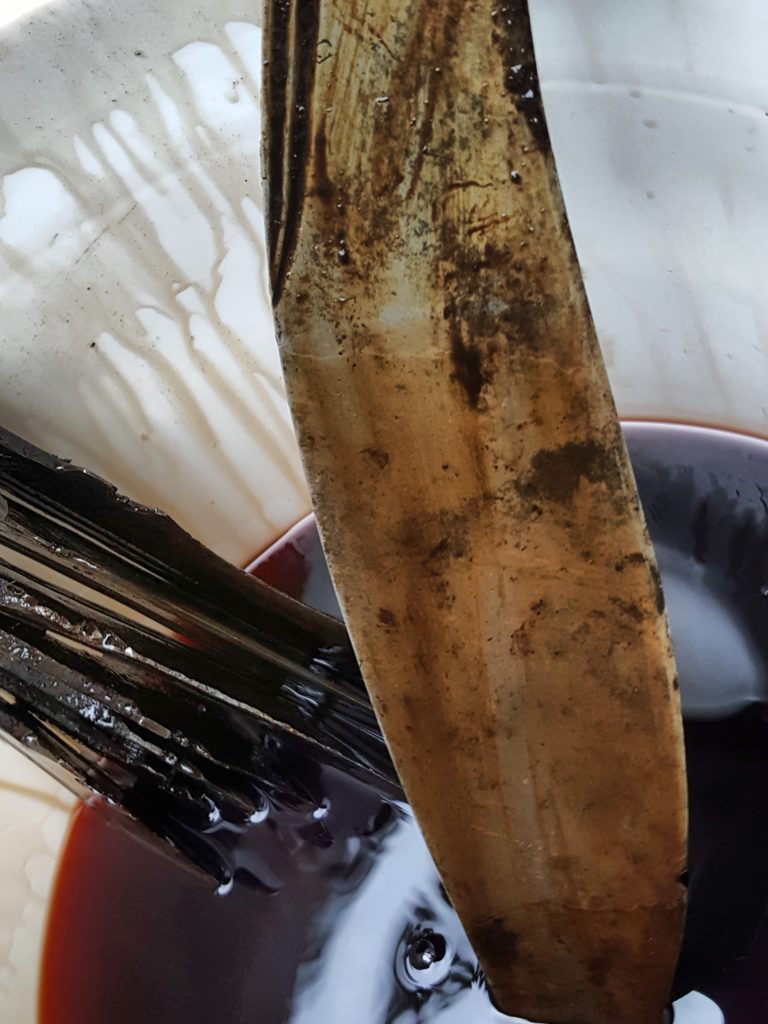
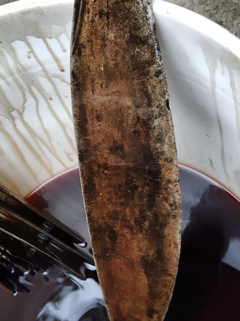
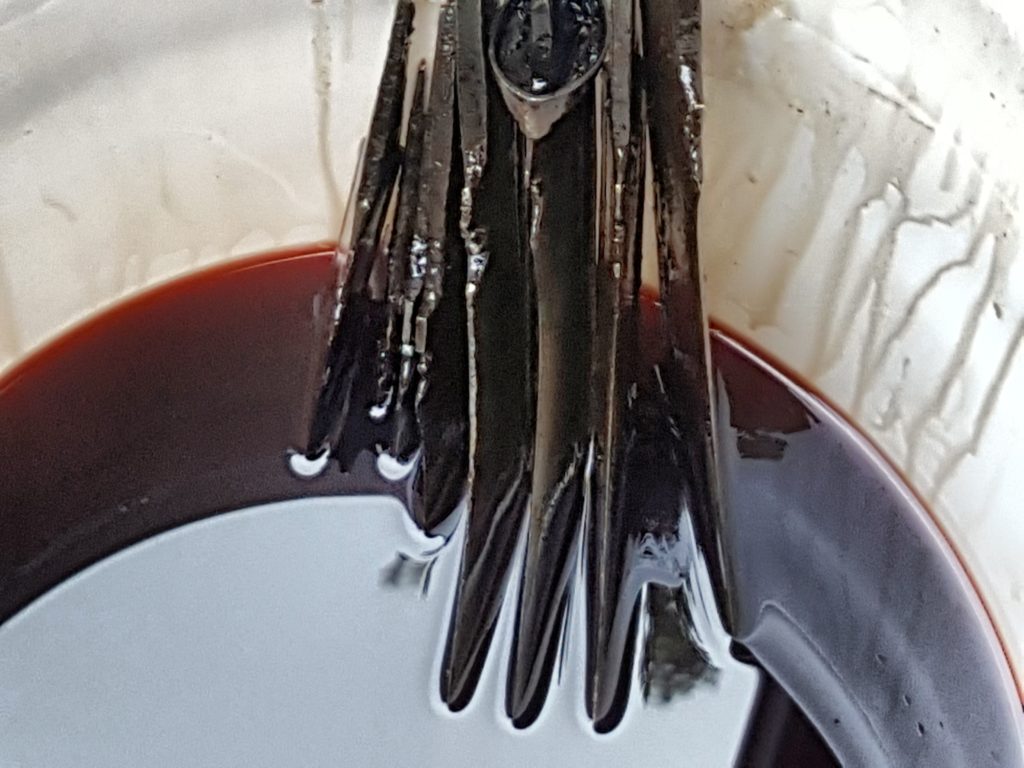
So, I set the blades in the ATF and liberally coated the sides and let it sit.  I periodically would reverse the blades so they could be immersed.  If they were smaller parts, I’d drop them in there and let them sit for a few days.

What I wold so each time when I turned them was to rub the blades down and try and get the softened/dissolved grease off.  A lot of it would wipe right off with no scrubbing.

So here they are a couple of days later simply wiped down.  I left a thin film of ATF on them to reduce the odds of rust but all the old dried grease is gone.

When I am done, I put the lid back on and move the pail out of the way.  I do keep wet parts out of the cleaner as I don’t want to contaminate it with water but other than that, I’ve soaked all kinds of greasy, oily, rusty, dirty parts in this.  The crud settles to the bottom of the pail over time.  I’ve learned that if I stir it up there is a lot of debris.  If it gets too bad, it will be time for a new batch.

I mentioned it in passing but this is also great for penetrating rusty parts so you can take them apart.  I can’t begin to guess what all I have soaked in this bucket over the years but it sure includes gun parts, blades, rusty car parts, etc.  It’s a huge time saver and I hope it helps you out as well.

P.S.  If you want to read more on Ed’s formula, click here for his original article that is in the public domain.


If you find this post useful, please share the link on Facebook, with your friends, etc. Your support is much appreciated and if you have any feedback, please email me at in**@ro*********.com. Please note that for links to other websites, I may be paid via an affiliate program such as Avantlink, Impact, Amazon and eBay.


Yes, 922r Does Apply to Short Barreled Rifles (SBRs)

Please note that I am not an attorney and this does not constitute legal advice.

The topic of 922r compliance and parts counts came up the other day as whether it applies to Short Barreled Rifles (SBR). In reading the conflicting ATF documentation, the last guidance given in technical branch letters from 2009 and 2010, the ATF does say it applies.  I put it this was as you should look at the trend over time which does seem to point towards 922r being applicable.

I am a very conservative guy and always try to stay on the safe side of legal issues so I would recommend ensuring your SBR is compliant with the 922r parts count requirements.  If you do this then you do not need to worry about it and I am sure there are folks who would disagree with me.

Here is the 2009 letter:

Here is the three page 2010 letter:

Again, please let me stress that I am not an attorney.  If you have any questions on this, I would recommend doing your own research and/or retaining legal counsel.


If you find this post useful, please share the link on Facebook, with your friends, etc. Your support is much appreciated and if you have any feedback, please email me at in**@ro*********.com. Please note that for links to other websites, I may be paid via an affiliate program such as Avantlink, Impact, Amazon and eBay.


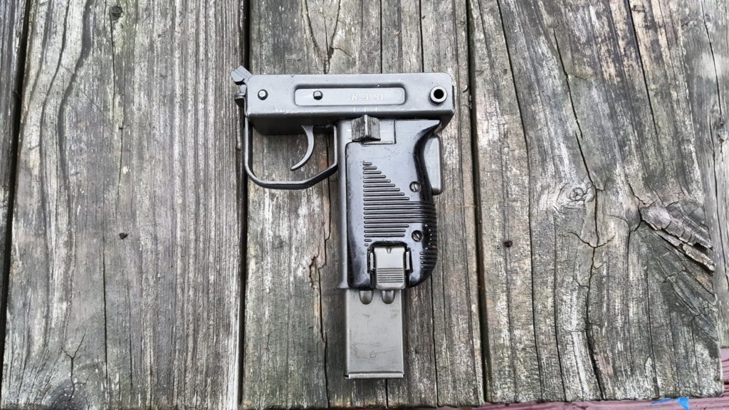
What do the Hebrew Characters on the IDF Uzi Grip Frame Mean?

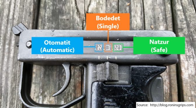
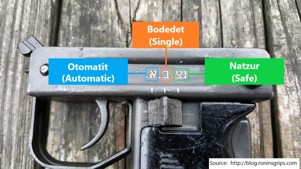
When the Israeli Defense Force (IDF) adopted the Uzi, they had the selector markings written in Hebrew script.  For those of us that can’t read Hebrew, I did some digging as to the translation:

As you can see labelled in the above photo, we have each position marked with the Hebrew term in its romanized form as well as the English translation.

  • Left position:  Otomatit is fully automatic
  • Center position:  Bodedet is single fire / semi-automatic
  • Right position:  Natzur is safe

I hope this helps you out!


If you find this post useful, please share the link on Facebook, with your friends, etc. Your support is much appreciated and if you have any feedback, please email me at in**@ro*********.com. Please note that for links to other websites, I may be paid via an affiliate program such as Avantlink, Impact, Amazon and eBay.


Uzi Part 7 of 7: The Bolt and Final Assembly of the Semi-Auto Uzi Carbine

So the semi-auto 9mm Uzi carbine build has the Molyresin applied and is ready to go together.  The following is an overview of the final assembly steps:

1]  Install the grip frame assembly.  Insert the tip first and swing the back up into position.  Install the grip frame takedown pin.  If the assembly will not go into position you may need to remove the bolt safety.  The McKay receiver and bolt do not use that part.  If you have questions about the grip assembly and preparing it for semi-auto use, click here.

2] Install the stock bracket with its 1/4″ screw and then the stock itself with its three screws taking care to use the correct bit on the slotted screws.  Make sure the bolt doesn’t stick in too far.  If you have questions about converting the quick detach stock to be permanently attached, click here.

3] The handguards are installed with the two screws.  I did my initial build with the beat up originals but then purchased a new set from US Barrel Shroud that isn’t shown in these photos.

4] I installed the barrel nut catch and spring plus the front sight.  Slide the catch far enough back that it hooks the receiver and does not come back out.

5] I then installed the rear top cover catch and rear sight.  The trick here is to push down on the flip sight while pushing the screw through so the threads can engage on the other side.  The little tiny but just locks it in place – the receiver itself is threaded also. Note, I did have an issue with either the thread on the bolt or the receiver.  I could not get the rear sight screw to enter on the opposite threaded side.  After playing with it for a few minutes it dawned on me that either the screw or the threading in the “ear” of the receiver could be messed up so I installed the screw from the opposite direction just to chase the threads real quick and that solved whatever the problem was because when I then tried to insert it the correct way, the screw went right in.

6] Rather than mess with rivets, I tapped the front sling for a #10-28 screw.  I sanded down the head of the screw to avoid interference with the bolt and then applied medium Loctite to the thread when i installed it.  If you need to remove more of the screw head later it can be readily reached with a Dremel and a flap sander or whatever bit you wish.

7]  The 16″ semi-auto barrel slide right into the front trunnion and into the ring of the semi-auto feed ramp.  Rather than use the barrel nut, I opted for a very cool two piece barrel shroud from Title II Arms.  It is solid aluminum and exceptionally well made.  Note, I show a light on a rail adapter on the bayonet lug.  It looks cool but I actually removed it as my hand’s natural hold runs right into it.  It’s not a reflection of the CAA rail but it’s just not for me.  With it gone, my hand can go right out to the end of the handguard and is much more comfortable.

8]  Next it was time to sort out the striker fired bolt system.  This raises a critical legal point –the weapon must fire from a closed bolt.  This means you can’t use the original open bolt.  After some digging, I decided to use the McKay closed semi-auto bolt system for my build.  Now McKay components are popular and they were out of stock on the complete bolt assembly but Robert RTG had it in stock so I bought it and other parts from them.  As of my writing this, for example, McKay has their receivers in stock, bolt assembly but not the barrel so you can check between both firms plus McKay says they sell to Sarco and Apex.

9]  I had to do some reading to figure out how the bolt went together as I had never seen anything quite like it before.  The best write-up I could find that really helped me is right here.  In a nut shell, take your original bolt, push out the extractor retaining pin and then push the extractor straight out the front of the bolt.  From the rear, the extractor looks like a screw due to the slotted head but it is not.  The slot is there to make it easy for you to rotate the extractor into position.  Insert the extractor into the new semi-auto bolt.  You will notice that with your semi-auto bolt a small blocking latch and pin are included just like you would see in the Uzi Pro Pistol – indeed, the whole bolt assembly is very similar to the Uzi Pro Pistol if you look it up.  The little spring and the latch are inserted into the bolt and held in place by the extractor pin in the semi-auto bolt.

Ok – this next photo shows a problem that I didn’t find out until the first trip to the range.  At the lower right of bolt is a pin that holds the extractor in place plus you can see a tab sticking down – that is the locking latch.  Now look at the striker.  You can’t see clearly but it is a half moon shape and I have it installed backward.  The notch, or part of the striker’s base that is missing should be what goes against the bolt blocking latch.  If you get it backward the weapon will not fire and you’ll notice the striker base getting beaten up by the latch.

Here’s the blocking latch – see how the bottom part stocks out?  That is what will need to clear the notch when it is depressed during normal operation.

Here’s what it should look like – note how the striker bar has a smooth side and one with a relieved/depressed surface?  The notched striker base goes towards the smooth portion:

Here you can see the base that is towards the relieved/depressed area plus you can see the blocking latch will let the striker come forward only if the latch is depressed.  The chewed up area on the striker is from my mistaken assembly and a ton of testing trying to figure out what I did wrong.

Here’s another angle.  The striker can only travel forward if that blocking latch is depressed – in the photo, the latch would be pushed down out of the way.  In the Uzi with the bolt oriented the normal way, we would say the latch is being pressed upward.

Last pic:

10]  If you look at the above photo, the striker system.  The lower L-shaped bracket is the “Striker Guide”.  Thestriker spring base and the striker are held in place by a roll pin.  The return spring slides over the striker spring base as shown above.

11]  Take the guide rod and spring from the kit and snip the fiber square board off the end.  I used diagonal cutters and when I made my first cut the little board fell right off.

12]  You then insert the recoil spring into the bolt and rotate the firing pin base while inserting the assembly into the bolt.  The white is Tetra Firearm Grease.  If it slides, grease it.  If it rotates, oil it.  You want this system to be well lubed to help it wear in.

13]  Here is the whole bolt assembly with the recoil buffer at the end.  Now this assebly is slid into the Uzi buffer end first.  It takes some maneuvering to the recoil block into the rear and then the bolt nestles down.

14] The top cover is then installed.  I used a 120 grit flap sander bit to slightly bevel my top cover to the catch can close and the top is really tight.  The top black cover has the bevel in the photo below – it doesn’t take much.  If you have any questions about what needs to be done to prepare the top cover for semi-auto use, click here.

14.1 – Added 7/2/18:  I found out that you really need to fit the top cover.  If you take a feeler gauge, you should be able to insert a 0.005 gauge between the bolt body and the top cover at the ejection port and meet little to no resistance.  However, if you insert a 0.015 gauge, you should feel some resistance – not a complete stop but firm resistance.  At 0.005, the gap is too small and you risk the bolt body binding and not travelling fast enough or far enough resulting in ejection and feed problems.  The cover is very easy to adjust.  I did a more detailed blog about testing and adjusting the cover – click here.

15] Now function test it to be safe.  Do this with the weapon unloaded!!

  • Try to move the selector switch to Full Auto, which is all the way forward.  It must not be able to move past semi-auto.  If it does slide to the forward full auto position, you must fix it.  If you haven’t done so, you need to install or fix your blocking tab that should be welded in the grip frame – click here for details.  If you welded in a blocking plate, it may be too thin or too short.  Regardless, you must figure out what is going on and fix it immediately.  The ATF says the selector must not move into the full auto position.
  • Move the selector to semi-auto (the middle position), hold the grip safety, cock the weapon and squeeze trigger – you should here it dry fire with a real solid clunk sound. Life is good.  If there is a soft click, the striker system did not cock – check your sear to make sure it is protruding into the receiver.
  • Move the selector to semi-auto (the middle position), DO NOT hold the grip safety, cock the weapon and squeeze trigger – the weapon should not fire.  The Uzi should only be able to fire if on semi-auto and the grip safety is held.  Check your pins and that the grip safety bar is sliding properly.
  • Move the selector to safe (all the way to the rear), hold the grip safety, cock the weapon and squeeze the trigger – the trigger should be blocked and nothing should happen.  Turn the safety off and the weapon should fire.  If it does not, check the pins and the selector bar can move into position properly and block the trigger.
  • Last, move the selector to semi-auto, hold the grip safety, squeeze the trigger (do not release it) and cock the weapon while holding the trigger in.  We want to ensure the disconnector grabs the striker assembly.  Now, release the trigger and squeeze it like normal.  You should here it dry fire with a loud clunk sound and that is what you want.  A light click is just the trigger and disconnector moving around and means the striker went back into battery vs. being retained.  Something is off with the geometry – something is bent, you forgot to secure the grip frame with the takedown pin, etc.

If your Uzi passes the function tests, then proceed to test firing.  I’d recommend securing the carbine in a stand and test firing with a string vs. holding the weapon.  Also, only load one round in the magazine at a time and inspecting the carbine, especially the barrel, to make sure the first round fires and the case is ejected.  Look for dings or tears in the case.  Make sure the bullet didn’t get stuck in the barrel.  If things are looking good, put two rounds in the magazine and test the overall cycling of the weapon.  Again, check the case for any big gouges, scrapes, etc.  When you are satisfied that the weapon is functioning correctly, then and only then try more and more rounds of ammo.  I would go from one, to two, to three to five and to 10 before I tried a full clip.  You do not want to have an uncontrolled full auto dump happen so carefully test the Uzi.

I had a lot of fun building mine.  I added a Vortex Venom red dot that I really like so far plus an original Uzi green sling.  Here are some photos and as mentioned the light and rail are off the weapon at this point.

I hope this helps and if you have any suggestions, please let me know.

7/2/2018 Update – I did get rid of the light/laser on the front.  It was in the way of my hand.  I also have some recommendations to double check in case your Uzi has any problems firing – click here.


If you find this post useful, please share the link on Facebook, with your friends, etc. Your support is much appreciated and if you have any feedback, please email me at in**@ro*********.com. Please note that for links to other websites, I may be paid via an affiliate program such as Avantlink, Impact, Amazon and eBay.