The AK-47 rifle and it’s “banana” 30 round magazine are classics of rugged functional design. While I’ve posted many videos and how-to articles relating to various rifle and pistol variants, I’ve not really covered the steel magazines at all.
I was surfing around and found Matra Group located in Bosnia-Herzegovina. In 2015 this small manufacturer produced a video showcasing their small facility that makes a variety of steel magazines for AK-47, AK-74 and even Lee-Enfield rifles. The Lee-Enfield may be due to those rifles being supplied to the Yugoslav Partisans in WWII to fight th axis armies.
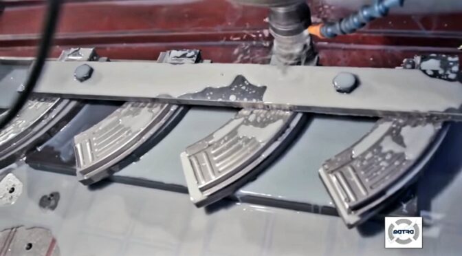
In the video, they show employees starting with sheet metal and stepping through various steps including stamping, machining and spot welding. For the most part, you will see a very labor intensie process using older general purpose machines. If you like videos that showcase how something is made in and old-school fashion, you will find this very interesting.
Here they are cutting the initial sheet down into usable blanks.Making the front piecee that will lock onto the front trunnion.Spot welding the two body halves together.Gettingg ready for final assembly.
Please note that all images were extracted from the video and are the property of their respective owner.
If you find this post useful, please share the link on Facebook, with your friends, etc. Your support is much appreciated and if you have any feedback, please email me at in**@*********ps.com. Please note that for links to other websites, I may be paid via an affiliate program such as Avantlink, Impact, Amazon and eBay.
Many folks have heard of the US Navy’s Sea Air and Land (SEAL) teams. The SEALs have been in a ton of movies and books but they are supported by another critical special warfare group – the Special Warfare Combatant-craft Crewman (SWCC). These are the teams that man the small boats that deliver and pick up the SEALs.
I have a lot of respect for the SWCC crews and get a real kick out of their boats – wow. These things are packing some serious firepower.
So, I ran across this cool motivational video this morning and thought I would share it:
Please note that all images are extracted from the video and remain the property of their respective owner(s).
If you find this post useful, please share the link on Facebook, with your friends, etc. Your support is much appreciated and if you have any feedback, please email me at in**@*********ps.com. Please note that for links to other websites, I may be paid via an affiliate program such as Avantlink, Impact, Amazon and eBay.
Military Division makes some kick ass motivational videos of different special forces groups. They released this video entitled “Wolves || Ukrainian SOF” on December 6, 2019. It has some great videos and a wicked track.
What caught my eye is a number of shots of the Ukrainian Malyuk Bullpup Assault Rifle. I’m not sure what caliber they are running in the video but you can get it in 5.45×39, 7.62×39 and 5.56×45.
You can see a combination of AKs and also the Malyuk bull[pup.Another view of two MalyuksPretty cool shot of a modern AK – note the EOTech and magnifier.Another Malyuk shotThis is another cool rifle to show itself. It’s an AR pattern sniper rifle – the 7.62×51 UR-10 – with a can. It was in trials in for a number of years and announced in February 2018.
The Really Cool Video
I hope you enjoyed it!
Please note that all photos were extracted from the video and remain the property of their respective owner(s).
If you find this post useful, please share the link on Facebook, with your friends, etc. Your support is much appreciated and if you have any feedback, please email me at in**@*********ps.com. Please note that for links to other websites, I may be paid via an affiliate program such as Avantlink, Impact, Amazon and eBay.
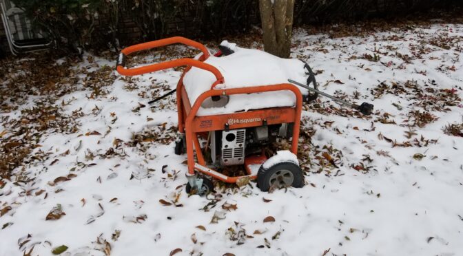
Whether you call it them pressure washers or power washers, these are darned handy machines to have around. For portability, we use models with a gasoline engine and are on our second one. The first lasted for a few years until one wither the water in the pump turned to ice and finally cracked the housing. As they say “and that was that”. I thought about just buying a pump but for a little bit more we bought a whole new unit. My friends also cautioned me to always winterize the unit to make it last through Michigan winters. That was 6-8 years ago and I have learned a few tips to share.
By the way, the photo above really is of our pressure washer. I don’t have space to store it indoors so I really do need to Winterize it. Regardless of the brand you buy, there are three things I would tell you to do.
Drain the gas and/or use a mix with Stabil
Assuming you have a gasoline pressure washer, you might want to drain the gas from the tank and run the unit until it stalls. There are two reasons for this – gas can spoil if left untreated and also, when it evaporates out of the carb it will leave a gummy residue that may need to be cleaned out. In my case, my washer only sits idle a few months so I don’t always drain it. I’ve not had a problem so far. I always drain my chain saws because they may sit an unpredictable amount of time.
The second recommentation that you can do along with the first is to always add Stabil, a gasoline conditioner, that keeps it from breaking down for at least 12 months. I always add it to all of my gas cans when I fill them.
Blow out the system and disconnect the gun/wand and hose
What did in my first pressure washer was not draining the water out of the pump. I made a small air fitting by taking an old piece of hose and a 1/4″ air fitting that I can screw into the pressure washer and blow all of the water out of the pump, lines and wand. It works great.
I just use junk hose to make the adapter. You just need a male hose fitting on one end and a way to connect your compressor on the other.
If you really want, you can buy pre-made winterizer fittings for $12-20. The above fittings were all made with old stuff I had laying around.
Drain The Soap Tank
Don’t forget to drain the soap tank also. You don’t want it to freeze and crack anything. I did forget this one year and had to rebuild the fitting that cracked with epoxy.
Don’t forget to drain the soap from the plastic soap tank.
Add a Winterizing fluid
I then use an aerosol based pump winterizer. It can blow the water out by itself technically but I’m paranoid. I use my compressor to blow out everything and then I disconnect the air lines and wand/gun. I then connect the Briggs & Stratton 6151 Pressure Washer Pump Saver Anti-Freeze and Lubricant to further protect against freezing and to lubricate the pump and prevent the O-rings and seals from drying out. This works great for me and one can will last me 2-3 years at least.
This is what I use and have never had a problem.All you do is connect the hose assembly to the hose inlet and push the trigger. The foam will come out pretty quick – it doesn’t take a lot. Note, stand to the side or you will wear the foam. I kid you not that it took me two years of wearing foam until I remembered to stand to the side when filling the unit with foam. Also, remove the hose and wand/gun before doing this or you will use a lot of material to purge them also. You can blow them out or even hang and drain them vs. using this stuff unnecessarily.
Now a ton of reputable companies sell some form of pump protector / winterizer. I suspect one or two companies actually make it and then applies different labels – Generac, Briggs & Straton, Stabil, etc. Just go with a name brand and I bet you will be fine.
Summary
I hope this helps you out. My current pump is still going strong even though it is out in the winter weather every year. The paint is fading but it is mechanically solid.
If you find this post useful, please share the link on Facebook, with your friends, etc. Your support is much appreciated and if you have any feedback, please email me at in**@*********ps.com. Please note that for links to other websites, I may be paid via an affiliate program such as Avantlink, Impact, Amazon and eBay.
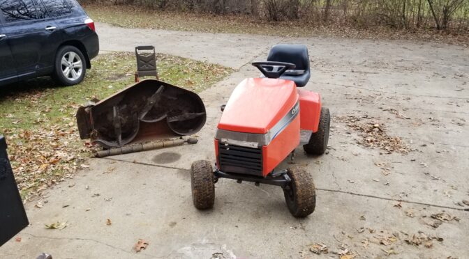
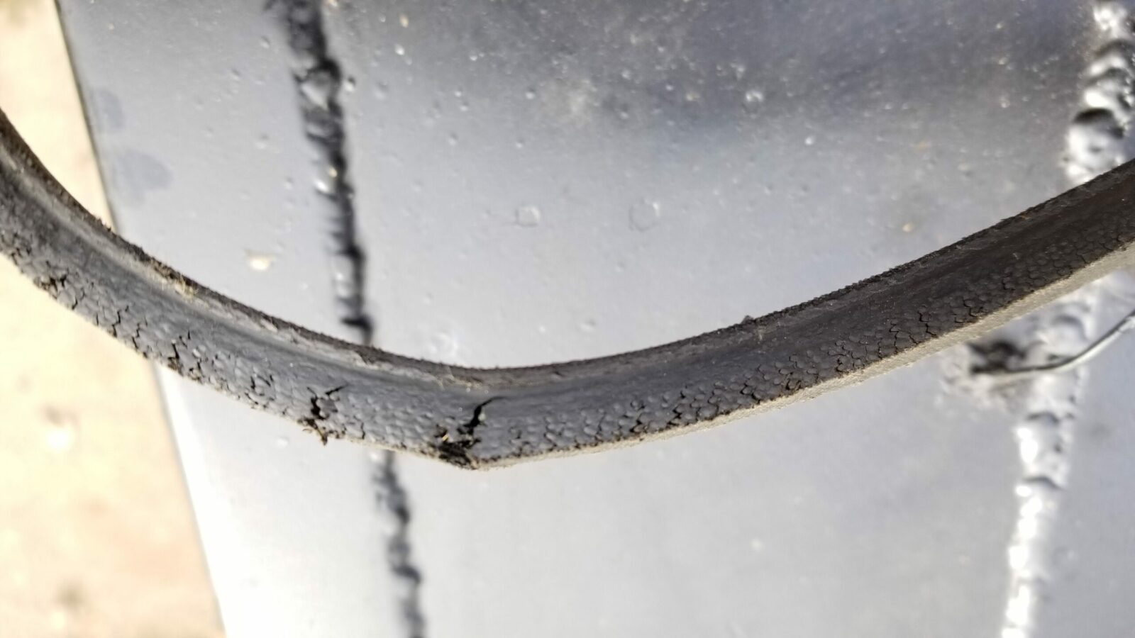
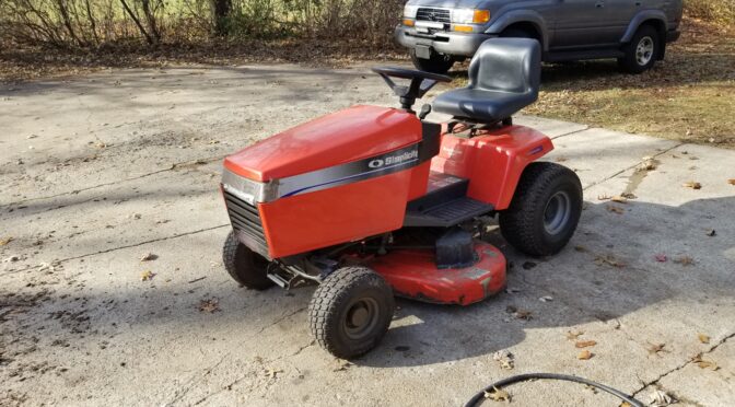
This fall we had a ton of leaves to mulch as usual. This means every week I mow our acre and a half for about two hours at a time. Long ago, I replaced the OEM Simplicity blades with Oregon Gator blades in the tractor’s 44″ mowing deck to help with this. At any rate, I pushed on the parking brake and all of a sudden heard a weird rattling sound so I turned the tractor off expecting to see a branch stuck underneath – no such luck. I started feeling and looking around and the drive belt felt loose and the idler assembly was as far as it could go. I looked closer and could see the cracks in the 21 year old original drive belt. Argh …. it needed a new drive belt and I really didn’t have the time but what are you going to do?
Finding the Belt
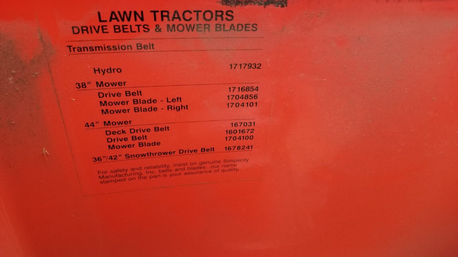
Simplicity did me a favor by having a decal under the hood that identified the drive belt part number along with a few other belts:
The top one is the drive belt – the 1717932 part number.
The correct drive belt part number for the tractor is the 1717932. If you look that part number up, it is an 84″ belt with a 4L profile. “4L” means that the top of the V=belt is a 1/2″ wide and from top to bottom, it is 5/16″ tall. The “L” means the belt is for light industrial or lawn & garden use.
Now, one could argue the original belt lasted 21 years so just get the same thing – either an original Simplicity part of a good 4L-84 belt. I tend to like safety margins and when something is a bear to do, I really just want to do it once and not worry about it again for a long time if ever. I have no idea how long the tractor will last – I’m replacing parts like the ignition switch and starter and even more recently torquing the motor mount screws back down. More concerning is that it smokes just a tad after it starts (wearing valve stem seals I bet) and has a slow oil drip (seals). At some point it will die on me but I do hope it is a long way down the road plus a friend pointed out I like tinkering and it gives me something to do – as if I ever have free time anways.
At any rate, let’s get back to the drive belt. All belts deteriorate over time. The question becomes how fast will they break down? There are many factors including the rubbers and fibers used plus the strain placed on the belt. 21 years was really a good run but I wanted to up my game and move to a 4LK belt – the “K” means that that Kevlar fiber is used vs. polyester or whatever.
I did take a bit of a gamble on the D&D PowerDrive belt – it had one good review and one complaint that it was the wrong size. D&D belts get mixed reviews but seem to be more positive than negative so we’ll see. I’ll post updates about how well it lasts because it definitely will be installed correctly.
If you are wondering why I didn’t get a Gates or a Dayton – I tried to go with an easy purchase experience. Hopefully it sorts out in the long run and time will tell.
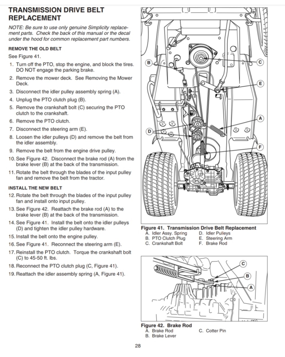
How to Install the Belt
The installation went pretty well with two notable exceptions that I will cover shortly. I did some digging on the web and found a PDF of what to do that I then converted into a screenshot for you:
My two biggest headaches were unplugging the PTO clutch and then removing the damn cotter pin on the brake rod. For the PTO clutch electric fitting, slide a blade up under the locking tab and then keep working around the block with a small screw driver to try and loosen it up. I suspect that fitting hadn’t been disconnected since the factor and it did not want to come loose. Be careful to pull the fitting apart by focusing your efforts on the plug and the housing – if you pull on the wires, they may pull out. Eventually it did come apart and when I reassembled it, I applied silicone di-electric grease to both seal the connections and ease disassembly in the future.
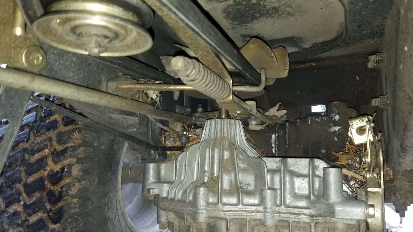
The hardest step was removing the cotter pin (C) that secures the brake rod (A) onto the brake lever (B) in Figure 42 above. It is an absolute pain in the ass to get to and I had to work blind because I could only get one hand back in there. How they made it a pain was that the closed end of the pin was facing towards the inner rear meaning I could not hook it and pull. What I did was to take and hook the flared ends and pulled them relatively straight. I then shoved one jaw of a pair of needlenose pliers into the eye of the pin. To remove the pin, I then rotated the pliers and wound/curled the pin around the jaws until it was out of the hole. Sheeesh. When I reassembled it later, I put the eye facing the front of the tractor so I can grab and pull it way easier. By the way, I did not use a Dremel to cut out the pin because the plastic reservoir for the transmission oil was too close for comfort.
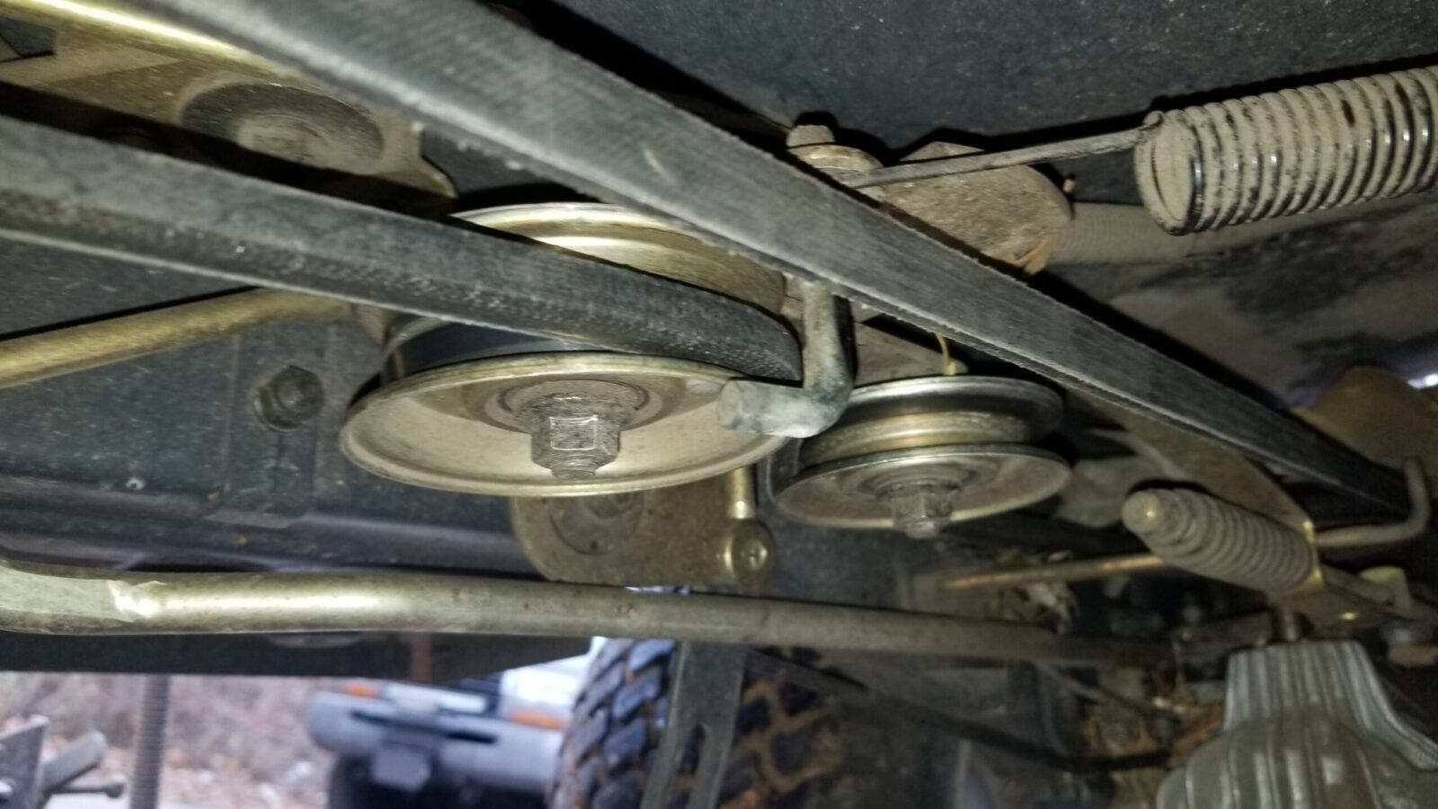
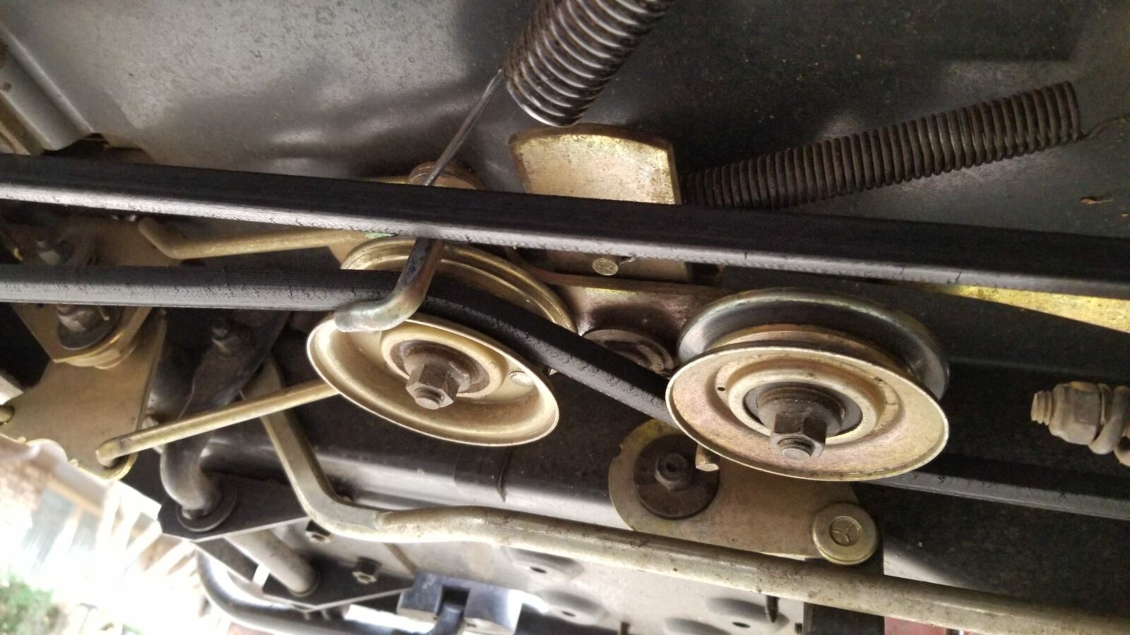
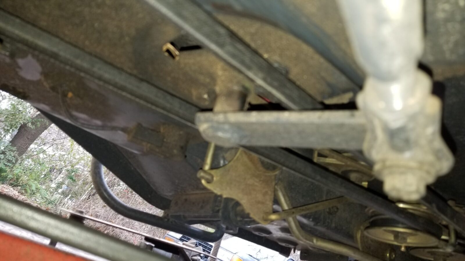
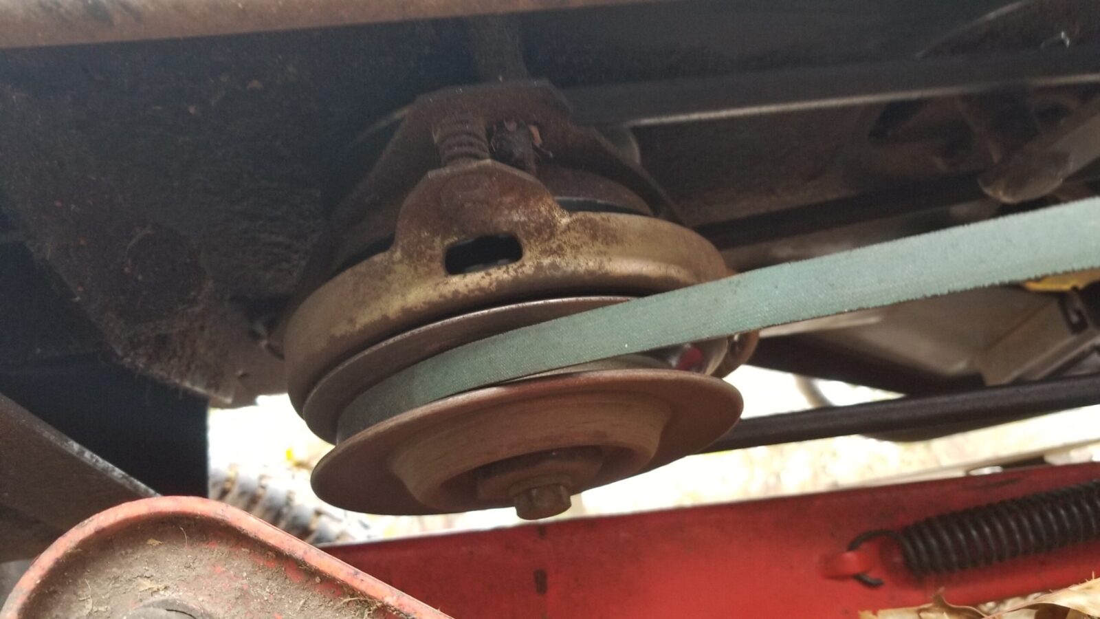
Before you remove the old belt, pay careful attention to the belt and how it passes around the brake assembly, through the idler assembly and around the arm. The illustration above is pretty good but the devil is in the details and the belt must not rub on anything when reassembled. My tip would be to take a ton of digital photos to refer to. In the old days you had to sketch stuff and the photos are way easier.
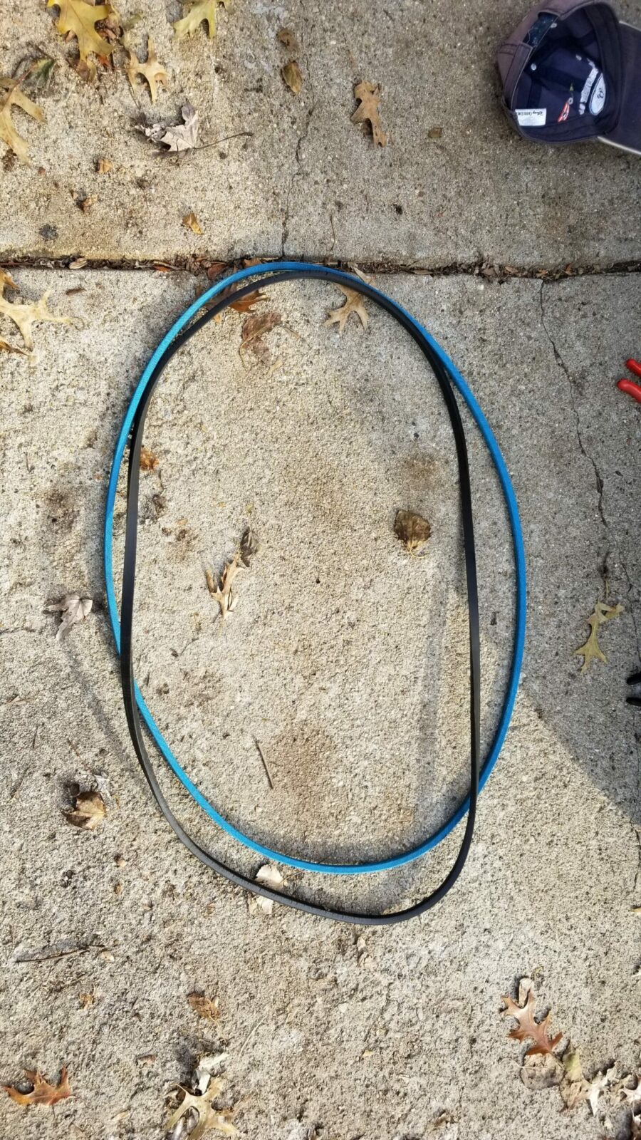
Here’s the original bet relative to the brake assembly.Idler view oneIdler view 2Clearing the steering armThe electric PTO clutchThe original belt was in tough shapeThe new belt was just a tad bit shorter when I stretched them out side by side with my hands. I learned years ago to confirm the belt as best you can before you install it. I double checked the part number on the bag before I even began just to cut my risk. It sucks to have stuff apart or be in a real awkward position and then find out you have the wrong part.
In Conclusion
Kudos to Simplicity for a good illustration and guide. Re-assembly went smoothly and I then mowed/mulched leaves for two hours including some really thick areas so it passed the first trial by fire. Looking up under the tractor, the belt looks solid – no fraying or cracks. We’ll see how it holds up over time and I’ll report back but so far, so good. I hope this helps you out.
If you find this post useful, please share the link on Facebook, with your friends, etc. Your support is much appreciated and if you have any feedback, please email me at in**@*********ps.com. Please note that for links to other websites, I may be paid via an affiliate program such as Avantlink, Impact, Amazon and eBay.
We bought our Simplicty 16HP Broadmor tractor back in 1998 mainly because my dad had a Simplicity that he kept running for almost 30 years. So here are in on 2019 and the tractor is starting to show its age plus the dealership is long gone so a lot of self-service and tinkering happens now.
I was mowing leaves a few weeks back on out acre and a half property when I had to turn the tractor off to pick up branches and move stuff around. I went to start it up and immediately heard thud, thud , thud, thud … so I turned the tractor off. Oh crap … the last time I heard a sound like this a car had bent a rod. I immediately checked the oil and it was almost empty.
Now I was really pissed off at myself. I knew it was burning oil but why had I let it get so low? I thought it had a low oil level protection device to stop it running … Needless to say,I was mad and I knew the fault was all mine. It was the worst possible time also – we simply could not afford to replace the tractor.
So, I filled the oil and figured I would run it until it failed. I had to get the leaves done and that’s just what I did. I ran it for another hour and put the tractor away while feeling like an idiot the whole time.
A week later we had a ton more leaves on the ground so I went to get the tractor out of the shed fully expecting it not to start. Much to my surprise, it did start and I made it half way through the yard when I had to turn it off to eat lunch with my wife.
When I went back out I started it up and it was really clanging away and the tractor was really vibrating but the engine sounded good. I turned the engine off and thought about it. I assumed it was a rod because of the low oil but what if that was not the problem?
The exhaust was tight and not rusted out. The oil level was good. So I started it with the top open and put my hand on the engine to feel for vibrations and the thudding stopped …. Holy Crap???? I took my hand off and it started thudding. Put it on and it stopped. I turned the ignition off and found that I could move the engine on the frame!!
I looked under the frame and one motor mount screw was in the hole but loose. Another was cocked in the hole ready to fall out and the other two werre missing. As luck would have it, I found one screw in the yard. Looking at it jogged my memory of a screw I found a few weeks earlier and couldn’t figure out where it came from. To this day I am not sure if I threw the screw out or tossed it somewhere in my shop – I thinkI threw it out.
So, after almost 21 years, the motor mount screws came loose. It never occured to me to check them. Now, here’s what I want to share with you – the screws are M8 diameter x 1.25 pitch x 30mm long. You can find them at hardware stores, etc. The original bolts also have a washer and lockwasher. I bought the replacement and was good to go.
Say hello to Mr. replacement bolt, washer and lock washer. After torquing things down, the tractor was running smooth again. Duh.
The torque spec is 40 foot pounds and if you want to never deal with them again, put a bit of blue loctite on the screws. Note, I would highly recommend that if the engine is hot, let the engine cool down before torquing on aluminum. I’ve watched threads strip on hot aluminum way too many times and have learned to be patient although a floor fan pointing at the engine will help it cool down a lot faster.
When I started the tractor again after replacing the bolt and torquing down all the bolts it was a huge relief to see and hear the tractor operating normally. I figured it was a good story to share.
Moral of the story – don’t assume and check before you jump to a conclusion. I did make a big assumption based on the sound and freaked myself out before I started the process of elimination that I should have started with. I hope this helps you out.
If you find this post useful, please share the link on Facebook, with your friends, etc. Your support is much appreciated and if you have any feedback, please email me at in**@*********ps.com. Please note that for links to other websites, I may be paid via an affiliate program such as Avantlink, Impact, Amazon and eBay.
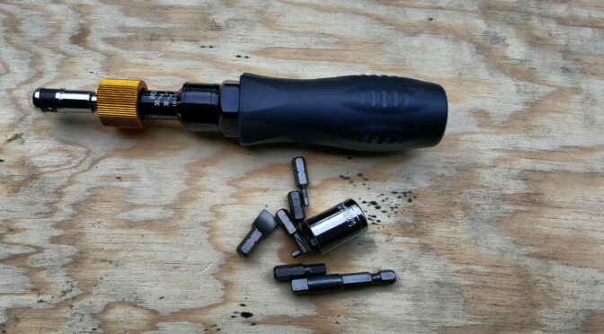
We’ve all been there – you’re working on a project and wondering how much to torque something so either we don’t bother or just take a guess. What I only found out recently was that in 2017, NASA published a really cool guide called “Installation Torque Tables for Noncritical Applications” – with the document ID as NASA/TM—2017-219475.
The document provides the torque specifications for a ton of general purpose fasteners that do not have an exact specification assigned – hence the term non-critical. As you can imagine, they get very specific in critical/risky situations.
At any rate, given the size of the bolt or screw, the thread pitch, the material and the depth, they provide a reference torque specification you can follow for both metric (M6, M8, M10, etc.) and SAE (#8, #10, 1/8, 1/4, 3/8, etc.) fasteners. Note, they provide an assembly torque (which is a 65% load from failure) and 100% torque. I use the assembly torque spec.
They also recommend that the depth of thread engagement be 1.5x the diameter of the fastener. So a 1/4″ (0.25″) fastener should have at least 0.25″ x 1.5 = .375″ (3/8″).
Here’s an example table. This is for fasteners going into 6061-T6 aluminum with a thread depth of 3/16″. If we go down for a 10-32 UNF screw, the assembly torque is 22.2 inch pounds. I’d use that lacking any other detailed information. I could go up to 34.2 inch pounds but I have stripped so many fasteners I don’t risk it. I’m a huge fan of Loctite so I go with that and the assembly spec.
Kudos to the two authors and to NASA for making it available. The PDF is a cool reference document and one I use whenever I can’t find a specific torque value for a given application. All you machinists and engineers – you know way more than me so please let me know if you have other resources you recommend.
If you find this post useful, please share the link on Facebook, with your friends, etc. Your support is much appreciated and if you have any feedback, please email me at in**@*********ps.com. Please note that for links to other websites, I may be paid via an affiliate program such as Avantlink, Impact, Amazon and eBay.
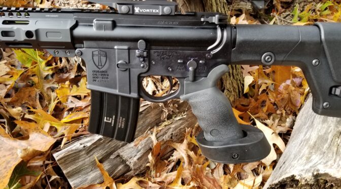
With the Alexander Arms (AA) .50 Beowulf DIY Upper comes one actual Beowulf magazine built to AA’s specifications by E-Lander Magazines of Israel. This gave me a chance to see what they did differently to support the ‘Wulf and it comes down to a relief in the front of the otherwise normal AR magazine. This allows the shoulder of the cartridge to pass by without hanging up on its way towards the chamber. Everything else appeared the same in terms of the feed lips and the follower.
E-Lander of Israel makes the Beowulf magazines for Alexander Arms. One is included with the DIY Upper Kit.This is the top front of the E-Lander magazine. Note the notched out area. On a normal AR magazinet his goes straight across,
So, armed with how basic this was, it immediately hit me that a flap sander could make a quick angled surface faster than the drum mag. So, I loaded up a 3/8″ 120 grit flap sander with a 1/8″ shank into my bench rotary tool.
The magazines I convert are D&H 5.56/.223 magazines that Palmetto State Armory sells. They are reliable and well made plus they are very affordable with sales prices starting around $8.99 and normal price around $12.99 for buyers in a rush. They also have regular combo deals such as a case and seven mags for $89.99. You have to love PSA’s deals. Click here to see what they have.
The first step is to remove the floor plate of the magazine. On these D&H magazines from PSA, I just use a screw driver to lift the floor plate for the tabs to clear the magazine body. Pull the floor plate off while trapping the magazine spring. Remove the floor plate, spring and follower so they are out of your way.
I slide a small screw driver between the magazine body and the bottom plate to then lift and remove the plate from the magazine. Note, the magazine spring will come fling out.See the tabs/ridges stamped in the floor plate? That is why you need to use the screw driver to lift the plate so those tabs can clear the magazine body.Any rotary too will use. This is my benchmounted unit that I use on grips and what not, Any Dremel or other rotary tool would work.
So you basically use the flap sander to to cut a ramp on the inside edge of the magazine. You do not need to replicate the notch – just use the flap sander to quickly remove the material.
The left magazine is an original unmodified magazine. The middle has the ramp cut and the right unit has been reassembled. Be sure to blow out the mags before reassembly.
Using the flap sander can get the job done in 30 seconds or so – it’s literally that fast. Be sure to blow out the magazine bodies to remove all of the grit before you reassemble them. Failure to do so may cause you problems later either with the magazine failing or getting into the rifle.
The final step is to test each magazine to make sure it feeds properly. Load two rounds to test chambering in a safe place with the muzzle pointed in a safe direction. Never take a risk.
That’s all there is to it. You can convert a magazine faster than the time it took you to read this post. I hope it helps you out.
If you find this post useful, please share the link on Facebook, with your friends, etc. Your support is much appreciated and if you have any feedback, please email me at in**@*********ps.com. Please note that for links to other websites, I may be paid via an affiliate program such as Avantlink, Impact, Amazon and eBay.