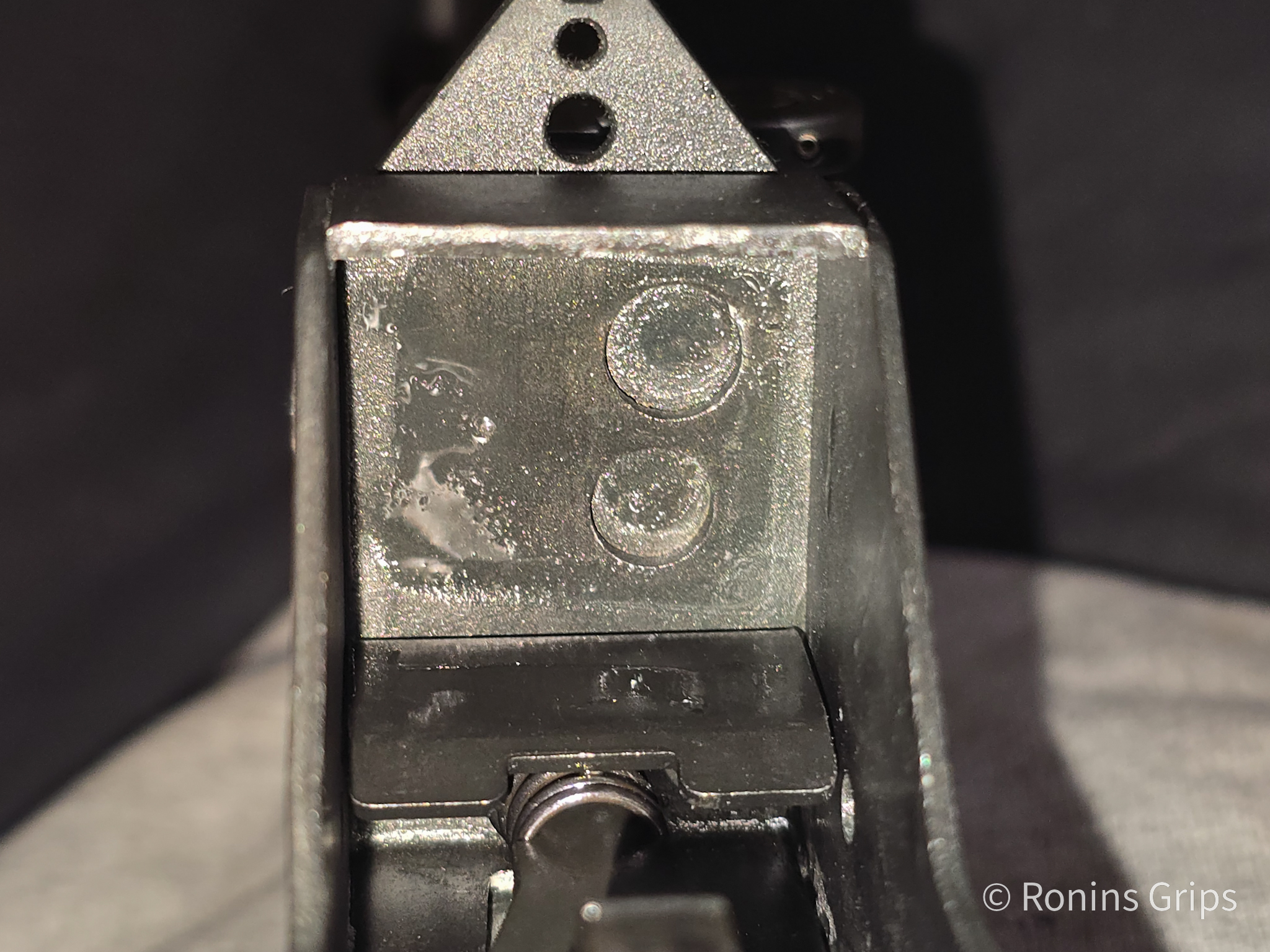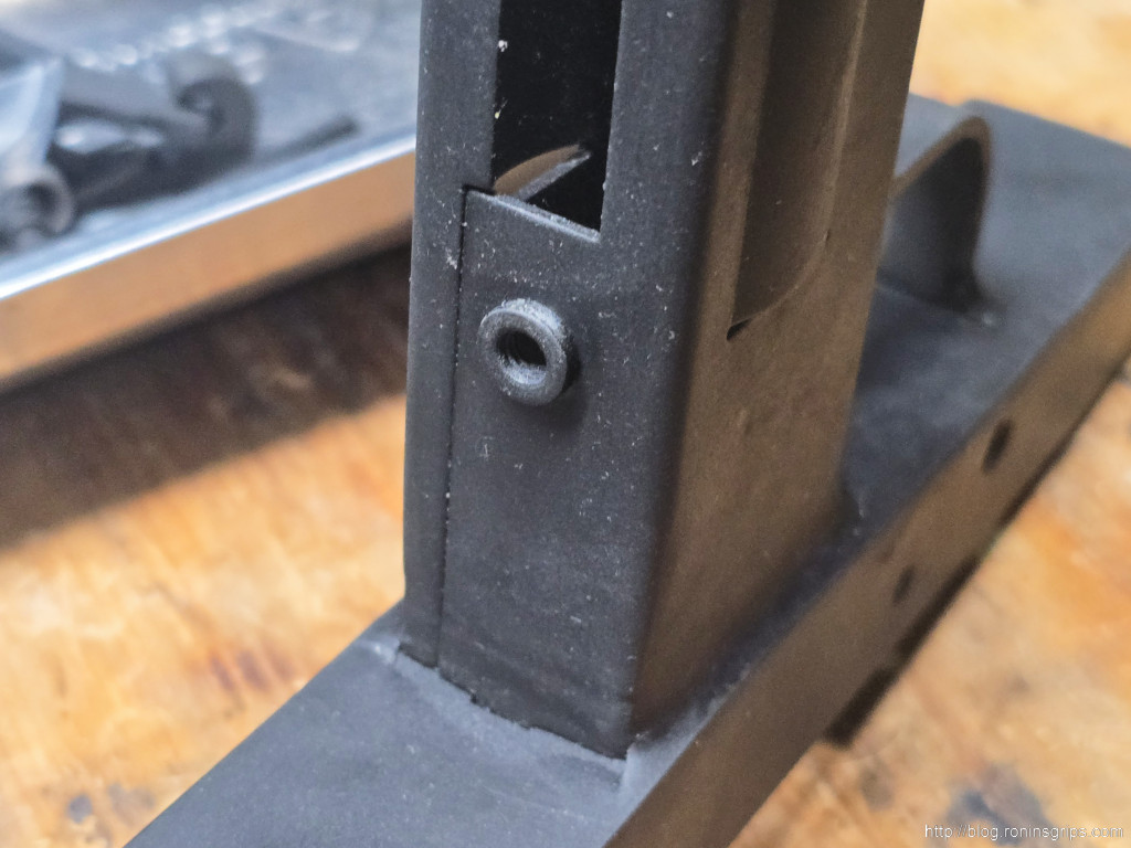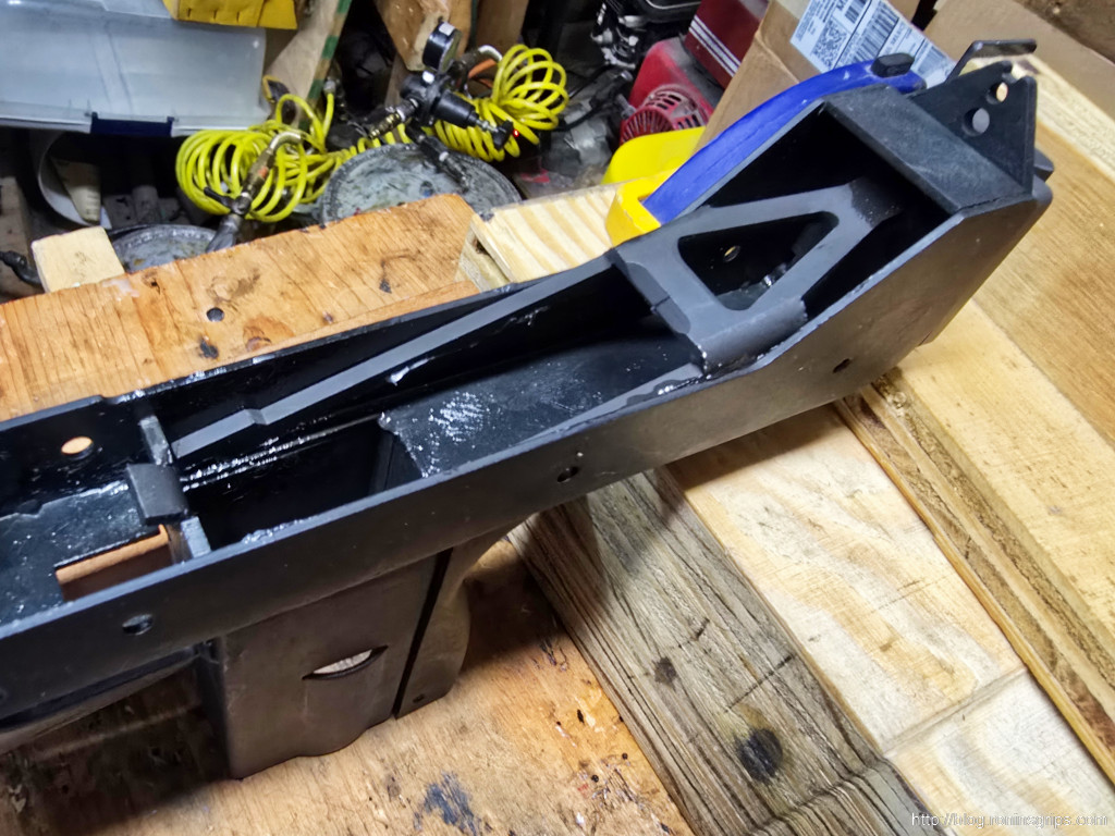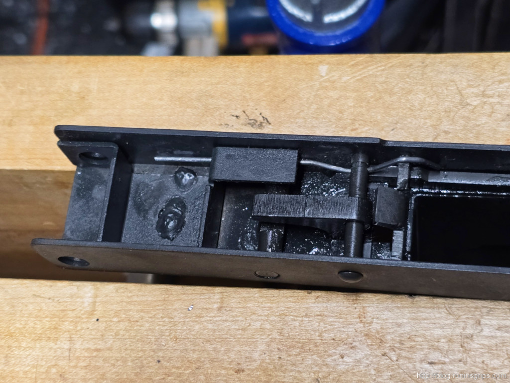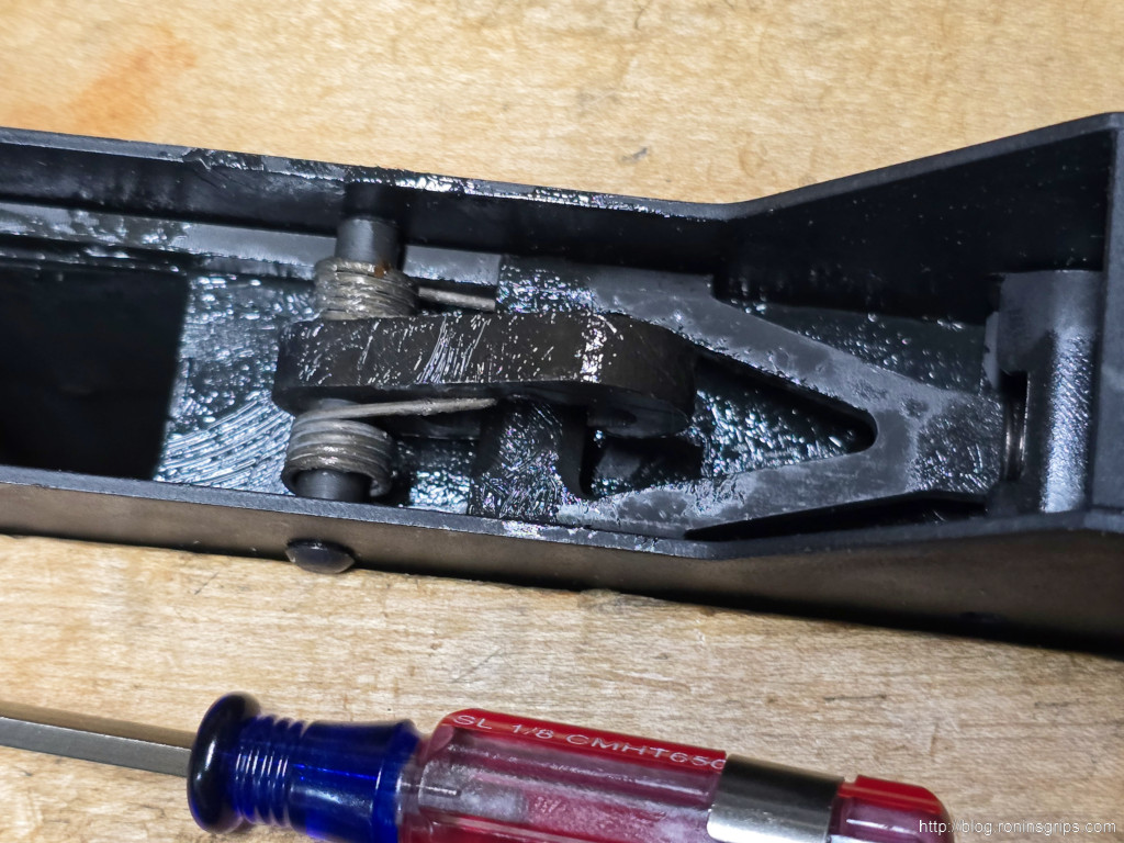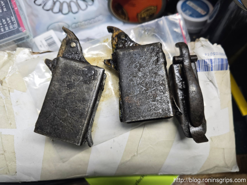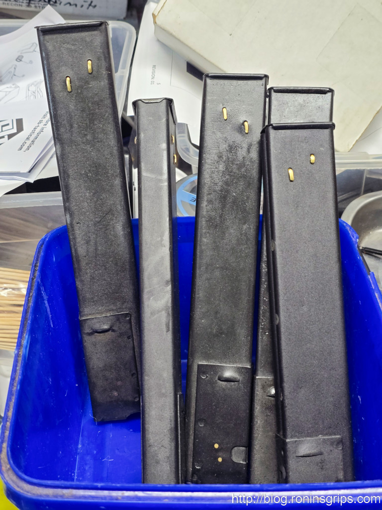
For any collector of 20th-century military surplus firearms, the experience is a familiar one: opening a wooden crate or unwrapping a paper-and-oilcloth bundle to reveal a piece of history, entombed in a thick, sticky, amber-to-dark-brown grease. This ubiquitous substance, the bane of many an enthusiast, is the primary barrier between acquiring a historical artifact and rendering it a functional firearm.1 In the United States and the broader Western world, this preservative is almost universally known by the genericized trademark “Cosmoline.” However, when dealing with arms originating from the former Soviet Union and its client states, this term is a misnomer. The waxy preservative slathered on everything from Mosin-Nagant rifles to SKS carbines and Kalashnikov parts kits is a distinct substance, developed and standardized under a completely different system to meet a unique set of strategic and environmental challenges.
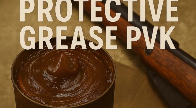
The true subject of this analysis is the primary Soviet-era long-term corrosion inhibitor, known officially as Смазка защитная ПВК (Smázka zashchítnaya PVK), which translates to “Protective Grease PVK”.3 While this is its technical designation, it is far more widely known by its colloquial name:
пушечное сало (pushechnoye salo), or “cannon lard”.3 This evocative nickname is a critical first clue to understanding the material’s context.
The term ‘salo’ holds a deep cultural significance in Russia, Ukraine, and other Slavic nations. It refers to slabs of cured pork fatback, a traditional and enduring food staple, particularly valued for its high energy content and long shelf life.6 The preservative’s thick, greasy, and often off-white to yellowish-brown appearance bore a striking resemblance to this familiar food item, leading soldiers and depot workers to adopt the practical and descriptive moniker “cannon lard.”
This act of naming military equipment after a mundane, greasy object is not unique to the Soviet experience. It reveals a fundamental aspect of soldiering culture that transcends ideology and national borders. A striking parallel can be found in the American military’s nickname for the M3 submachine gun. Due to its simple, stamped-metal construction and resemblance to a common mechanic’s tool, the M3 was almost universally dubbed the “Grease Gun”.10 In both cases—”cannon lard” and “grease gun”—the premier military powers of the Cold War independently arrived at similar colloquialisms rooted in the practical, unglamorous, and greasy realities of their equipment. This is not a mere coincidence; it reflects a shared “grunt-level” perspective, where soldiers relate to the tools of their trade not through official nomenclature but through visceral, descriptive, and often slightly pejorative terms. Understanding this parallel provides a humanizing context for the technical analysis that follows, grounding the chemistry and doctrine in the everyday language of the men who used these weapons.
Section 2: A Comparative Analysis: Soviet ПВК vs. American Cosmoline
To fully understand pushechnoye salo, it is essential to analyze its specific formulation and properties, contrasting them with the American product that has lent its name to the entire category of military preservatives. This comparison reveals two parallel yet distinct technological solutions to the common problem of long-term metal preservation.
The Soviet Standard: ГОСТ 19537-83 and Смазка ПВК
The production and quality of pushechnoye salo were governed by a strict state standard, or ГОСТ (Государственный стандарт). The primary standard for this grease was ГОСТ 19537-83, which superseded earlier versions like ГОСТ 10586-63 and ГОСТ 3005-51.3 GOST standards were mandatory benchmarks in the Soviet Union, ensuring uniformity and quality control across its vast industrial base.
Chemical Composition: According to GOST 19537-83, Смазка ПВК is a carefully formulated compound, not a simple grease. Its primary components are 4:
- Base: A fusion of петролатум (petrolatum), a semi-solid mixture of hydrocarbons also known as petroleum jelly, and a viscous mineral oil. The specific type of petrolatum used could affect the final color, with some batches appearing light-yellow rather than the more common brown.
- Additives: To enhance its protective properties, two key additives were introduced. The first is 5% церезин (ceresin), a refined, hard mineral wax derived from ozokerite, which increases the grease’s melting point and consistency. The second, and more critical, is the corrosion-inhibiting additive МНИ-7 (MNI-7). Technical sources identify MNI-7 as an oxidized ceresin, which improves the grease’s ability to adhere to surfaces and provides active anti-corrosion properties.
Physical Properties: The formulation of ПВК resulted in a set of physical characteristics tailored for the Soviet military’s specific needs 4:
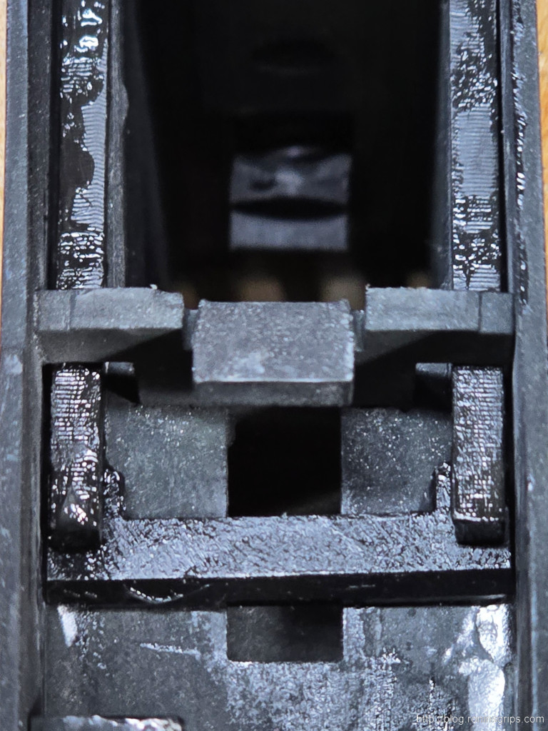
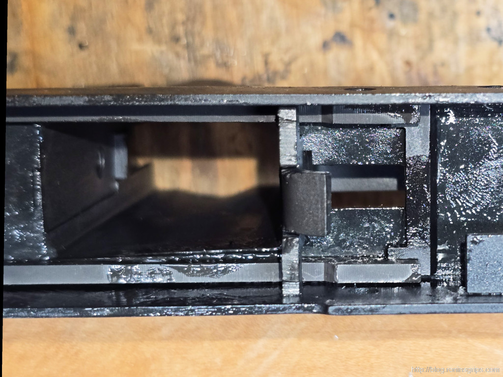
- Appearance: A thick, highly adhesive, sticky ointment, typically brown in color.
- Thermal Behavior: The grease has a relatively low melting point, beginning to soften and flow at temperatures above 50°C (122°F). This property is crucial for its application, which was typically done by dipping heated parts into a molten vat of the grease. The MNI-7 additive was particularly important for improving its thixotropic properties, helping it to cling to vertical surfaces without slumping off entirely.
- Cold Weather Performance: This is arguably the most critical feature of ПВК. While the grease becomes extremely thick and loses all mobility below 10°C (50°F), making cold application nearly impossible, it crucially retains its protective, corrosion-inhibiting film integrity down to -50°C (-58°F). At these extreme temperatures, it does not crack or flake away, ensuring the metal beneath remains sealed.
- Water Resistance: Like all hydrocarbon-based greases, ПВК is completely insoluble in water. Its formulation provides exceptionally high water resistance, physically blocking moisture from reaching the metal surface, which is the cornerstone of its preservative capability.
The American Counterpart: MIL-C-11796C and Cosmoline
The substance known as Cosmoline has its own distinct history and specifications. It was originally developed by the chemical company Houghton International in the 1860s or 1870s, not as a rust preventive, but as a pharmaceutical product. It was used as a versatile ointment for everything from disinfecting wounds and treating veterinary ailments to promoting hair growth.12 Its transition to military use occurred when it received a government specification as a rust preventive, and it was subsequently used to protect equipment from the Spanish-American War through the Vietnam War.12
The modern standard for this type of preservative is U.S. Military Specification MIL-C-11796C, Class 3.
Chemical Composition: Chemically, Cosmoline is described as a homogenous mixture of oily and waxy long-chain, non-polar hydrocarbons. Its primary ingredient is a volatile aliphatic petroleum solvent.12 This solvent keeps the compound in a viscous, grease-like state when fresh but is designed to slowly evaporate over time, leaving behind the more solid, waxy hydrocarbon protective layer.
Physical Properties:
- Appearance: Cosmoline is consistently brown in color, though its viscosity can vary.12
- Thermal Behavior: It has a melting point of 45–52°C (113–126°F), remarkably similar to its Soviet counterpart, ПВК. Its flash point is 185°C (365°F).12 This similar melting range indicates that both the US and Soviet militaries arrived at a similar thermal window for a grease that was stable in most ambient conditions but could be easily liquefied with moderate heat for application and removal.
Table 1: Comparative Properties of Soviet ПВК vs. American Cosmoline
| Property | Soviet Смазка ПВК | American Cosmoline |
| Official Designation | Смазка защитная ПВК (Protective Grease PVK) | Preservative and Sealing Compound |
| Governing Standard | ГОСТ 19537-83 3 | MIL-C-11796C, Class 3 12 |
| Colloquial Name | пушечное сало (Cannon Lard) 3 | Cosmoline 12 |
| Primary Chemical Base | Petrolatum and viscous mineral oil 4 | Long-chain, non-polar hydrocarbons 12 |
| Key Additives | Ceresin (mineral wax), MNI-7 (oxidized ceresin) 4 | Aliphatic petroleum solvent (volatile) 12 |
| Color | Brown or light-yellow 4 | Brown 12 |
| Melting Point | >50°C (122°F) 4 | 45–52°C (113–126°F) 12 |
| Effective Low-Temp Range | Protects down to -50°C (-58°F) 4 | Not specified, but used in global conflicts |
| Primary Application | Hot-dip immersion | Hot-dip, brushing, or spraying |
Section 3: The Doctrine of Preservation: Why the Red Army Greased Everything
The ubiquitous presence of pushechnoye salo on Soviet-bloc military hardware was not a matter of simple maintenance preference. It was the direct, tangible result of a deeply ingrained military doctrine shaped by geography, history, and the existential threat of the Cold War. The grease itself is an artifact of a strategic philosophy that prioritized mass, endurance, and readiness for a conflict of unimaginable scale.
Strategic Depth and Long-Term Storage
Soviet military doctrine during the Cold War was fundamentally oriented toward preparing for a massive, protracted, and highly attritional ground war against the combined forces of NATO.15 This was not a strategy built around short, decisive conflicts, but one that anticipated a continent-spanning struggle that would require the total mobilization of the state’s resources over a long period. This doctrine of “deep operation” and continuous combat necessitated the production and storage of immense quantities of military materiel. For every tank, rifle, and artillery piece in active service, there were many more held in strategic reserve, ready to equip wave after wave of mobilized divisions.18
This created a colossal logistical challenge: millions of weapons, vehicles, and spare parts had to be preserved in a state of readiness for years, or even decades, awaiting the call to war. The primary enemy during this long wait was not a foreign power, but the slow, relentless process of corrosion. A rifle that has rusted in a depot is as useless as one destroyed in battle. Therefore, a cheap, effective, and reliable long-term preservative was not just a convenience; it was a cornerstone of Soviet strategic readiness.
Warfare in a Harsh Climate
The physical properties of Смазка ПВК were meticulously tailored to the geographic and environmental realities of the Soviet Union and its likely theaters of war. The operational landscape stretched from the humid shores of the Black Sea to the frozen tundra of the Arctic Circle. The disastrous experience of the German Wehrmacht during Operation Barbarossa served as a powerful, enduring lesson for Soviet planners. In the winter of 1941, standard German lubricants for everything from machine guns to tank engines froze solid, crippling their war machine at the gates of Moscow.19
The Soviets learned this lesson intimately. The specification that ПВК must maintain its protective integrity without cracking or flaking at temperatures down to -50°C (-58°F) was a direct response to this historical reality.4 It was a critical design requirement, ensuring that weapons pulled from a frozen Siberian depot would be protected from corrosion until they could be de-preserved and issued. This institutional focus on extreme cold-weather operations was evident in many areas of Soviet practice, such as the field-expedient technique of thinning engine oil with gasoline to start tanks and aircraft in sub-zero temperatures.20
A System, Not a Substance: The ЕСЗКС
It is crucial to understand that Смазка ПВК did not exist in a vacuum. It was one component within a vast, highly structured, and state-mandated framework known as the ЕСЗКС (Единая система защиты от коррозии и старения), or the “Unified System of Corrosion and Ageing Protection”.21 This system, codified in a library of interlocking GOST standards, governed every aspect of material preservation for the entire Soviet state, from military hardware to industrial machinery.
The existence of numerous related standards, such as ГОСТ 9.054-75, which detailed the accelerated testing methods for preservative oils and greases, and ГОСТ 10877-76, which specified a different type of preservative oil known as К-17, demonstrates the system’s depth and complexity.21 The ЕСЗКС prescribed specific types of oils, greases, inhibited papers, and polymer films for different metals, alloys, and storage conditions. It was a holistic, centrally planned approach to defeating material degradation.
This systemic approach reveals the true significance of preservation in Soviet strategic thought. The development and rigid standardization of materials like ПВК were not mundane maintenance tasks. They were a direct expression of a military doctrine predicated on winning a long war through industrial endurance and the overwhelming force of mobilized reserves. In this context, the ability to store millions of rifles for fifty years in perfect condition was as vital to national defense as the ability to manufacture new tanks. The thick, stubborn grease found on a surplus Mosin-Nagant today is, therefore, more than just gunk; it is a physical remnant of Cold War strategic planning, a monument to a philosophy that equated preservation with power.
Section 4: The Aging Process: From Viscous Grease to Hardened Shell
The effectiveness of preservatives like Смазка ПВК and Cosmoline is finite. Over decades of storage, their physical and chemical properties change, transforming them from a pliable grease into the hardened, waxy shell that collectors know well. This aging process was an understood and accepted part of long-term storage doctrine.
Mechanisms of Aging: Evaporation and Oxidation
The hardening of these preservatives is primarily driven by two chemical processes:
- Solvent Evaporation: American Cosmoline, in particular, is formulated with a volatile aliphatic petroleum solvent.12 This solvent is designed to keep the preservative in a viscous, easily applicable state. Over time, especially with exposure to air, these volatile organic compounds (VOCs) evaporate.12 As the solvent fraction dissipates, what remains is the much harder, wax-like hydrocarbon base, which solidifies on the metal’s surface.12 This process can begin within a few years of air exposure.12
- Oxidation: All petroleum-based lubricants, including the base oils in ПВК and Cosmoline, are susceptible to oxidation—a chemical reaction with atmospheric oxygen.50 This process is accelerated by heat and the presence of metal contaminants, which act as catalysts.50 Oxidation breaks down the lubricant’s base oil and depletes its protective additives, leading to an increase in viscosity, the formation of organic acids, and eventually sludge and varnish.51 While both preservatives contain antioxidant additives to slow this process, over many decades, oxidation contributes to the overall hardening and degradation of the protective film.50
Intended Lifespan and the Reality of Strategic Reserves
Soviet military planners, operating under a doctrine of preparing for a prolonged, attritional war, intended for their equipment to be preserved for many decades.53 The goal was not a commercial shelf life of a few years, but a strategic one that could last indefinitely until the materiel was needed.53 Evidence from recent conflicts, where Russia has pulled tanks and artillery from storage that date back to the 1960s, ’50s, or even ’40s, confirms that the intended preservation period was at least 50 to 80 years.55
While modern commercial rust preventatives often list a shelf life of 2 to 5 years, this is a guarantee for optimal performance under specified conditions.56 The actual effective lifespan of military-grade preservatives, especially when hermetically sealed away from open air, is vastly longer.12 The Soviets understood that the grease would age and harden, but this was an acceptable trade-off for multi-decade corrosion protection.53
The Challenge of Hardened Preservative: Then vs. Now
The difficulty of removing these preservatives is directly related to their age and storage conditions. This creates a significant difference between the original Raskonservatsiya process and the task facing a modern collector.
- Ideal Timeframe (Fresh Application): When freshly applied or removed from sealed storage, both ПВК and Cosmoline are in their intended viscous, grease-like state. In this condition, the preservative can be largely removed by simply wiping it off with a rag, with minimal need for aggressive solvents.12 This is the scenario for which the simple Soviet field protocol was designed.
- Modern Challenge (Aged Application): After decades of exposure to air, the preservative has solidified into a hard, waxy varnish.12 This hardened shell does not wipe off easily and is resistant to simple manual cleaning. It requires laborious scraping or, more effectively, the application of heat to melt the wax and chemical solvents to dissolve the hardened hydrocarbons.12 This is why modern removal methods involving heat guns, boiling water, solvents, and ultrasonic cleaners are not just for convenience—they are a necessity to overcome the chemical changes the preservative has undergone over 50+ years.
Section 5: The Official Soviet Method: Расконсервация per GOST 9.014-78
Just as the application of preservatives was rigidly standardized, so too was their removal. The official process, known as Расконсервация (Raskonservatsiya)—literally “de-preservation” or “de-mothballing”—was designed for simplicity, scalability, and execution by conscript soldiers with minimal specialized equipment. The general requirements for this process were laid out in the overarching standard ГОСТ 9.014-78, “Temporary corrosion protection of products. General requirements”.24
Reconstructing the Official Protocol
By analyzing ГОСТ 9.014-78 and related Russian-language military and technical manuals, the official field-level procedure for bringing a preserved weapon into service can be reconstructed. It was a pragmatic, multi-step process:
- Step 1: Mechanical Removal. The first and most intuitive step was the bulk removal of the preservative. Soldiers would use dry, clean rags (ветошью) or soft paper to wipe off as much of the thick, external layer of ПВК as possible.28 This removed the majority of the material without the use of any chemicals.
- Step 2: Solvent Application. For the thick, hardened grease that remained, especially in crevices and internal mechanisms, the use of a solvent was prescribed. The most commonly cited and widely available solvent for this task in the Soviet military was керосин (kerosene).29 The procedure did not typically involve soaking the entire weapon. Instead, a rag would be moistened with kerosene and used to wipe down the remaining preservative, dissolving it for easy removal.
- Step 3: Degreasing and Final Wiping. After the preservative was fully removed, the surfaces were wiped down with a degreasing agent (обезжиривателем) if available, and then thoroughly wiped with a clean, dry cloth to remove any solvent residue.28 This step was critical to ensure the surface was clean and dry before re-lubrication.
- Step 4: Re-lubrication. The final and most important step was the immediate application of a thin layer of standard-issue neutral gun oil (нейтрального оружейного масла).28 A surface freshly stripped of its heavy preservative by solvents is highly susceptible to flash rusting, so this re-application of a light, protective oil film was essential to prepare the weapon for service and protect it from short-term corrosion.
The Doctrine of “Good Enough” in Practice
The striking feature of the official Raskonservatsiya protocol is its sheer simplicity. It eschews complex chemicals, specialized heating apparatus, or electricity-dependent tools. This was not an oversight but a deliberate and intelligent design choice, reflecting a core tenet of Soviet operational philosophy: dostatochno, or sufficiency. The system was not designed to be the most elegant, the fastest, or the most forensically perfect method possible. It was designed to be the most robust, reliable, and effective method for the specific context of the Soviet military.
In a mass mobilization scenario, a procedure requiring sophisticated technology would be a logistical bottleneck and a critical point of failure. A process based on rags, kerosene, and elbow grease, however, is almost infinitely scalable. It could be performed by millions of conscripts with minimal training, in depots, rail yards, or forward assembly areas, using commonly available materials.32 The official Soviet method was the epitome of pragmatism—a “good enough” solution that guaranteed that a preserved rifle could be made ready for battle, anywhere, anytime.
Section 6: The Modern Armorer’s Guide: Top 5 Removal Methods Evaluated
While the official Soviet method was effective for its time and purpose, the modern firearms collector has access to a wider array of tools and chemicals that can make the process of Raskonservatsiya faster, easier, and more thorough. The following analysis evaluates the top five modern methods, including the heated ultrasonic technique, providing a practical guide for today’s enthusiast.
General Principles for All Methods
Before undertaking any removal process, several universal principles should be observed to ensure safety and effectiveness:
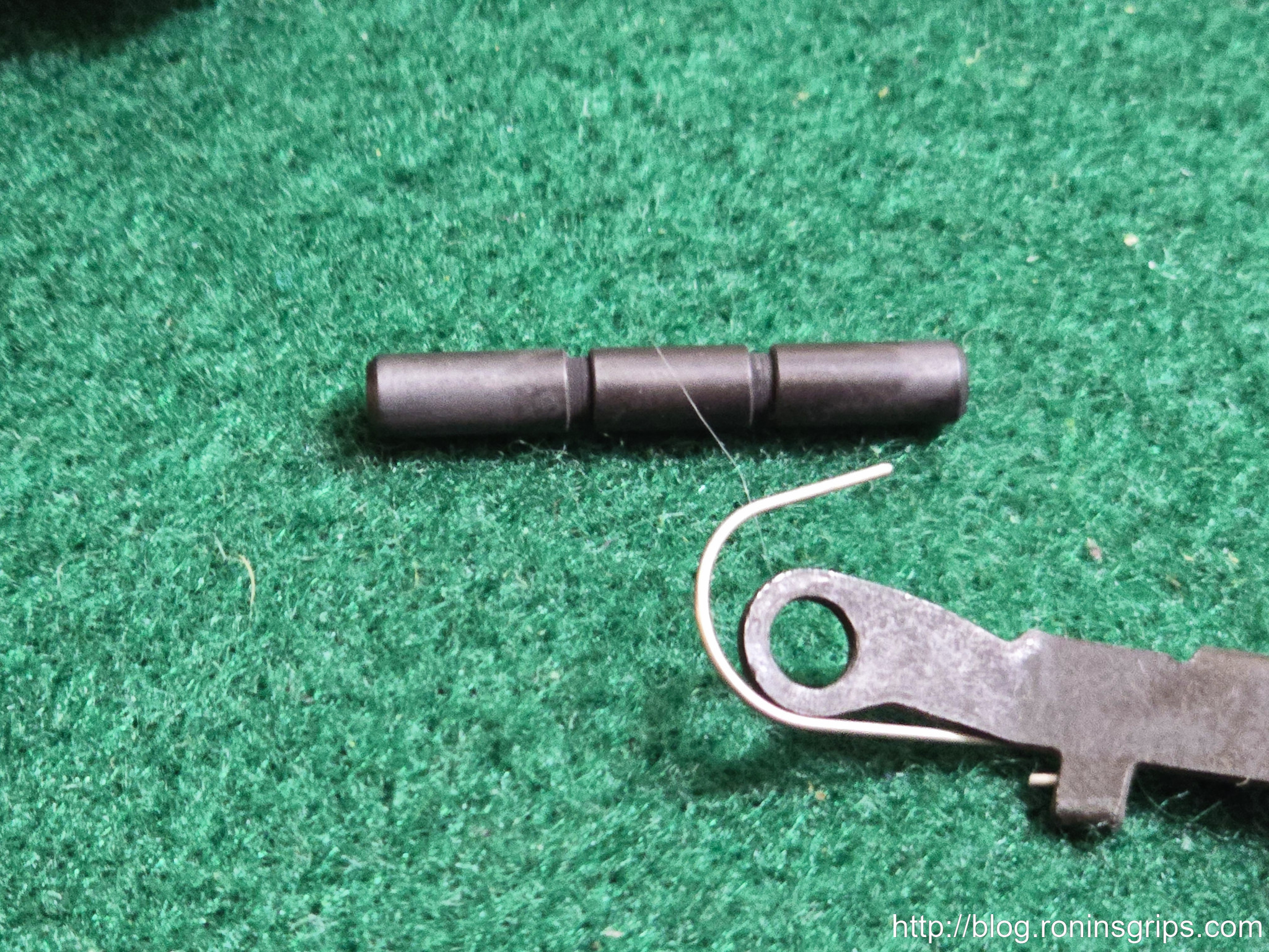
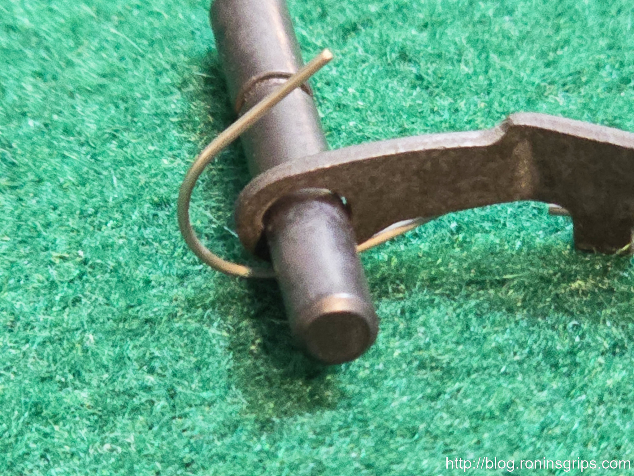
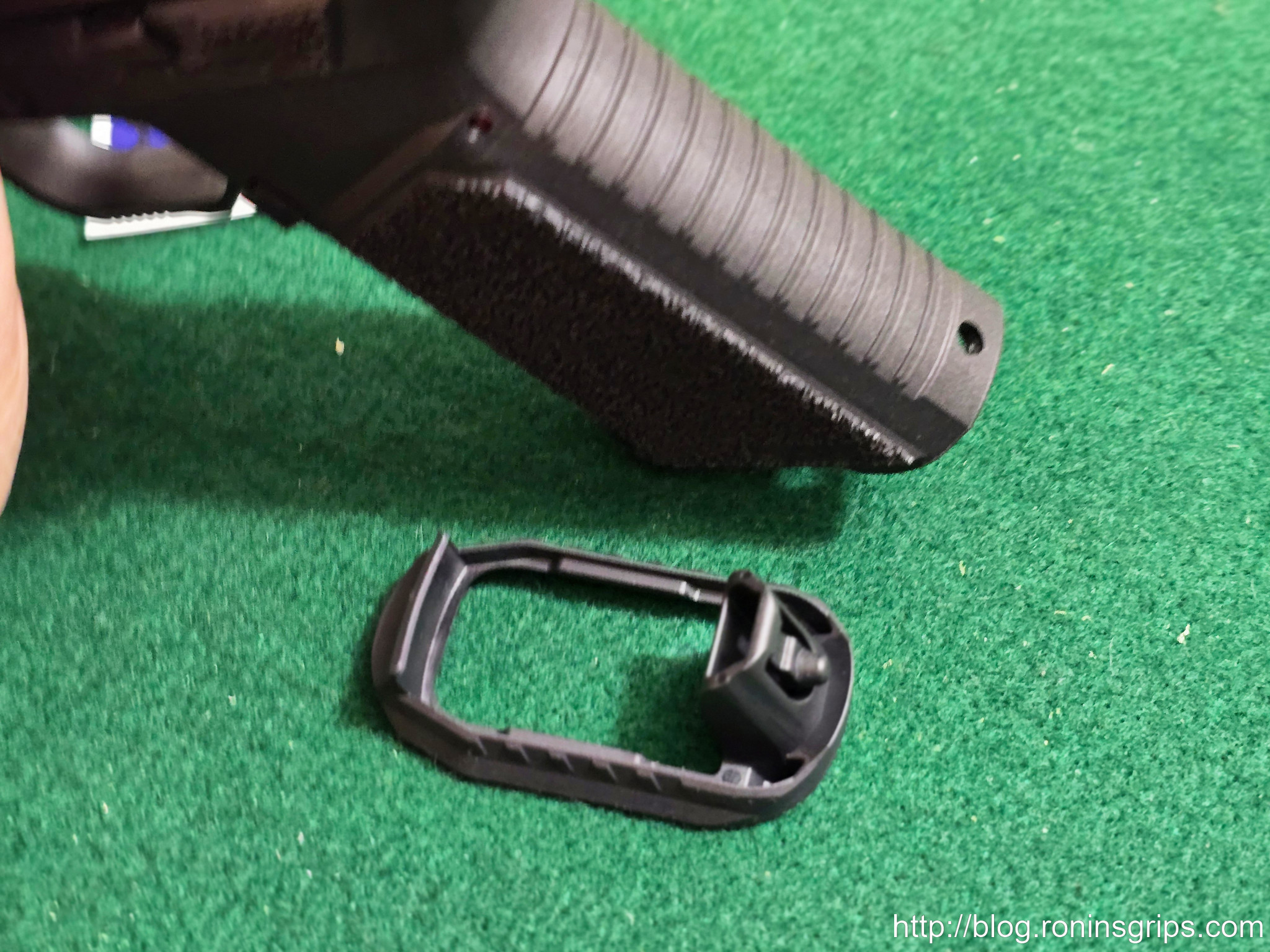
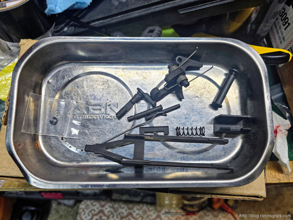
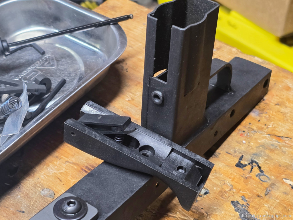
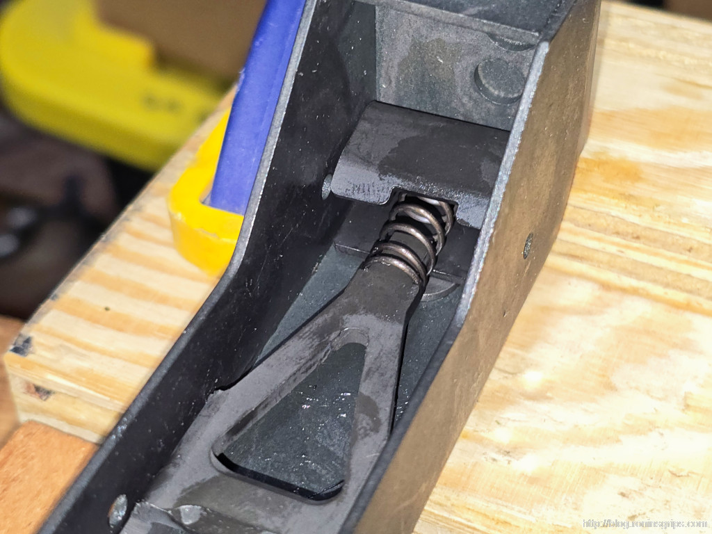
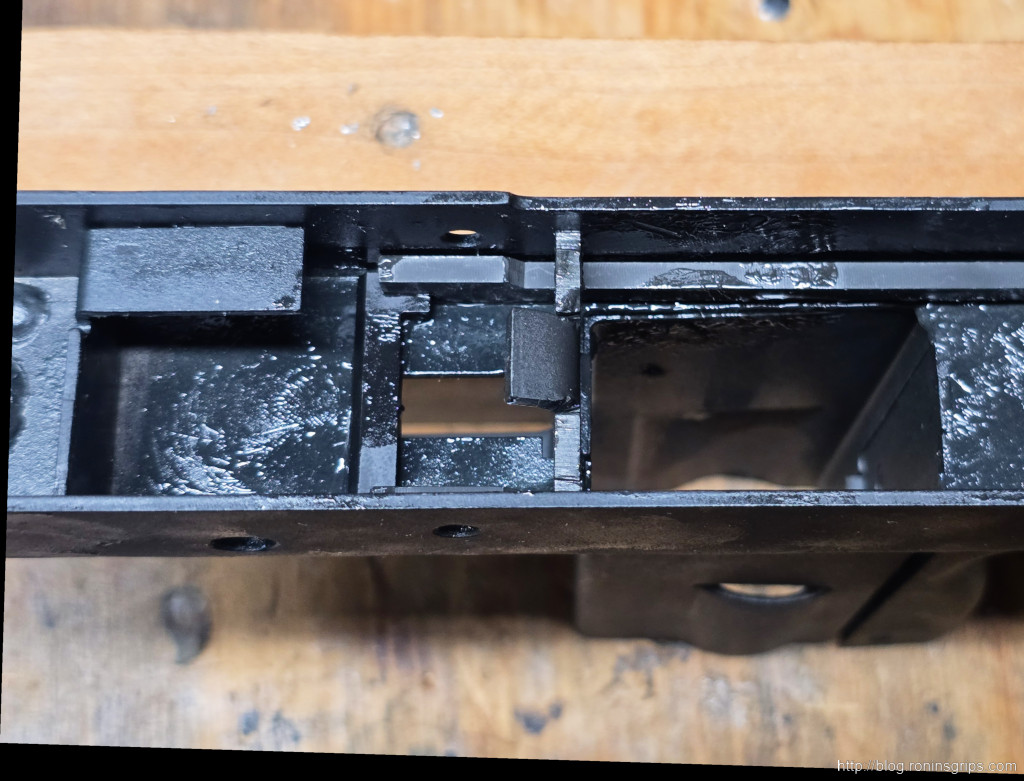
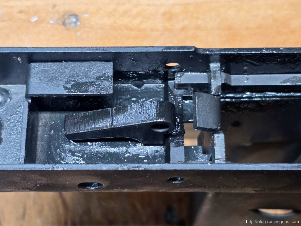
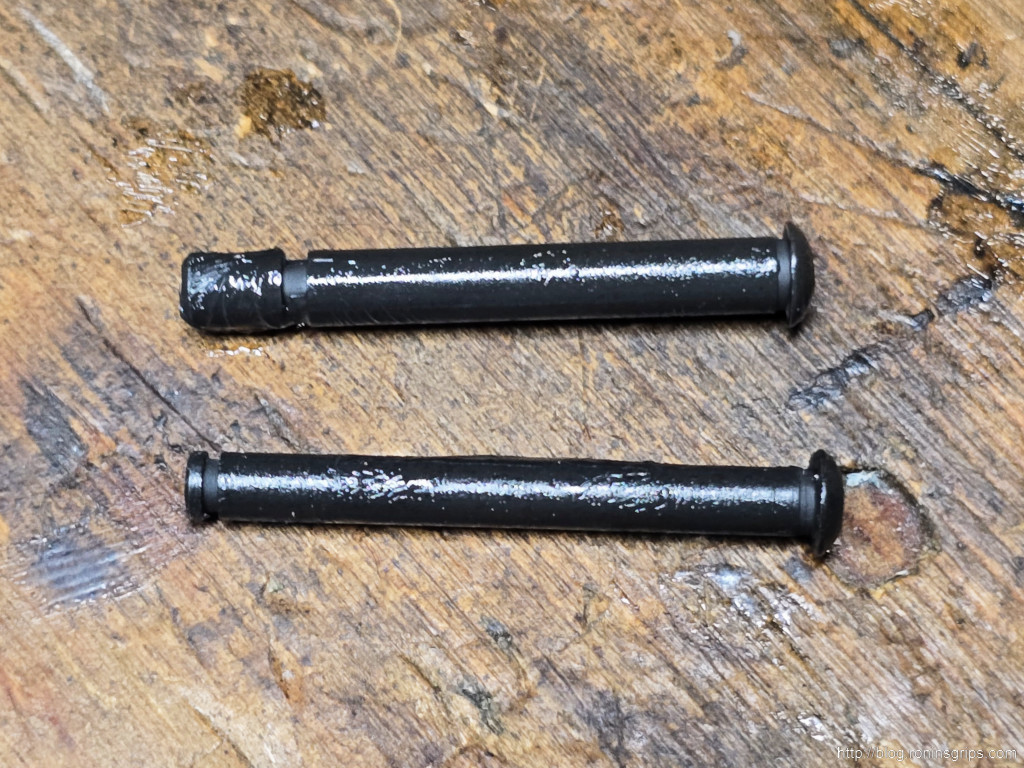
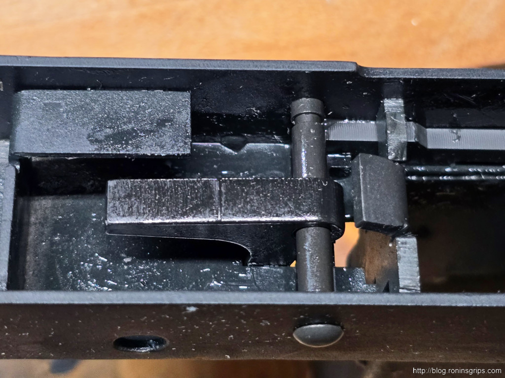
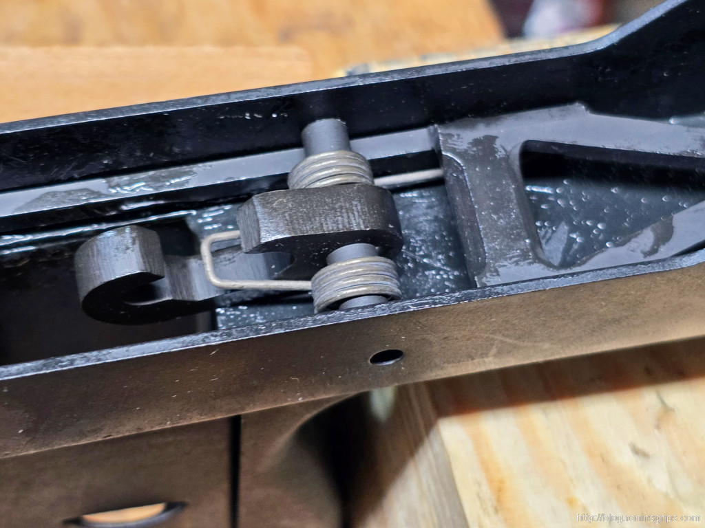
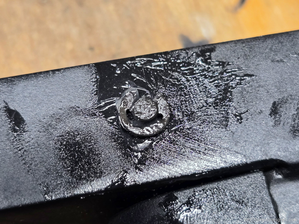
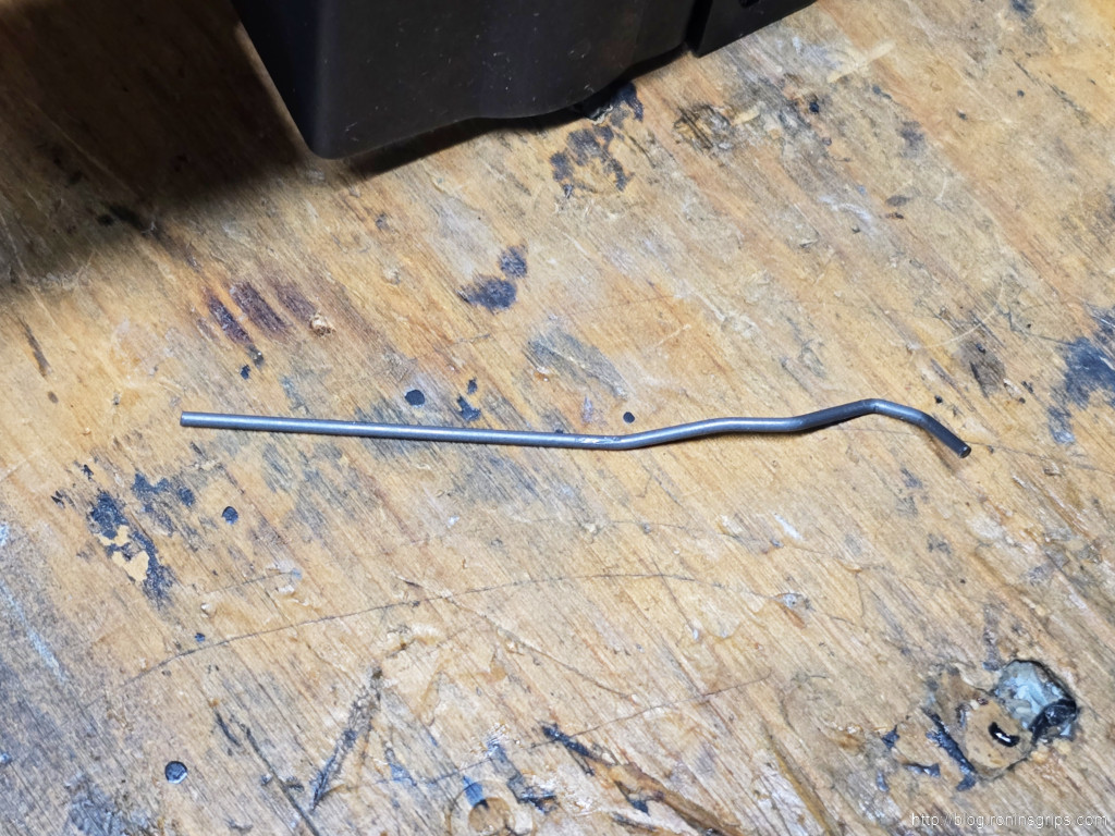
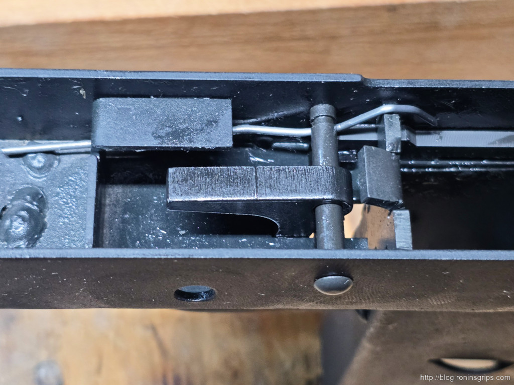
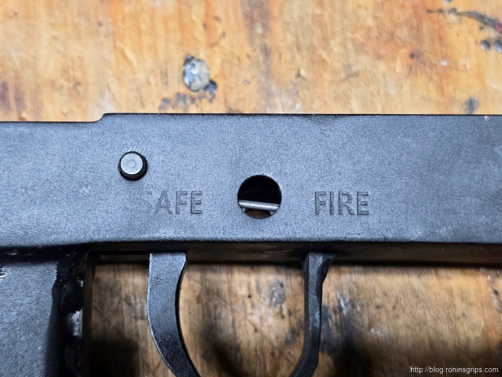
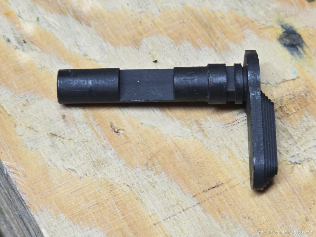
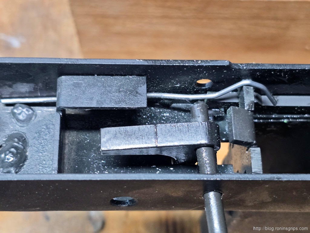
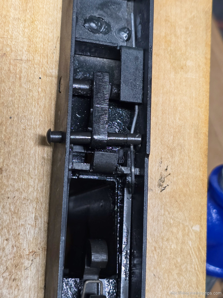
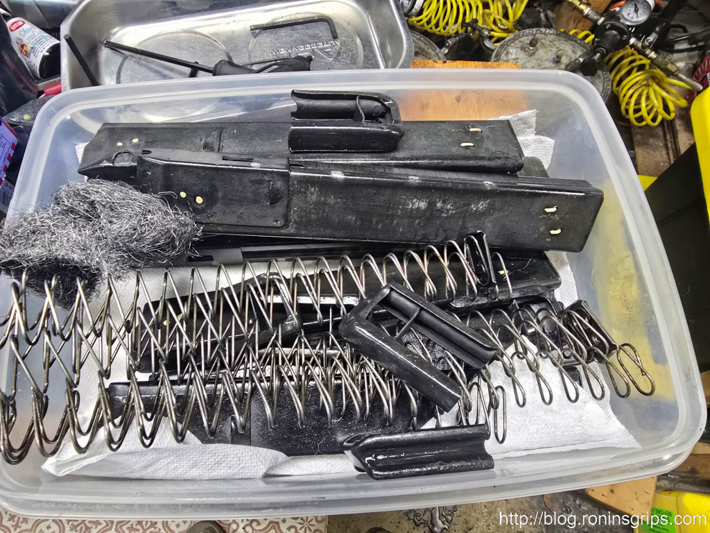
- Full Disassembly: For a thorough cleaning, the firearm must be completely disassembled. This allows access to all surfaces, including the bore, chamber, bolt internals, trigger group, and small pins and springs where preservative can hide and cause malfunctions.33
- Safety First: The work area must be well-ventilated, especially when using volatile solvents. Appropriate personal protective equipment (PPE), such as nitrile or other chemical-resistant gloves, is essential. When using flammable solvents like mineral spirits or kerosene, all ignition sources must be eliminated.33
- Proper Waste Disposal: The removed grease and solvent mixture is considered hazardous waste. It should never be poured down a drain or onto the ground. It will solidify and cause blockages, and it contaminates the environment. It should be collected and disposed of in accordance with local regulations for hazardous materials.12
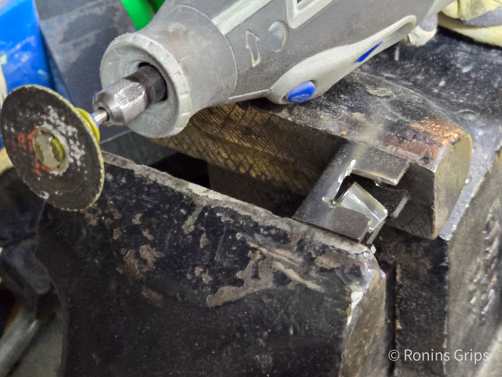
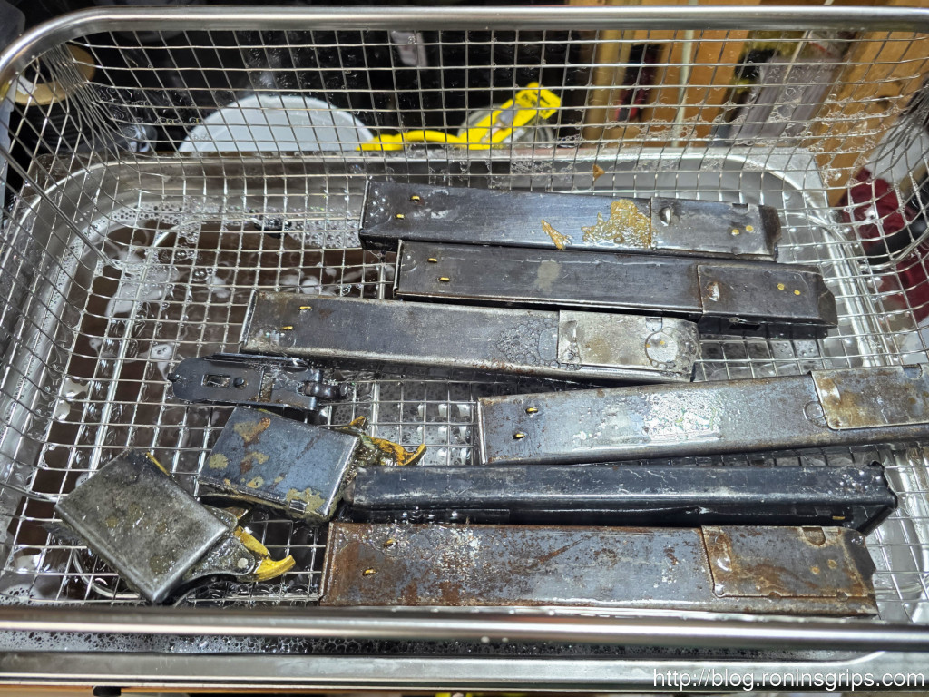
Method 1: Heated Ultrasonic Cleaning
This method, employed by the user who initiated this query, combines heat, water, a degreasing agent, and high-frequency sound waves to achieve a deep clean.
- Procedure: Disassembled metal parts are placed in the wire basket of an ultrasonic cleaner. The tank is filled with hot water and a water-based degreasing solution. Common choices include Simple Green, Zep Citrus Degreaser, or specialized gun cleaning concentrates like those from Hornady or Lyman.34 A dilution ratio of 1 part degreaser to 5 or 10 parts water is typical.34 The unit’s heater is engaged, and the ultrasonic transducer is run for several cycles (e.g., 5-15 minutes each), with parts being rearranged between cycles. The heat melts the
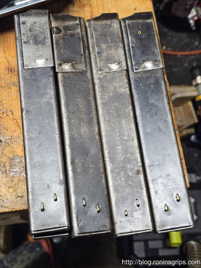
ПВК, while the ultrasonic cavitation creates microscopic bubbles that implode on the part’s surface, scrubbing away the liquefied grease from every corner, thread, and crevice. After cleaning, parts must be immediately and thoroughly rinsed with hot water, dried completely (compressed air is ideal), and coated with a water-displacing oil (like WD-40 or Brownell’s Water Displacing Oil) or a standard gun oil to prevent rapid flash rusting.34 - Analysis: This is arguably the most effective, efficient, and thorough method for cleaning metal parts. Its ability to penetrate and clean internal channels, such as firing pin holes and gas ports, is unmatched by manual methods.34 It is a validation of the user’s preferred technique.
- Caveats: This method requires a significant upfront investment in an ultrasonic cleaner of sufficient size and power; small, underpowered jewelry cleaners are not suitable.34 It is not safe for wood or most polymer parts. While generally safe for durable military finishes like bluing and parkerizing, there is some anecdotal concern that overly aggressive chemical solutions or excessive cleaning times could potentially harm delicate or worn finishes.37
Method 2: Solvent Immersion
This is a classic and highly effective chemical approach to dissolving the preservative.
- Procedure: Disassembled metal parts are fully submerged in a bath of a suitable petroleum-based solvent. The most highly recommended and effective solvents are mineral spirits and kerosene.1 Diesel fuel and even gasoline have been used, but their high flammability and noxious fumes make them significantly more hazardous.39 For long parts like barrels and receivers, a popular and efficient setup involves using a section of PVC pipe, capped at one end and filled with solvent.1 After a period of soaking, parts are removed and scrubbed with nylon brushes to remove the softened grease. Because solvents strip all oils from the metal, a thorough post-cleaning lubrication is absolutely critical.
- Analysis: An extremely effective method that chemically breaks down the preservative. It is less expensive in terms of initial equipment cost compared to ultrasonic cleaning.
- Caveats: This method involves the use of flammable and volatile chemicals, requiring extreme care regarding ventilation and ignition sources. It generates a significant volume of liquid hazardous waste that must be disposed of properly. The process is inherently messy.
Method 3: Thermal Application (Non-Immersion)
This method relies on heat to melt the preservative without submerging the parts in a liquid.
- Procedure: This technique varies for metal and wood.
- For Metal Parts: A heat gun on a low setting or a standard hair dryer can be used to gently and evenly heat disassembled parts, causing the grease to liquefy and drip off onto a collection surface like a cardboard box or aluminum foil.33 Some users place parts on wire racks in an oven set to a low temperature (e.g., 200-250°F or ~95-120°C), with a drip pan below.40
- For Wood Stocks: This is the premier method for removing the grease that has soaked deep into the wood grain. The stock is wrapped in absorbent material like paper towels or brown paper bags, then placed inside a black plastic trash bag. This assembly is then left in a hot environment, such as the dashboard of a car on a sunny day, or inside a homemade “hot box” constructed from a metal trash can and a low-wattage incandescent light bulb.1 The heat causes the grease to “sweat” out of the wood, where it is absorbed by the paper. The process is repeated with fresh paper until the wood no longer sweats grease.
- Analysis: An excellent, low-cost method for removing the bulk of the preservative with minimal use of chemicals. It is the safest and most effective method for cleaning original wood stocks without damaging them.
- Caveats: Poses a fire risk if parts are overheated with a heat gun or in an oven. Wood can be scorched or damaged if the heat is too intense or applied unevenly.32 The process can be slow and messy.
Method 4: Aqueous Immersion (Boiling Water)
This method uses the heat of boiling water to melt and separate the preservative.
- Procedure: Disassembled metal parts are placed in a large pot or tray (a metal wallpaper tray or a section of rain gutter works well for long parts) and covered with boiling water.32 The heat melts the
ПВК, which, being less dense than water, floats to the surface where it can be skimmed off. Adding a small amount of dish soap can help emulsify the grease. After removal from the water, the residual heat of the metal parts causes the water to evaporate very quickly, aiding in the drying process. - Analysis: This is a very low-cost, effective, and non-toxic method. It uses readily available materials and avoids flammable solvents.
- Caveats: This method is only suitable for metal parts that can be safely submerged in boiling water. There is an obvious risk of burns from the hot water and steam. Immediate and thorough drying and oiling are absolutely critical, as the bare, hot, wet steel will begin to flash rust almost instantly upon exposure to air.
Method 5: Manual Cleaning with Modern Degreasers
This is the most direct, hands-on approach, relying on “elbow grease” and modern cleaning agents.
- Procedure: This method involves physically scrubbing the preservative off using shop rags, nylon brushes, toothbrushes, Q-tips, and pipe cleaners, aided by a spray-on cleaning agent. A wide variety of products have been used successfully, including citrus-based degreasers, Simple Green, Dawn Powerwash foam, and even foaming bathroom cleaners like Scrubbing Bubbles.32 Some users employ harsher chemicals like brake cleaner, but this must be done with caution.40 The process is one of spraying, scrubbing, wiping, and repeating until the part is clean.
- Analysis: This method requires the least specialized equipment and is well-suited for firearms with only a light coating of preservative or for targeted touch-up cleaning after an immersion method.
- Caveats: It is by far the most labor-intensive and time-consuming method.1 It is difficult to achieve the same level of thoroughness in hard-to-reach areas compared to immersion techniques. Harsher chemicals like brake cleaner can damage wood, plastics, and some painted or delicate metal finishes.40
Table 2: Ranking of Modern Removal Methods
| Method | Effectiveness | Safety | Cost (Initial) | Speed | Primary Application |
| Heated Ultrasonic Cleaning | 5/5 | 4/5 | 1/5 | 5/5 | Metal Parts |
| Solvent Immersion | 5/5 | 2/5 | 3/5 | 4/5 | Metal Parts |
| Thermal Application | 4/5 | 3/5 | 4/5 | 2/5 | Metal & Wood |
| Aqueous Immersion (Boiling) | 4/5 | 3/5 | 5/5 | 3/5 | Metal Parts |
| Manual Degreasing | 3/5 | 4/5 | 5/5 | 1/5 | Metal & Wood (Light) |
| Ratings are on a 1-5 scale, where 5 is highest/best. |
Section 7: Conclusion and Recommendations
This analysis has deconstructed the substance colloquially known as “Cosmoline” in the context of Soviet-bloc firearms, identifying it correctly and placing it within its proper historical, chemical, and doctrinal framework. The investigation yields several key conclusions for the collector and historian.
Summary of Findings:
- The primary long-term preservative used by the Soviet military was not Cosmoline, but a distinct substance designated Смазка ПВК, governed by ГОСТ 19537-83. Known colloquially as pushechnoye salo (“cannon lard”), it is a petrolatum-based grease fortified with ceresin wax and an oxidized ceresin corrosion inhibitor.
- The development and widespread use of this specific preservative was a direct consequence of Soviet military doctrine. This doctrine anticipated a protracted, large-scale war, necessitating the long-term strategic storage of millions of weapons. The preservative’s exceptional performance in extreme cold was a critical requirement born from the harsh geography of the USSR and the hard-learned lessons of the Second World War.
- Over decades, these preservatives age and harden due to the evaporation of volatile solvents and chemical oxidation. This hardening process is why modern, aggressive cleaning methods are necessary, as the original, simple field-cleaning protocols are insufficient for the solidified material found on surplus firearms today.12
- The official Soviet removal procedure, Raskonservatsiya, was a model of pragmatic simplicity, designed for execution by conscript soldiers using common materials like rags and kerosene. Modern collectors, however, have access to a variety of more advanced and thorough techniques.
Final Verdict on the “Best” Method:
For the serious collector or armorer seeking the most thorough and efficient cleaning of disassembled metal firearm components, heated ultrasonic cleaning represents the current pinnacle of technology and effectiveness. It offers unparalleled deep-cleaning capabilities, especially for intricate parts and internal channels, validating the method preferred by the user who prompted this report.
However, no single method is universally perfect for all parts of a firearm. Therefore, the optimal strategy is often a hybrid approach:
- Use the Thermal Application method (e.g., the “sun and black bag” technique) to safely sweat the preservative out of the wooden stock and handguards.
- Use Heated Ultrasonic Cleaning for all disassembled metal parts to achieve a forensically clean state.
- Follow up with a meticulous manual inspection and touch-up, immediate and thorough drying, and a proper application of high-quality gun oil to all metal surfaces.
This combined methodology leverages the strengths of each technique, ensuring that a historical artifact is not only cleaned but properly conserved for its next chapter of life in the hands of a collector.
Glossary of Key Russian Terms
- Смазка ПВК (Smázka PVK): “Protective Grease PVK.” The official designation for the primary Soviet long-term firearms preservative.
- пушечное сало (pushechnoye salo): “Cannon Lard.” The widespread colloquial name for Смазка ПВК.
- ГОСТ (GOST): Государственный стандарт or “State Standard.” The system of mandatory technical standards in the Soviet Union.
- ЕСЗКС (YeSZKS): Единая система защиты от коррозии и старения or “Unified System of Corrosion and Ageing Protection.” The comprehensive state-level system for material preservation.
- Расконсервация (Raskonservatsiya): “De-preservation” or “De-mothballing.” The process of removing preservative grease to make equipment ready for service.
- керосин (kerosín): Kerosene. The standard field solvent used for Raskonservatsiya.
If you find this post useful, please share the link on Facebook, with your friends, etc. Your support is much appreciated and if you have any feedback, please email me at in**@*********ps.com. Please note that for links to other websites, we are only paid if there is an affiliate program such as Avantlink, Impact, Amazon and eBay and only if you purchase something. If you’d like to directly contribute towards our continued reporting, please visit our funding page.
Works cited
- How to Properly Remove Cosmoline from Military Surplus Firearms – Schafco, accessed July 30, 2025, https://www.originalcosmoline.com/shop/how-to-properly-remove-cosmoline-from-military-surplus-firearms/
- Gooey Gat Gunk Bustin’ Cosmoline Removal 101! [Guide] – YouTube, accessed July 30, 2025, https://www.youtube.com/watch?v=rK1xoB1HzeQ
- Смазка ПВК (пушечное сало) – Деловая сеть, accessed July 30, 2025, https://www.ds37.ru/goods/1334060/
- Смазка Пушечная (ПВК) ГОСТ 19537-83, accessed July 30, 2025, https://www.bnhp.ru/catalog/smazki/smazka_pushechnaya_pvk_gost_19537_83/
- Пушечное сало пвк гост 19537 74 купить – Яндекс Маркет, accessed July 30, 2025, https://market.yandex.ru/search?text=%D0%9F%D1%83%D1%88%D0%B5%D1%87%D0%BD%D0%BE%D0%B5%20%D1%81%D0%B0%D0%BB%D0%BE%20%D0%BF%D0%B2%D0%BA%20%D0%B3%D0%BE%D1%81%D1%82%2019537%2074%20%D0%BA%D1%83%D0%BF%D0%B8%D1%82%D1%8C
- Cured Pork Fat (Salo) – GastroSenses, accessed July 30, 2025, https://www.gastrosenses.com/blog/cured-pork-fat-salo/
- Salo – Gastro Obscura, accessed July 30, 2025, https://www.atlasobscura.com/foods/salo-pork-ukraine
- Salo (food) – Wikipedia, accessed July 30, 2025, https://en.wikipedia.org/wiki/Salo_(food)
- Ukrainian Pork Lard (Salo) Dish – Etnocook, accessed July 30, 2025, https://etnocook.com/ukrainian-pork-lard-salo-dish/
- M3 submachine gun – Wikipedia, accessed July 30, 2025, https://en.wikipedia.org/wiki/M3_submachine_gun
- The Controversial M3 Grease Gun – Warfare History Network, accessed July 30, 2025, https://warfarehistorynetwork.com/article/the-controversial-m3-grease-gun/
- Cosmoline – Wikipedia, accessed July 30, 2025, https://en.wikipedia.org/wiki/Cosmoline
- Dealing With Cosmoline – Firearms Legal Protection, accessed July 30, 2025, https://firearmslegal.com/dealing-with-cosmoline/
- Cosmoline Rust Preventives, RP-342 Military-Grade Sprays & More, accessed July 30, 2025, https://www.cosmolinedirect.com/
- Seven Principles of Soviet Tactical Doctrine – Marine Corps …, accessed July 30, 2025, https://www.mca-marines.org/gazette/seven-principles-of-soviet-tactical-doctrine/
- The Soviet Army: Operations and Tactics – Intelligence Resource Program, accessed July 30, 2025, https://irp.fas.org/doddir/army/fm100-2-1.pdf
- The Truth About the Evolution of Russian Military Doctrine – The National Interest, accessed July 30, 2025, https://nationalinterest.org/blog/buzz/truth-about-evolution-russian-military-doctrine-203327
- What military equipment did the Soviets have that was superior to it’s NATO counterpart?, accessed July 30, 2025, https://www.reddit.com/r/history/comments/a71emp/what_military_equipment_did_the_soviets_have_that/
- Operation ‘Barbarossa’ And Germany’s Failure In The Soviet Union – Imperial War Museums, accessed July 30, 2025, https://www.iwm.org.uk/history/operation-barbarossa-and-germanys-failure-in-the-soviet-union
- Is it true that Soviet infantry mixed kerosene with regular lubricants to allow their weapons to function in the frigid winter weather at Stalingrad, and that not doing this made the Germans’ weapons fail? – Quora, accessed July 30, 2025, https://www.quora.com/Is-it-true-that-Soviet-infantry-mixed-kerosene-with-regular-lubricants-to-allow-their-weapons-to-function-in-the-frigid-winter-weather-at-Stalingrad-and-that-not-doing-this-made-the-Germans-weapons-fail
- ГОСТ 9.054-75 ЕСЗКС. Консервационные масла, смазки, accessed July 30, 2025, https://online.budstandart.com/ru/catalog/doc-page.html?id_doc=97234
- ГОСТ 9.054-75 Единая система защиты от коррозии и старения (ЕСЗКС). Консервационные масла, смазки и ингибированные пленкообразующие нефтяные составы. Методы ускоренных испытаний защитной способности (с Изменениями N 1, 2, 3, 4), accessed July 30, 2025, https://docs.cntd.ru/document/1200015029
- ГОСТ 9.014-78 Единая система защиты от коррозии и старения (ЕСЗКС). Временная противокоррозионная защита изделий. Общие требования (С Изменениями N 1-6) – docs.cntd.ru, accessed July 30, 2025, https://docs.cntd.ru/document/1200004940
- Скачать ГОСТ 9.014-78 Единая система защиты от коррозии и старения. Временная противокоррозионная защита изделий. Общие требования – Нормативные базы ГОСТ/СП/СНиП, accessed July 30, 2025, https://files.stroyinf.ru/Index2/1/4294848/4294848788.htm
- ГОСТ 10877-76 Масло консервационное К-17 (с Изменениями …, accessed July 30, 2025, https://www.tdesant.ru/info/item/222
- ГОСТ 9.014-78. Единая система защиты от коррозии и старения. Временная противокоррозионная защита изделий. Общие требования – Интернет и Право, accessed July 30, 2025, https://internet-law.ru/gosts/gost/4681/
- ГОСТ 9.014-78 «Единая система защиты от коррозии и старения (ЕСЗКС). Временная противокоррозионная защита изделий. Общие требования – Параграф, accessed July 30, 2025, https://online.zakon.kz/Document/?doc_id=39708476
- Как чистить оружие после покупки (расконсервация): пошаговый …, accessed July 30, 2025, https://kalashnikov.market/articles/reviews/kak-chistit-oruzhie-posle-pokupki-raskonservaciya
- Уход за Оружием. Практические советы по чистке и смазке. – Рыболовный форум, accessed July 30, 2025, https://www.bylkov.ru/forum/67-2960-1
- Пушечное сало (для задувки), антикор – Автоклуб ВАЗ 2106, accessed July 30, 2025, http://vaz-2106.ru/forum/index.php?showtopic=11109&st=60
- Чистка и смазка гладкоствольного оружия: инструкция и материалы – ТЕМП, accessed July 30, 2025, https://tempgun.ru/blog/sovety-okhotnikam-i-strelkam/chistka-i-smazka-gladkostvolnogo-oruzhiya-instruktsiya-i-materialy/
- Buying my first SKS soon. Concern, cosmoline cleaning – Reddit, accessed July 30, 2025, https://www.reddit.com/r/SKS/comments/sla53m/buying_my_first_sks_soon_concern_cosmoline/
- What is Cosmoline and How to Remove It – Gunsmithing Journal, accessed July 30, 2025, https://kurtthegunsmith.com/what-is-cosmoline-and-how-to-remove-it/
- Removing Cosmoline and grease from your M1 Garand – GarandGear, accessed July 30, 2025, https://www.garandgear.com/cleaning-m1-garand-parts/
- Can you clean cosmoline covered parts with an ultrasonic cleaner …, accessed July 30, 2025, https://www.reddit.com/r/SKS/comments/rmkkms/can_you_clean_cosmoline_covered_parts_with_an/
- Best Way to Clean Your Handgun with an Ultrasonic Cleaner – YouTube, accessed July 30, 2025, https://www.youtube.com/watch?v=fHKigLYYUcA
- Ultrasonic cleaners : r/guns – Reddit, accessed July 30, 2025, https://www.reddit.com/r/guns/comments/mlpn8v/ultrasonic_cleaners/
- www.originalcosmoline.com, accessed July 30, 2025, https://www.originalcosmoline.com/shop/how-to-properly-remove-cosmoline-from-military-surplus-firearms/#:~:text=A%20lot%20of%20people%20swear,of%20the%20firearm%20and%20container.
- What is the best/safest way to remove cosmoline? : r/guns – Reddit, accessed July 30, 2025, https://www.reddit.com/r/guns/comments/6fwxg5/what_is_the_bestsafest_way_to_remove_cosmoline/
- Best way to remove cosmoline? : r/Firearms – Reddit, accessed July 30, 2025, https://www.reddit.com/r/Firearms/comments/1cliyfn/best_way_to_remove_cosmoline/
- PSA: Removing Cosmoline (Video) – Forgotten Weapons, accessed July 30, 2025, https://www.forgottenweapons.com/psa-removing-cosmoline-video/
- Cosmoline removal. WD40? – K98k Forum, accessed July 30, 2025, https://www.k98kforum.com/threads/cosmoline-removal-wd40.26241/
- What is the best way to get cosmoline off an old surplus rifle? – The Gun Club – Quora, accessed July 30, 2025, https://thegunclub.quora.com/What-is-the-best-way-to-get-cosmoline-off-an-old-surplus-rifle
- Удаление консервационной смазки : r/guns – Reddit, accessed July 30, 2025, https://www.reddit.com/r/guns/comments/7ka5kk/cosmoline_removal/?tl=ru
- How far do you guys go about cleaning your surplus firearms after receiving them? – Reddit, accessed July 30, 2025, https://www.reddit.com/r/milsurp/comments/pxfnrb/how_far_do_you_guys_go_about_cleaning_your/
- Cleaning Cosmoline off Military Surplus – Part 1 – YouTube, accessed July 30, 2025, https://www.youtube.com/watch?v=z0-D8mrE2jo
- Cosmoline removal | Auto Geek Online Auto Detailing Forum, accessed July 30, 2025, https://autogeekonline.net/threads/cosmoline-removal.26357/
- Technical Overview of Volatile Organic Compounds | US EPA, accessed July 30, 2025, https://www.epa.gov/indoor-air-quality-iaq/technical-overview-volatile-organic-compounds
- Systemic Exposures to Volatile Organic Compounds and Factors Influencing Susceptibility to Their Effects – Contaminated Water Supplies at Camp Lejeune – NCBI, accessed July 30, 2025, https://www.ncbi.nlm.nih.gov/books/NBK215288/
- Can Grease Become Oxidized? – Fluitec, accessed July 30, 2025, https://www.fluitec.com/can-grease-become-oxidized/
- Oxidation – The Lubricant’s Nemesis, accessed July 30, 2025, https://www.machinerylubrication.com/Read/1028/oxidation-lubricant
- Measuring Oil Chemistry: Nitration, Oxidation and Sulfation – Spectro Scientific, accessed July 30, 2025, https://www.spectrosci.com/knowledge-center/test-parameters/measuring-oil-chemistry-nitration-oxidation-and-sulfation
- During the Cold War, how long did the Soviets expect the service life of their hardware to be in a peacetime setting? : r/WarCollege – Reddit, accessed July 30, 2025, https://www.reddit.com/r/WarCollege/comments/1auejwv/during_the_cold_war_how_long_did_the_soviets/
- What is the average lifespan of weapons stored in a depot before they become unusable due to age or lack of maintenance? – Quora, accessed July 30, 2025, https://www.quora.com/What-is-the-average-lifespan-of-weapons-stored-in-a-depot-before-they-become-unusable-due-to-age-or-lack-of-maintenance
- Russia Exhausts Soviet-Era Arms Storage Bases – The Jamestown Foundation, accessed July 30, 2025, https://jamestown.org/program/russia-exhausts-soviet-era-arms-storage-bases/
- Cosmoline Rust-Veto 342 – Industrial Grade, accessed July 30, 2025, https://www.cosmolinedirect.com/cosmoline-rust-veto-342-industrial-grade/
- TECHNICAL DATA SHEET – Quaker Houghton, accessed July 30, 2025, https://home.quakerhoughton.com/technical-data-sheet-metal-protection-products/metal-protection/
- Cosmoline Grease 1060 Rust Preventative – Available Now + FREE DELIVERY, accessed July 30, 2025, https://www.flywheeldistribution.com/cosmoline-grease-1060/