| Please research and comply with all applicable federal, state and local laws and regulations before you undertake a build of any kind. I am very careful to understand what I must do to legally build pistols and rifles before I begin a project. I am not a lawyer and will not give legal advice. If you decide to build something, you accept all legal and regulatory liability. This post is for informational purposes only. Please be careful and please be legal. Do not attempt a build if you lack suufficient experience to do it safely. |
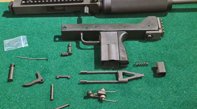
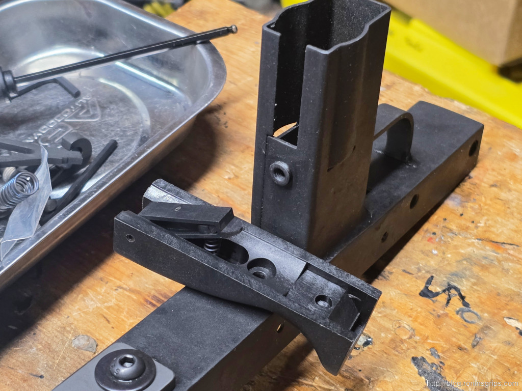
By this point I had welded my receivers, parkerized them and also prepped some old Israeli Sten magazines. It was time to assemble the Velocity Firearms MAC 9 firearms. Two would be registered as pistols and one as a rifle. They all use the same internals in the lower receivers so I bought complete internal lower parts kits from Velocity Firearms plus complete uppers from them as well. Note, the grip assembly with the mag catch is a separate part. I just bought it from them pre-assembled.
Parts Identification
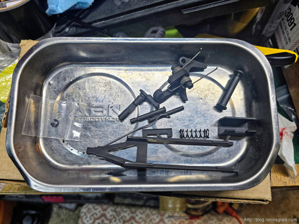
These are the lower parts for a Velocity Mac 9 (VMAC9):
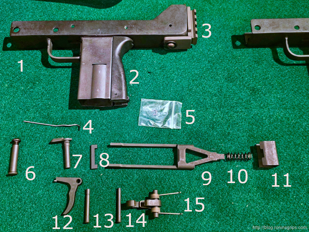
- Lower receiver / welded frame
- Back grip assembly – includes the Plastic back grip housing, mag catch, mag catch spring and mag catch pin
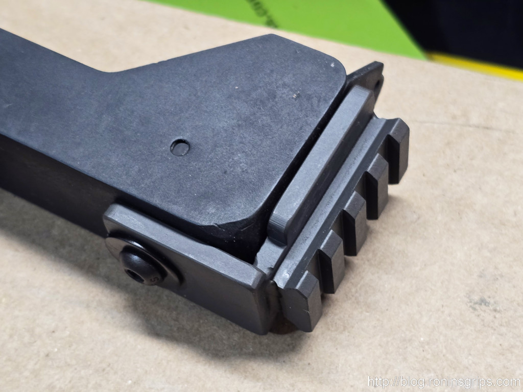
- Optional: This is a Practical Solutions rear 1913 adapter.
- Wire retainer for the selector lever and trigger pin
- Hammer pin retainer e-clip – it’s still in its bag so I wouldn’t lose it
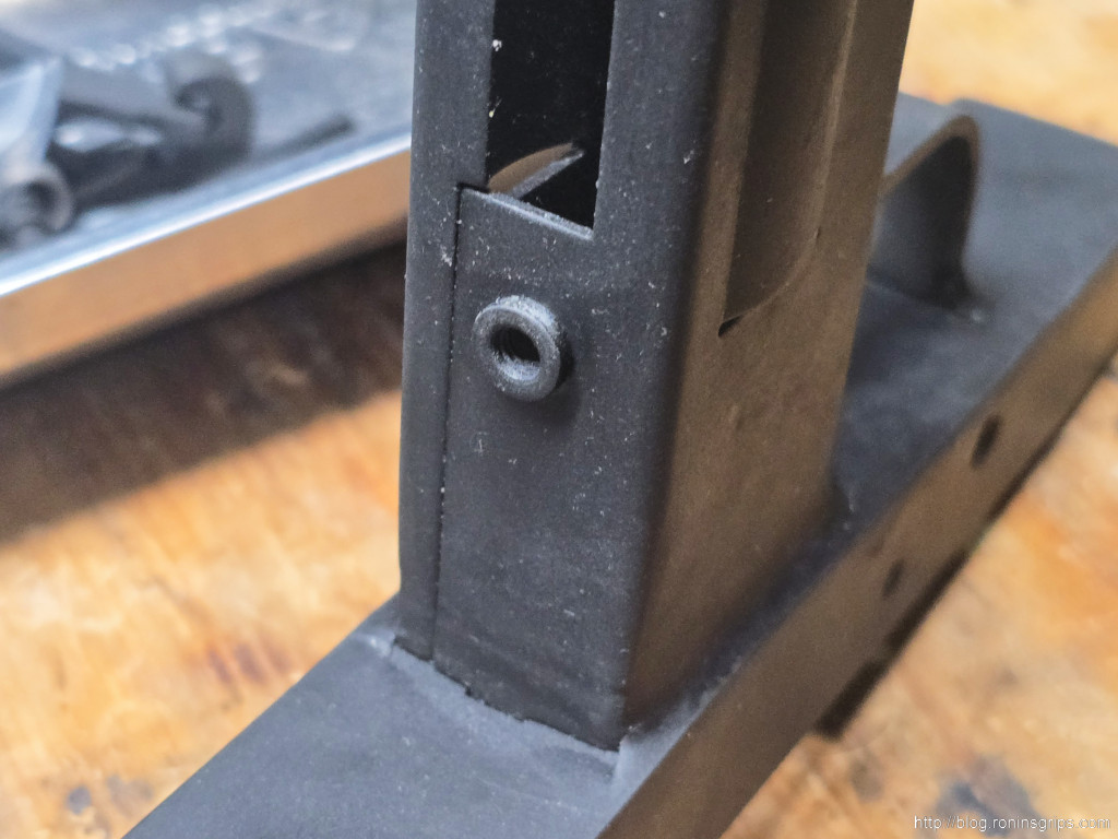
- Takedown pin assembly – tubular body and a hex socket button head screw.
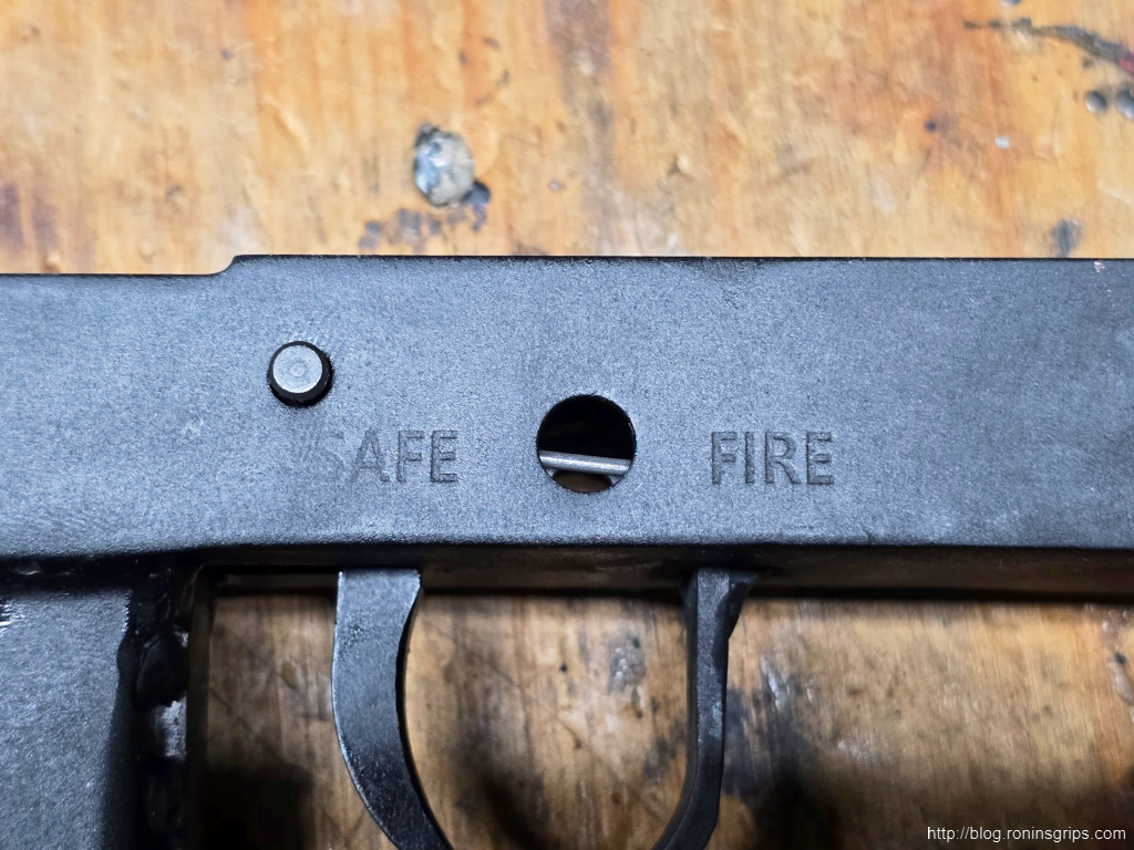
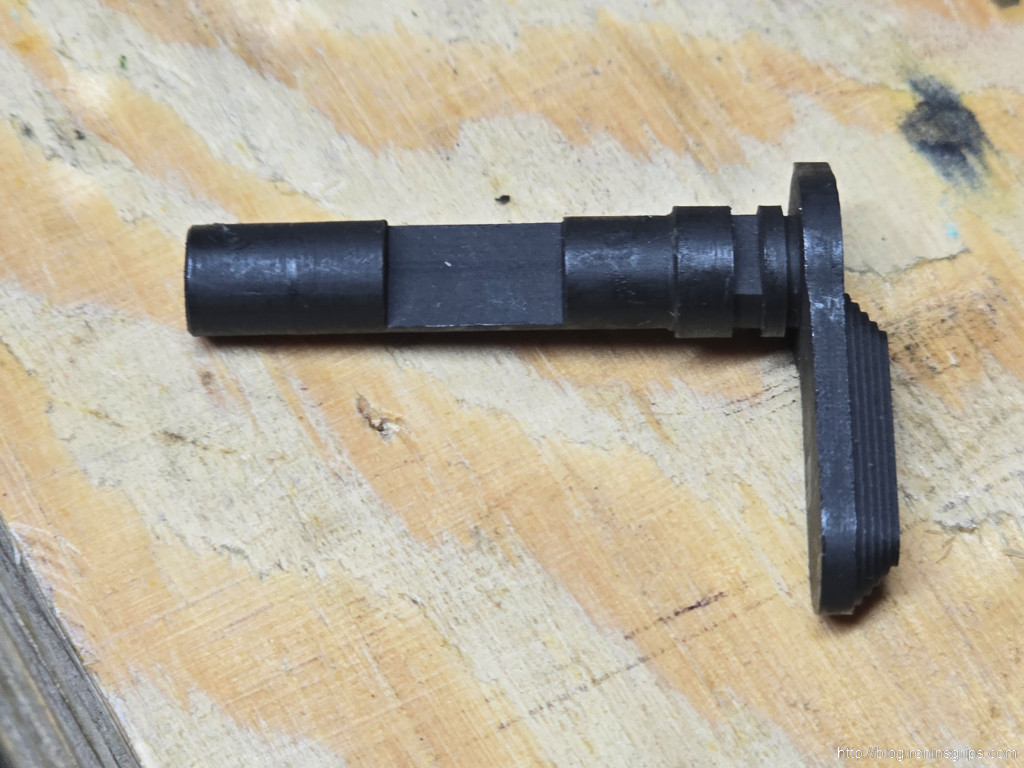
- Safety selector
- Trigger bar – note bevel goes face up
- Sear plate – This is positioned the right way – bevels go down, front slots to cradle the trigger bard are down.
- Sear spring
- Sear spring holder / spacer – bevel is at the top. This holds the upper in position
- Trigger
- Trigger pin – note the slot is set further back for the retainer wire
- Hammer pin – note slot is out at the end for the retainer e-clip
- This is both the hammer and the hammer spring – the spring is oriented properly. The hammer is resting striking face down.
The Practical Solutions 1913 Rear Rail Adapter
I knew I wanted a 1913 Picatiny rear rail for mounting braces or stocks to. I looked at a number and the Practical Solutions model received good reviews. I’ll tell you it is solidly made for sure.
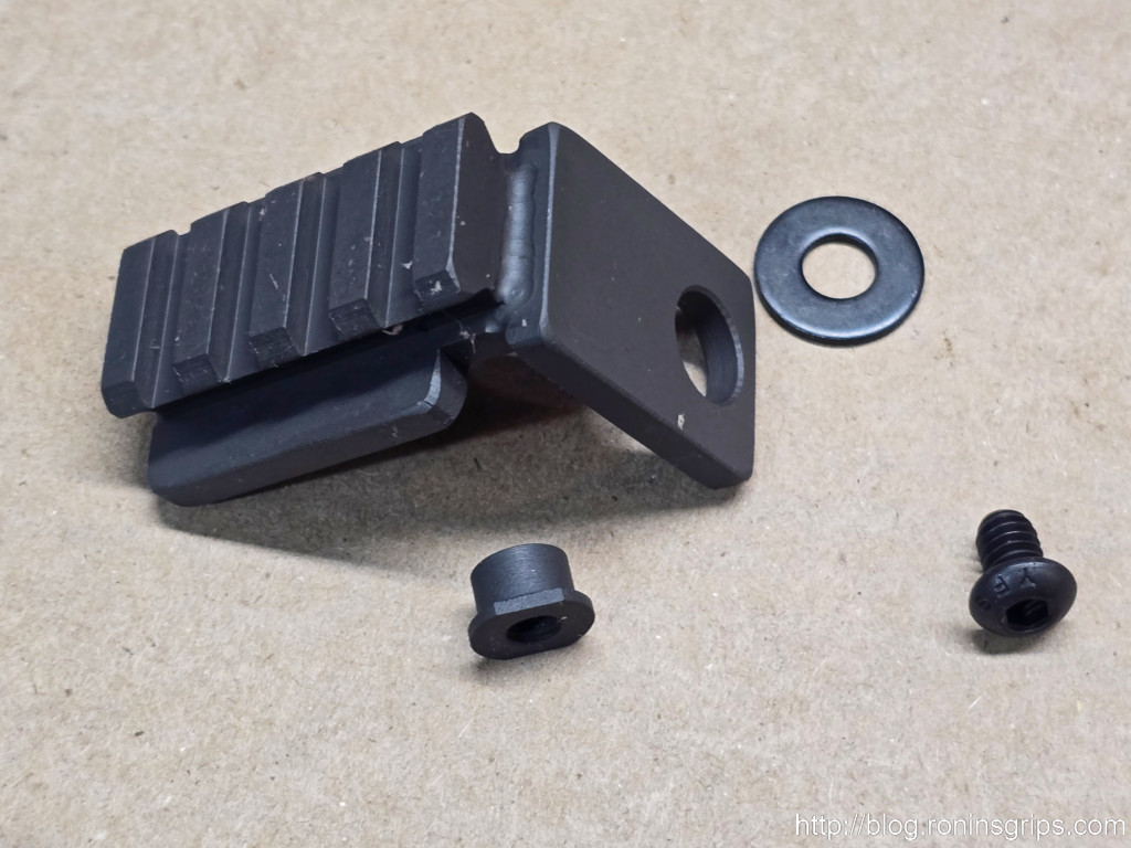
For the most part I like it because it’s easy to install. You will probably want to bed the adapter in the rear or else it will likely move. I mixed up some epoxy, black dye and 1/32″ glass fibers to make a putty that I then applied between the adapter and the rear of the receiver. Both parts had release agent on them just in case. I did this later because I didn’t realize how easily it could move with a brace or stock acting like a lever arm.
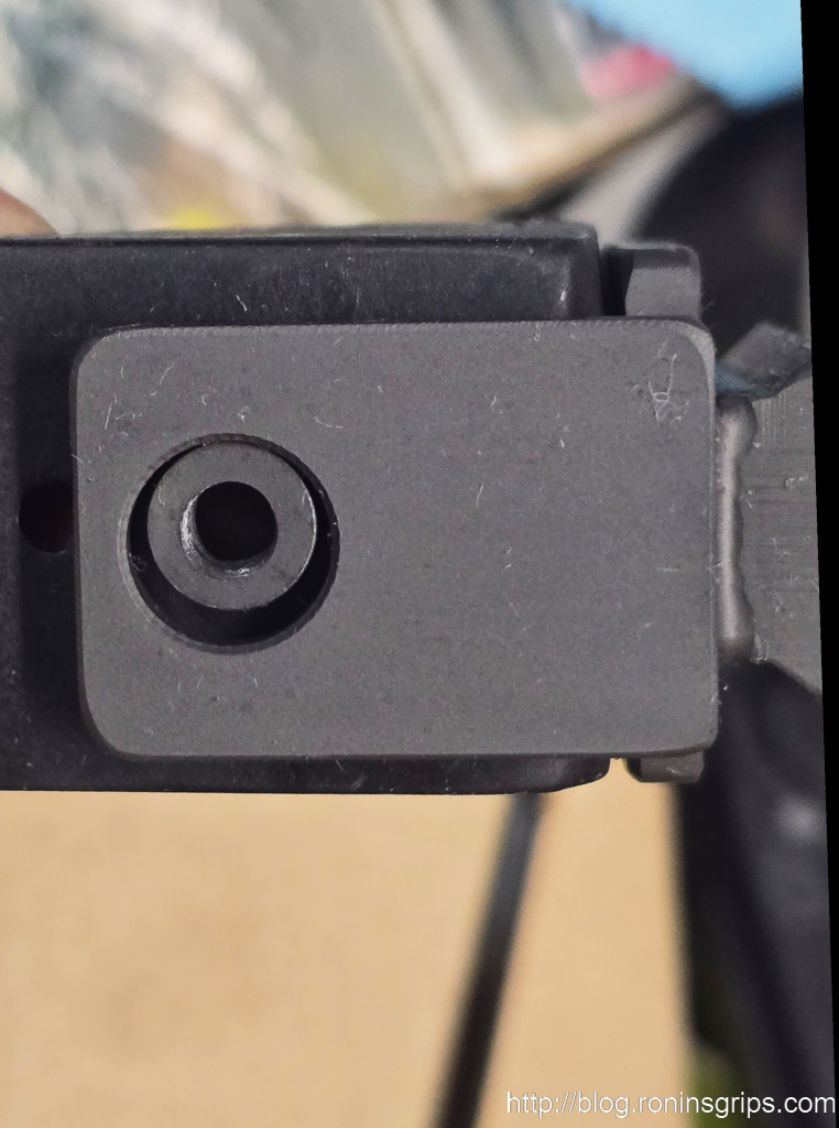
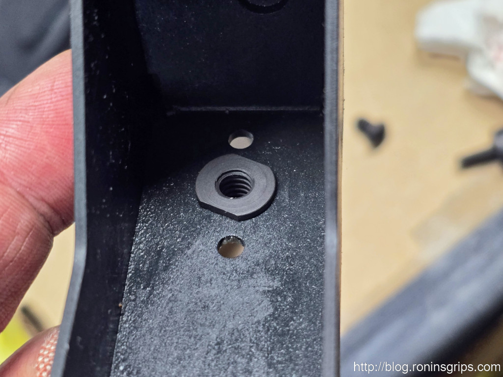
Also, the bushing will push the spacer up just a bit so you might want to grind/sand/cut a radius so the spacer can seat properly. Alternatively, just bend the spacer. I just bent the spacer until the upper would fit.
Let’s step through the assembly
- Install the plastic grip assembly taking care the mag catch’s half circle end sits outside of the mag well.
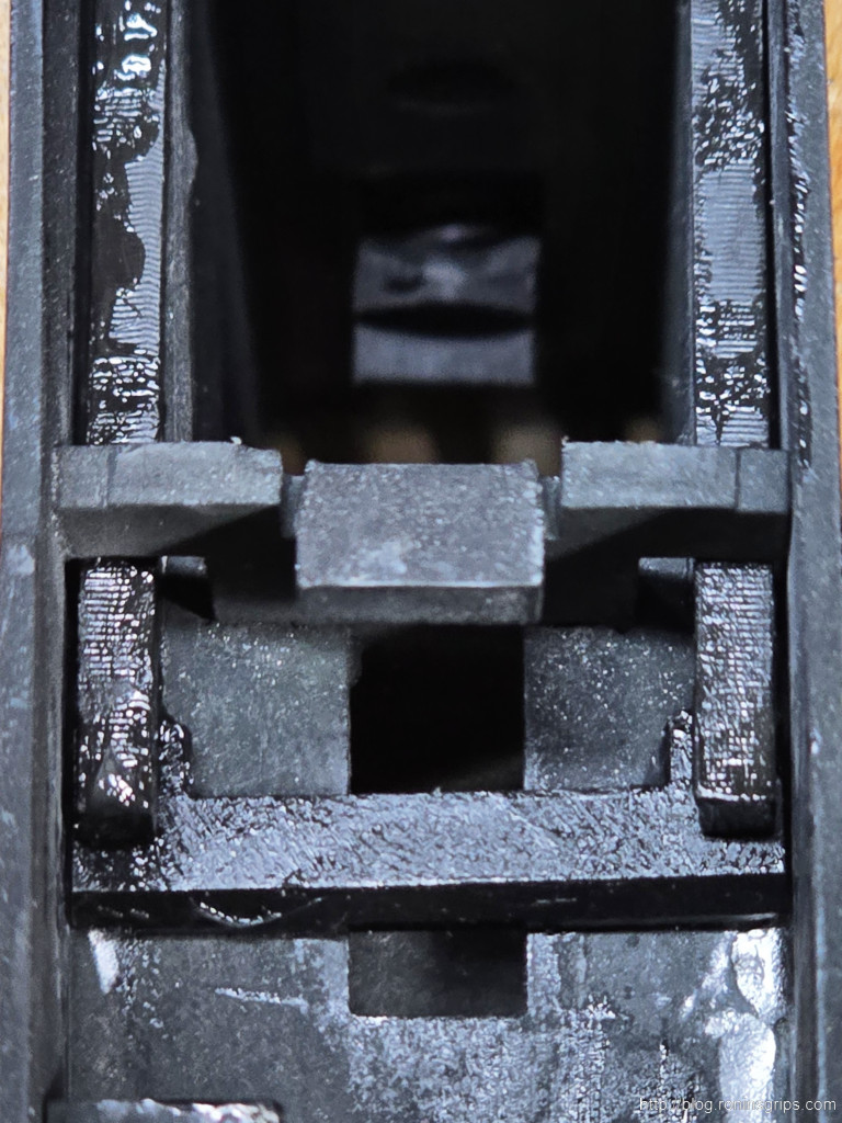
- Take the sear plate, tip the rear up and lower the front forks down so they slide under the bullet guide’s arms. The beveled front and rear rails are face down. Another way of thinking of the orientation is that the trigger bar slides under the front of the forks and sits in the machined opening. Make sure the sear plate can slide all the way forward to the center support and all the way to the rear. If there are any welds in the way, grind them so everything slides smoothly.
- At this point, I start lubricating as I go. If it slides, grease it. If it rotates, oil it. I use SuperLube grease applied with an acid brush to all surfaces that need greasing. Oiling was done with SuperLube oil. I like the two as they are synthetic and don’t get gummy plus they have PTFE (the generic acronym for Teflon) added to improve lubricity. The coarse parkerized surfaces will want to slow everything down while they wear in.
- Slide the sear plate forward, install the spacer to the rear with the beveled face up. Try test installing an upper at this point. You may need to squish the spacer a tad in a vice to allow the upper to seat easily.
- Slide the sear plate spring onto the sear and move the sear to the rear so it is all inside the sear spring holder / spacer.
- Insert the trigger bar with the beveled face up. I used needle nose pliers to do this and slid it under the front of the sear plate.
- Move the whole trigger bar and sear plate rearward so you can drop the trigger into the hole in the receiver and also such that the trigger is in front of the trigger bar.
- Insert the trigger pin from left to right. This requires a little bit of manipulation to get the pin through both sides.
- Install the hammer spring it it hasn’t been already. It should be oriented the way you see above.
- Install the hammer in the rear. It sits like an AR hammer with the flat face forward. The spring legs rest between the sear plate’s legs.
- Install the hammer pin
- Put a daub of grease on the receiver around the hammer pin. This is an old trick and will hold the e-clip in position while you slide it on. I’d recommend using something non-marring to push the e-clip on and you’ll feel the cip snap into position. Another trick is to lower the pin such that the slot is even with the receiver so you don’t have to try and get the clip at the right height while fighting everything else.
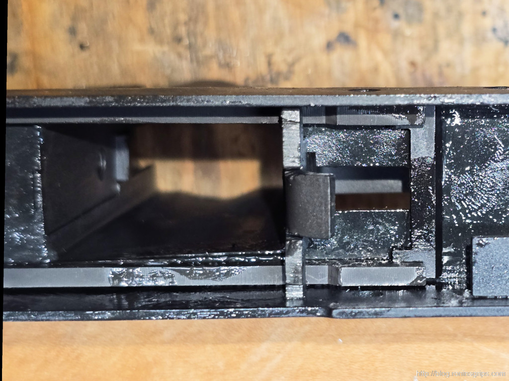
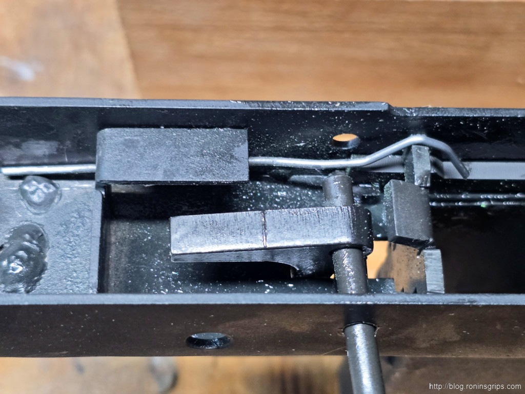
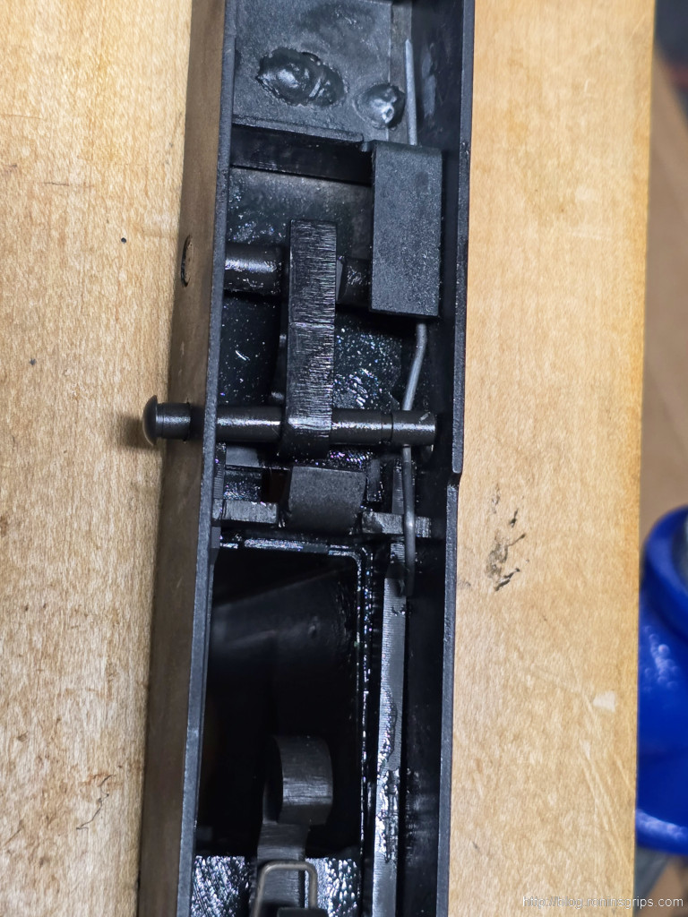
- Install the retaining wire by sliding the forward portion under the front reinforcement. The hooked portion sits in the groove on the right “ear” of the bullet guide. I’ll show photos below.
- Technically, you are supposed to lift the retaining wire up and insert the selector under the wire. This is what adds the tension to lock the selector and trigger pins in place. Uhm .. there was no way I could do that. If you can get it together/ go for it. I was getting pissed off and needed to think of a different approach. So, if you were able to lift the wire up and install the safety selector lever then you are done with the lower. Speaking for myself, I had to add the following:
- For the life of me, I could not get the selector lever in due to an elevated area on the inside and I couldn’t get the wire any higher. Instead, I backed off the trigger pin and inserted the selector because the tension was gone. The issue then became how to get the trigger pin in. What I did was to align the pin on the hole and used a grooved screwdriver (spanner bit) to forcefully push the pin and retaining wire down facing the hole while pushing from the other side so the pin would pop into the hole. That worked. One reason it worked was that I could see what I was doing and how to move things whereas with the selector lever and wire, I couldn’t see what was going on.
- Note, you will need to help the sear plate and hammer to go into the cocked position before you install the upper.
- I did a quick function test while controlling the hammer so it wouldn’t smack into things. Pulling the hammer back, the sear plate would grab it. Pulling the trigger back, the sear plate would release the hammer – again, I caught it vs. letting it fly free. I squeeze the trigger back, moved the hammer back, let go of the hammer while the trigger was squeezed and the sear plate grabbed it. I pulled the trigger and the hammer “fired”. I then made sure the safety worked. Everything was good.
Now For Photos
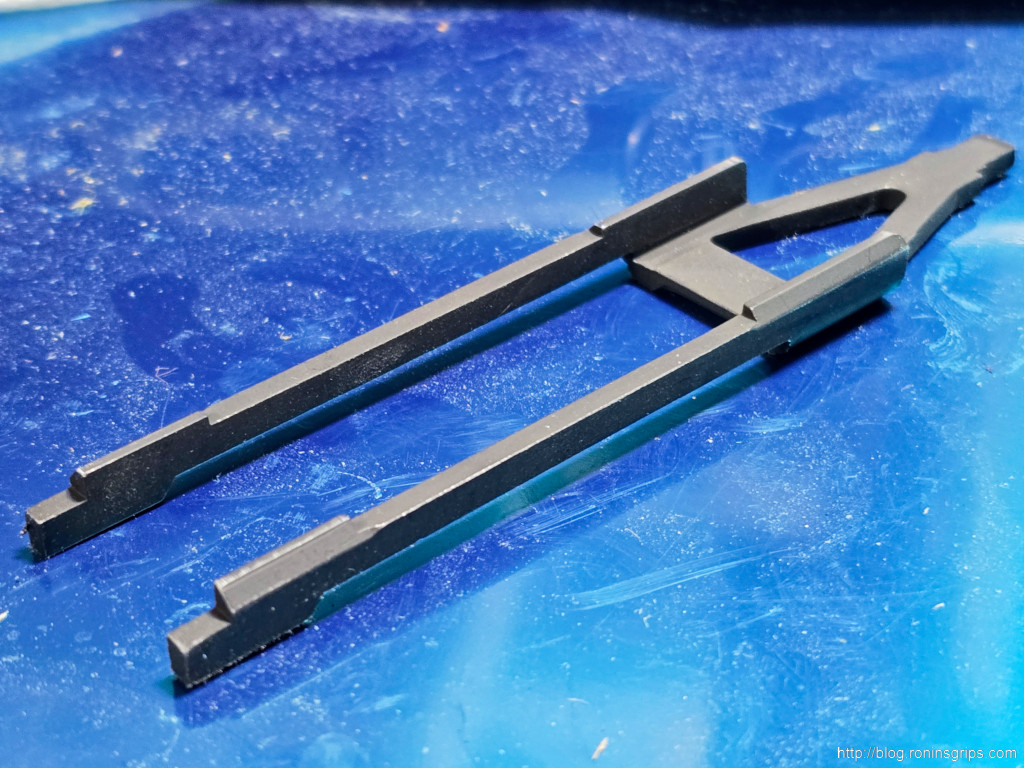
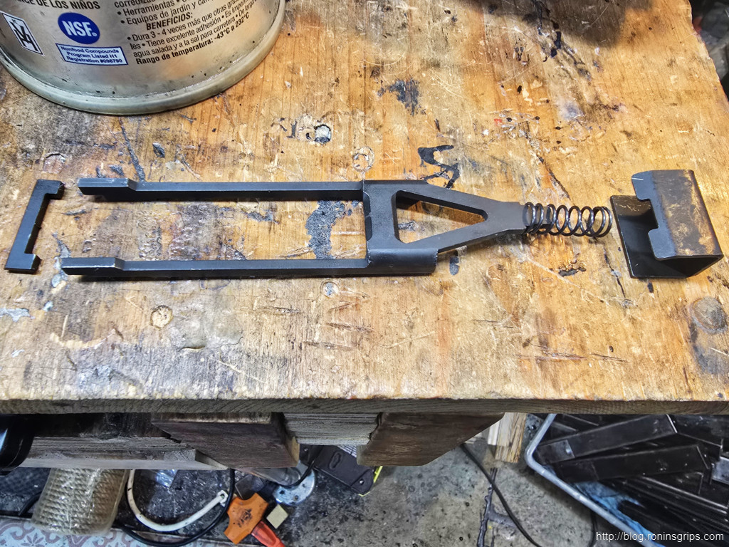
I don’t have a photo but make sure the sear place and trigger bar can slide unobstructed. If there are welds or anything in the way, grind them out, then blow out the receiver before you coat everything in grease.
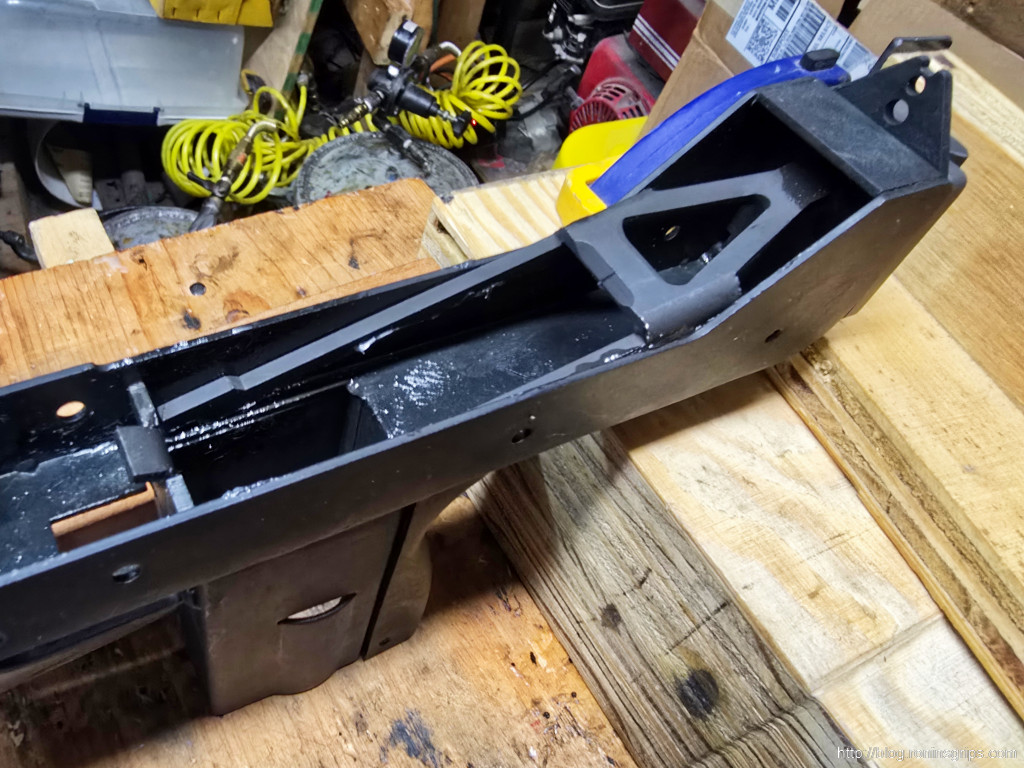
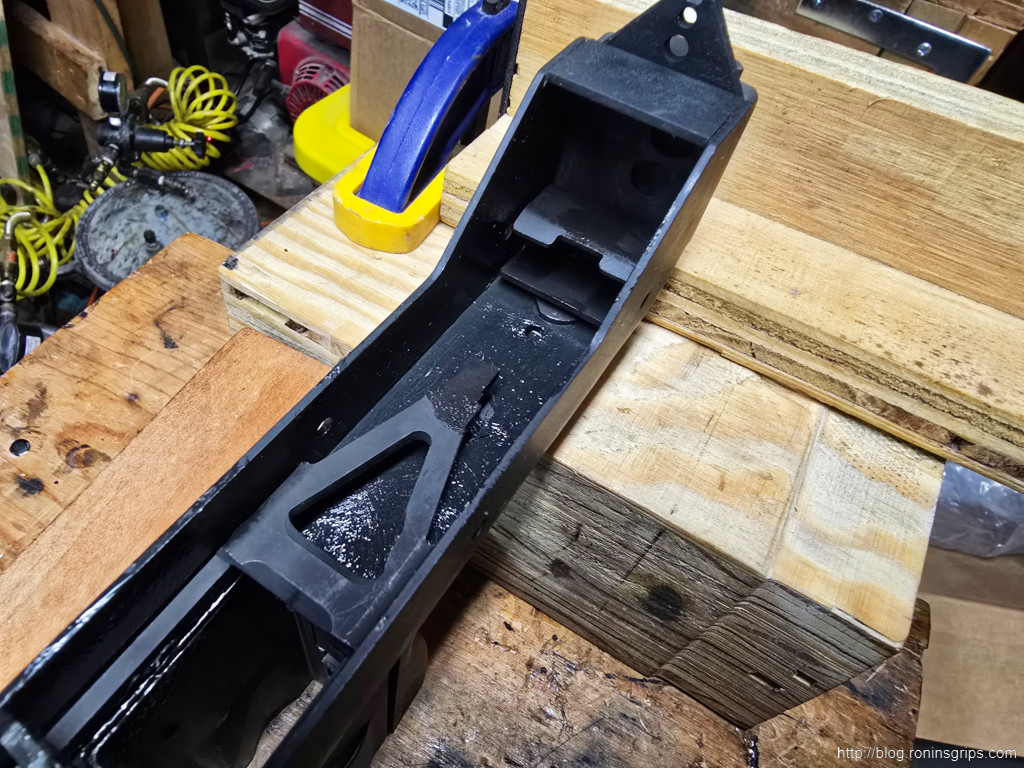
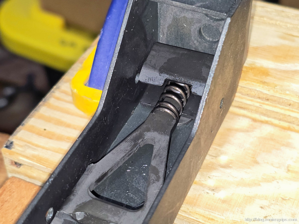
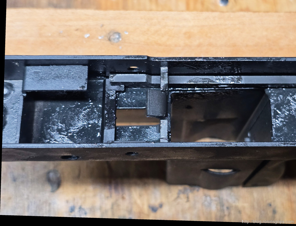
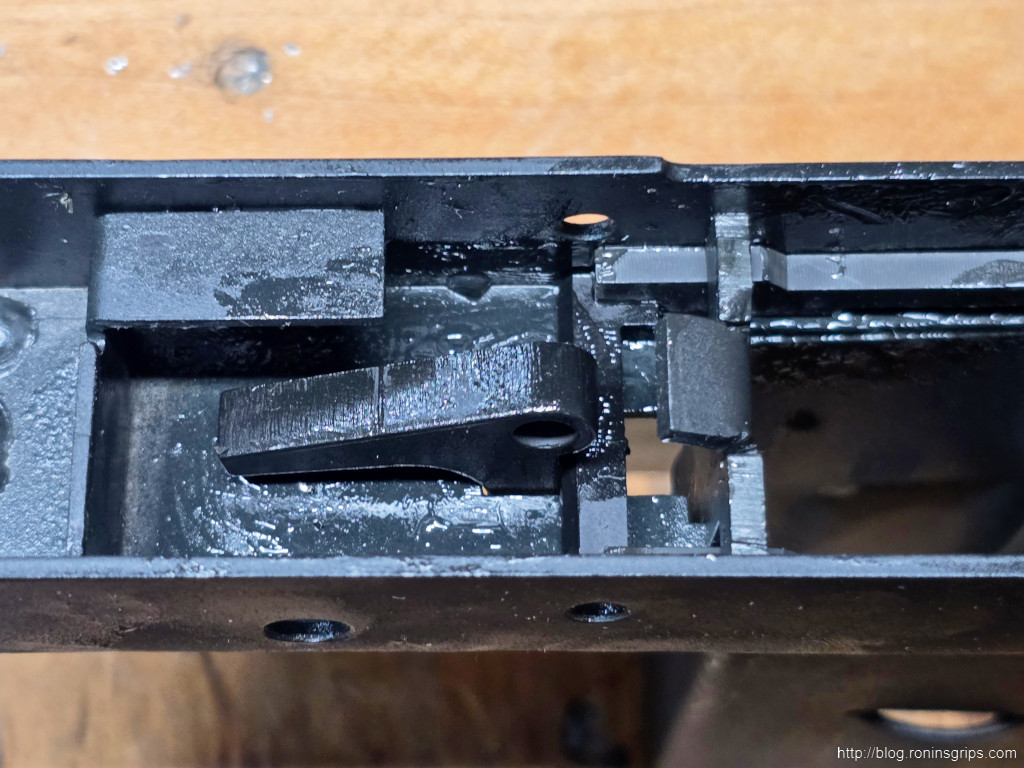
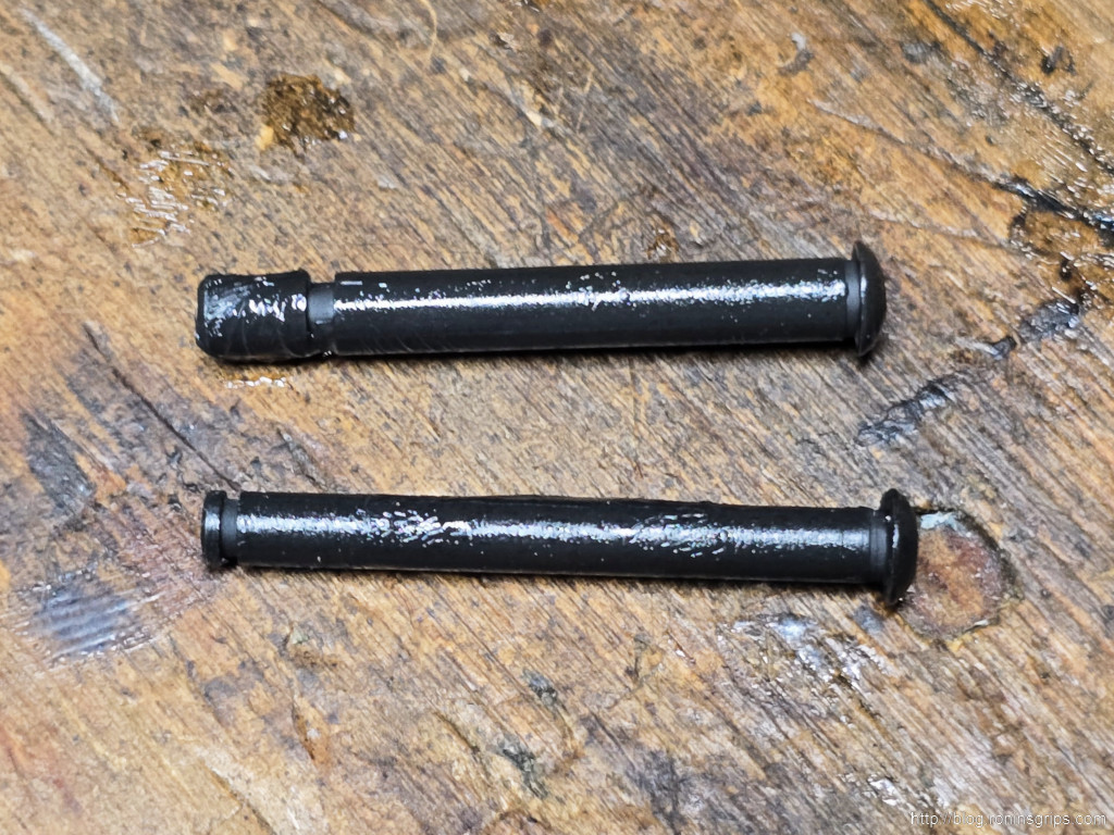
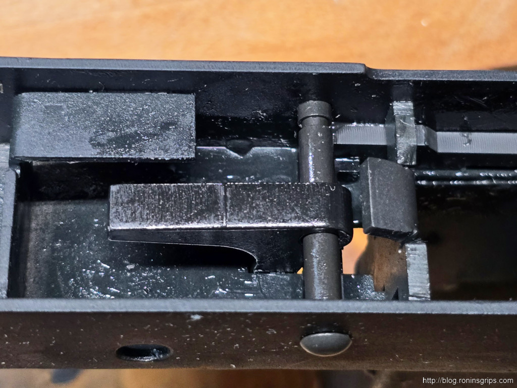
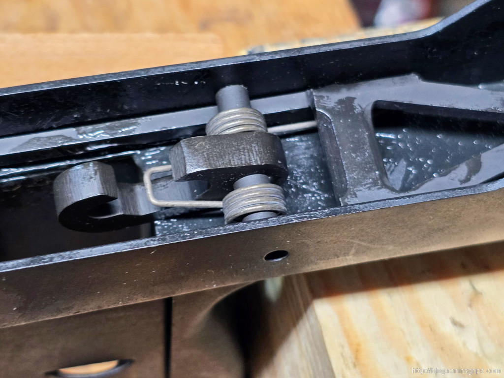
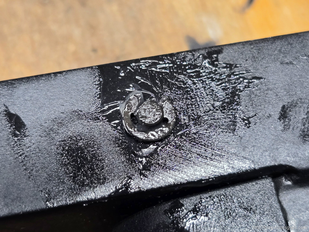
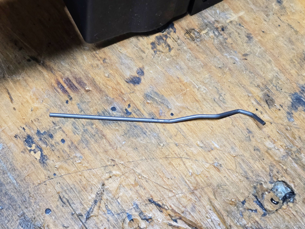
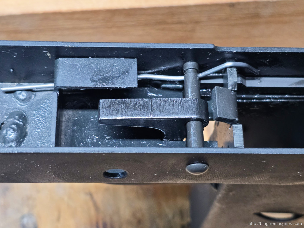
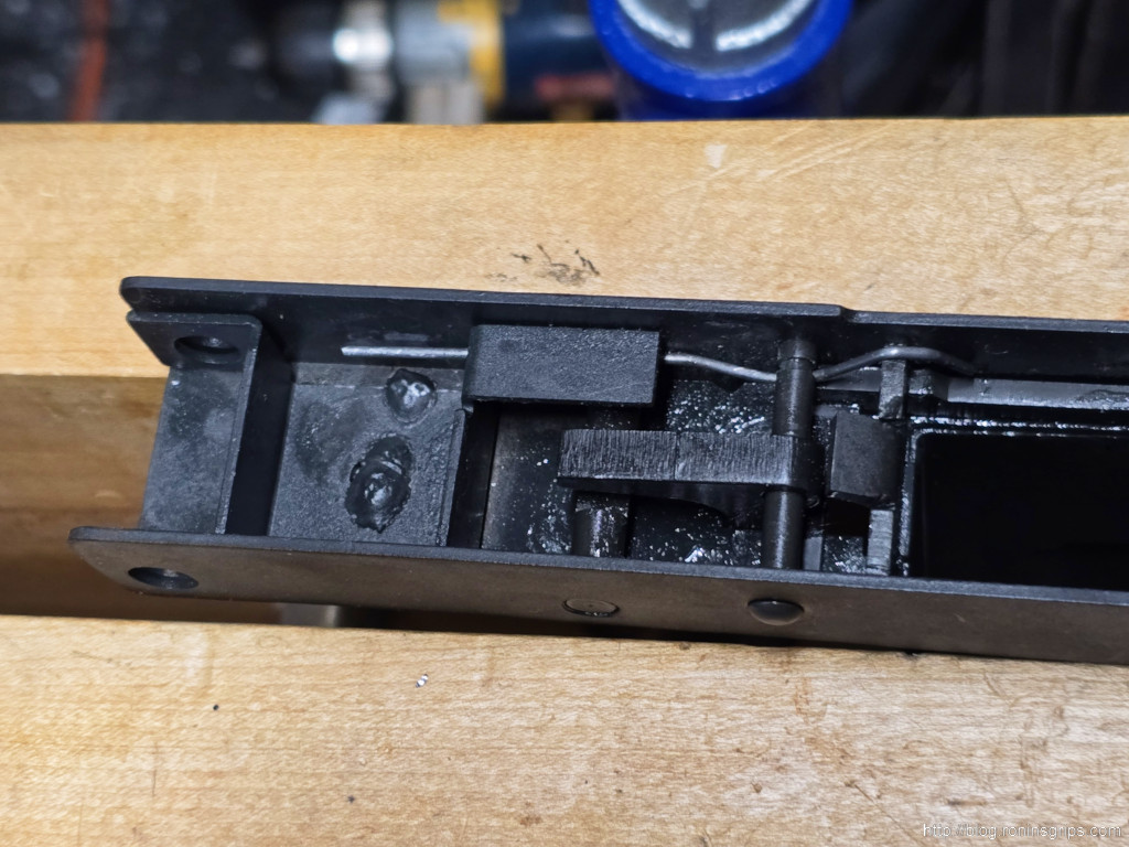
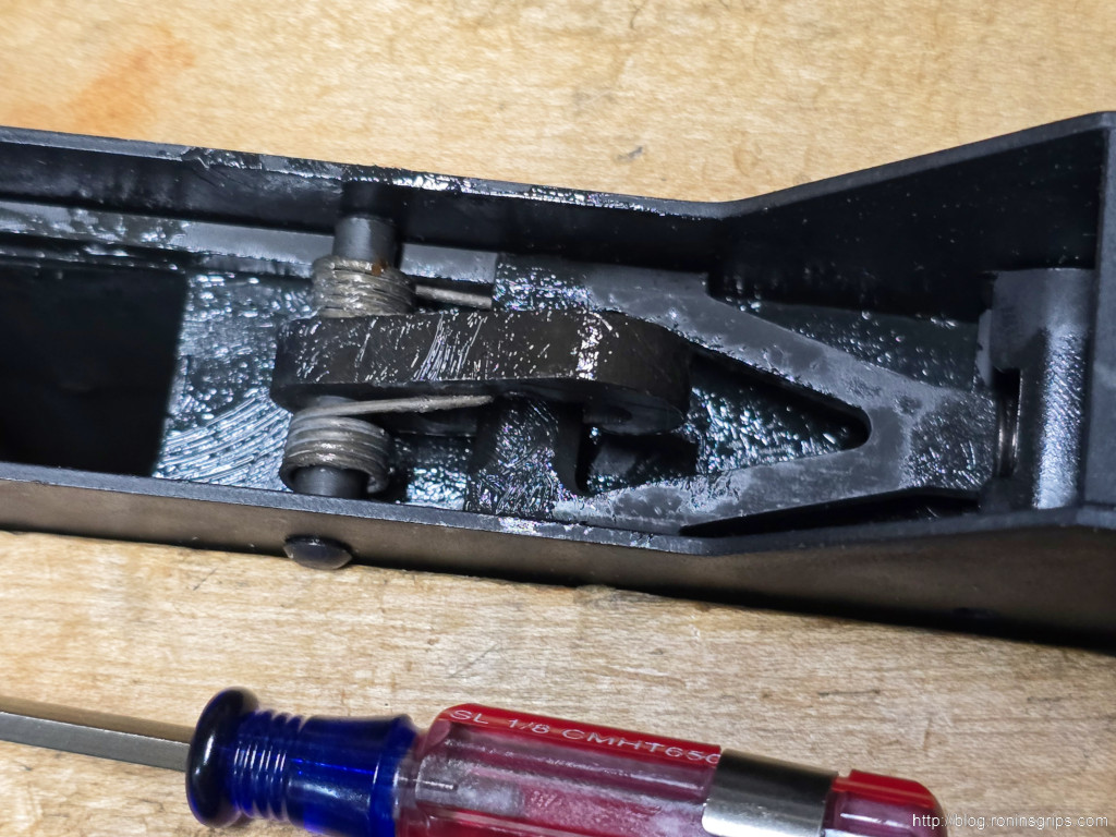
Be sure to do the function testing outlined above. All weapons should be cautiously test fired to ensure safety.
Summary
I was actually impressed by the design other than my extreme dislike for the retaining wire. The trigger is better than I expected. Not great but not horrible either.
In the next post, I’ll take about the first upper and how I configured the firearm.
I hope this helps you out.
Note, I have to buy all of my parts – nothing here was paid for by sponsors, etc. I do make a small amount if you click on an ad and buy something but that is it. You’re getting my real opinion on stuff.
If you find this post useful, please share the link on Facebook, with your friends, etc. Your support is much appreciated and if you have any feedback, please email me at in**@*********ps.com. Please note that for links to other websites, I may be paid via an affiliate program such as Avantlink, Impact, Amazon and eBay.
