Tag Archives: Install

Assembling an AR Lower – Step 10 of 11: Installing the Upper Receiver Assembly

We’re in the home stretch.  You can buy completed AR uppers from many sources.  I’ve had very good luck with Palmetto State Armory (PSA), Ghost Rifles, White Oak Armory (for precision uppers), Del-Ton, and Rock River Arms.  I bought a few Hardened Arms uppers with bolts and simply was not impressed – they seemed gritty and with a 12.7×42 Beowulf build their bolt did not work correctly but I digress.

With that said, the short barreled upper with the Magpul furniture is from PSA and the 10.5″ upper is from Ghost Rifles.  If you were to ask me who I use the most, I’d have to say PSA.  Subscribe to their Daily Deals email list and you’ll see some pretty wicked deals.  With all of the uppers, take note if they are selling the complete upper with the bolt carrier group (BCG) and charging handle or a stripper upper that does not include those two things.  I buy depending on what I want to do.  For both of these pistols, I bought stripper uppers as I had PSA Nickel Boron (NiB) BCGs that I got a deal on in the past plus I planned to use a PSA charging handle that I had with an extended latch and already had a plain Mil-Spec charging handle that I could use though I do have one of my favorite charging handles – the BCM Mod.3 large latch model – on order.

The next photo shows the two uppers side by side.  The PSA upper had the 7″ barrel, CAK Flash Can, Magpul handguards, gas block, tube, and ejection port dust cover installed – all it needed was the BCG and charging handle.  The Ghost Rifles upper had the 10.5″ barrel, handguard that I had to trim down for the look I wanted, and ejection port dust cover installed.  I added the brake, BCG, charging handles.  The side rails on both uppers are M-Lok and were added by me along with the backup sights.

Now when planning an upper, as long as it is Mil-Spec, and they all claim to be, it should mate (a fancy way of saying “fit”) with your Mil-Spec lower.  What I have found over the years is that some brands go together nice and snug and some are looser.  For example, PSA uppers fit Anderson lowers nice and snug.  The Ghost upper was a tad loose on the Anderson lower so I added a spacer to tighten it up.

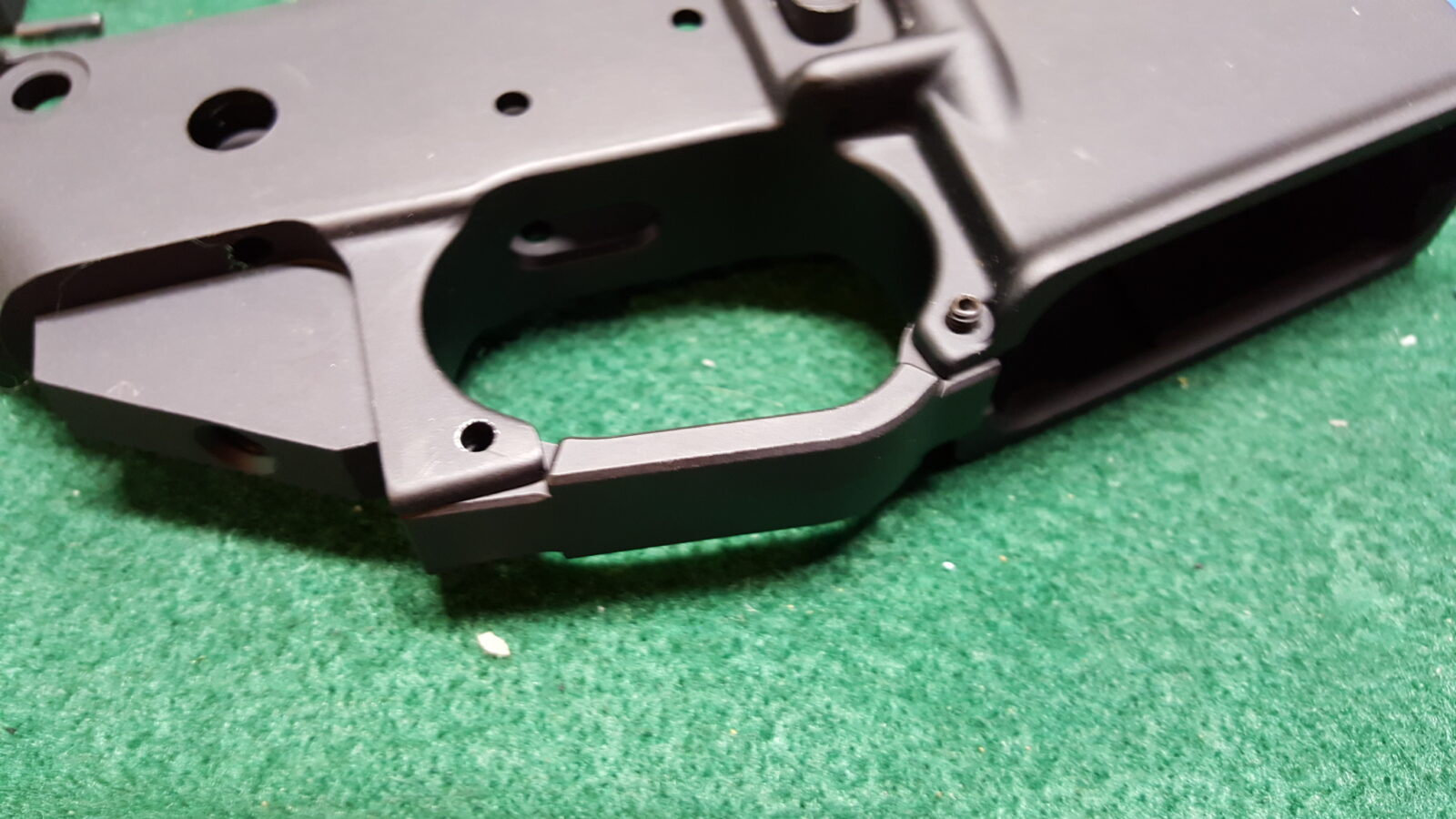
Okay, so here is how it goes.  First, open both pins on the lower like so.  Note, you see the buffer already installed.  I took an assembled pistol and removed the upper to take the photos.  Of course, when I am writing this blog post then I notice I forgot to remove the buffer purely for the photos.  Just imagine it is not there 🙂  If it is, no worries – the pins work regardless.  The pins and modular design is what makes the AR like Legos for shooters – you can open them and swap uppers at the drop of a hat.

Step two:  Inspect the bolt and make sure the gas key screws are staked, that the bolt head can move freely, the extractor works, firing pin present, etc.  Normally I do not take the bolt apart – just a quick double check.  I have only had challenges with no-name bolts.  PSA, Aim, and Fail Zero. have all worked just fine for me.  The Fail Zero BCG is very well made if you ever get a chance to use one.  If the BCG feels or looks funny then a closer inspection is warranted but outside of the scope of this post.  Both of the pistols I assembled in this post is a PSA Nickel Boron (NiB) BCG.

Step three:  I like to install the BCG and charging handle before I put the upper on the rifle.  You can install the upper and these items if you want.  First, I oil the lubrication points of the BCG and apply grease to the underside of the BCG.  Do NOT put a ton of grease or oil under the handle.  I just put a very light coat of oil on the whole body of the handle.  You do not want to get a ton of grease on the gas system.

Step Four:  The charging handle has little tabs towards the front.  Slide the charging handle in above where it resides, align the tabs on the handle with the keyway in the receiver and press the handle down to where it normally goes.  Do not slide the charging handle in yet because the BCG slides in next.

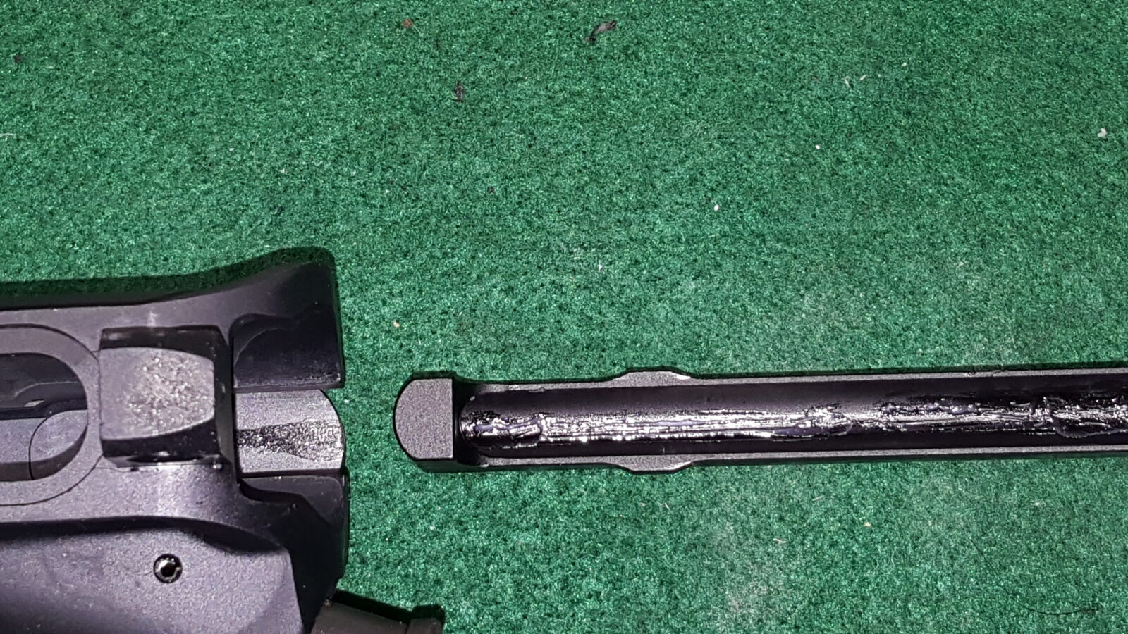
Step Five:  Ensure the bolt head is pulled all the way out.  You then put the top of the bolt in the handle and slide the assembly forward until the handle locks into position.

Step 6:  Put the buffer in the buffer spring and slide it into the buffer tube spring first.  When you get to the buffer itself, you may need to push the buffer detent down a bit to get it to slide in.  I like the slightly heavier H2 buffers and used a PSA and a Spikes in these two builds.

Step 7:  Line the front upper hole with the lower and close the pivot pin all the way.

Step 8:  Swing the upper down and close the rear takedown pin.

Step 9:  Technically you are done – the two halves are assembled and you can function test your FCG.  [For a review on function testing the FCG, click here.]  At this point, I do what I call a “rattle test”.  If I shake the rifle and the upper is loose in the lower, I add a rubber receiver wedge (these things have a ton of names) to remove the slop.  Basically it sits in the lower and you trim the bottom of it until you can close the upper but there is upwards pressure from the wedge locking everything in place thus removing any play.

And with that, you are done with the basic assembly and can go ahead and add whatever accessories you want.  When you are planning what to do – ask yourself “Is this a range toy or something I need to rely on and if so, what are key considerations?” and use that to govern what you add.  For example, on a defensive weapon, I have backup sights, a quality Vortex optic and a quality Streamlight weapons light.  I do not go with cheap stuff as I have had them fail on me.  For a range toy, I worry a lot less about what reliability for example.

So here are the two finished pistols.  The 7″ is a range toy and the 10.5″ may well serve a defensive purpose so it has a Vortex Spitfire red dot and backup sights.

Okay – safety briefing time:  When you test fire, consider using a stand and pulling the trigger with a string from a safe distance.  Be sure to inspect the weapon carefully before and after.   If you do not feel comfortable with any of this, please see a gunsmith.  If you have any doubts at all, please see a gunsmith.  I want you to enjoy assembling your AR and shooting it.

By the way, my AR expert is Scott Igert of Modern Antique Firearms.  He is a police officer and has years and years of real world AR building, maintenance and tactical use experience.  If you need a custom AR built, need to buy parts, or have gunsmithing done, talk to Scott.

Hope this series helped you out!  The next post, step 11, will provide additional resource information.

Sources For AR Parts

The following are all vendors of AR parts including barrels, handguards, triggers, magaziness and what have you that I use and recommend:

Beware no-name knock off websites selling generic import stuff. Some of the parts are counterfeit and not rated for firearms use.


If you find this post useful, please share the link on Facebook, with your friends, etc. Your support is much appreciated and if you have any feedback, please email me at in**@ro*********.com. Please note that for links to other websites, I may be paid via an affiliate program such as Avantlink, Impact, Amazon and eBay.


Assembling an AR Lower – Step 2 of 11: Installing the Trigger Guard Assembly

The second step is to install the trigger guard.  Now I do not use the kind with a detent that allows you to open the trigger guard.  I prefer aluminum trigger guards from either Magpul or Brownells.  The one you see here is from Brownells and is made from billet 7075 aluminum.  I like how it is slightly oversized for gloves and Brownells prices it quite reasonably at $8.47. The front is threaded with a set screw and the rear has a roll pin – they include both in the package.  A polymer Magpul unit came with the lower build kit and I just put it in my box of spare parts.

Take a minute and check the fit.  The threaded part goes forward and the hole that goes all the way through to the rear.   Just ensure it is going to line up appropriately.

I like to first install the front set screw to help line everything up.  Just use a quality allen wrench – I have been burned with cheap allen wrenches that round the socket so now I pretty much stick with Bondhus and Eklind though there are probably many other good enough brands out there.  I snug the set screw down but do not go crazy torquing it in.  Bear in mind you are threading a small screw into aluminum and that allen key is giving you quite a bit of leverage.

Once that front screw is in and the trigger guard is better held in position, it is time to install the rear roll pin.  Now you have a number of options to install the rear pin and I am going to tell you about the two I use:

Option one, use a starter and roll pin punch to drive in the roll pin.  Now there is a real important thing you need to do – be sure you use a block to support the lower “ear” of the receiver or you may snap it off.  If it breaks off, you just ruined the receiver – game over.  I use a Wheeler block to support the receiver and you can use just about anything – over the years I have used generic gunsmithing blocks and even pieces of wood. For the last 2-3 years I’ve used the Wheeler block and like it.

Don’t try to use a generic punch.  I like to use a Squirrel Daddy roll pin starter to get the first part of the pin installed and then an Astro Pneumatics 1/8″ roll pin punch to hammer it in the rest of the way.  Of course you can use whatever brands you want but the bottom line is that you need to line the pin up vertically to drive it straight in and you must be careful not to slip and mar your receiver.  This is why using the correct punches matter.  The starter punch gives you a lot of control and by using the roll pin punch, you can keep your punch on the pin.  Because of my tremor, I am not very good with hammers and punches but can do this provided I use the two types of punches mentioned.

The Wheeler 156945 bench block does a good job helping you both hold and support work.  You want the “ears” on the receiver to be supported.  There are plenty of stories of guys not supporting the ears, trying to tap in the roll pin that holds the trigger guard in place and then breaking off an ear.  Whether you use the Wheeler block or even a piece of wood – be sure to support the ears.

Note how nicely the Wheeler 156945 bench block supports the AR lower.
This is a roll pin starter punch. This one is made by Squirrel Daddy.

Option two:  Wheeler Engineering makes a nice simple tool to install or remove that roll pin.  Boy does it make it easy and this is my preferred method.  The little tool is super simple – it has two pins that fit into the end of the screw.  A long one for removing the pin and a short one for installing the roll pin.  You just line things up and then tighten the screw.  The pin goes into the hole in a very controlled manner and your finish is protected.  Stop once your pin is flush with the receiver.

Other options:  I have seen guys use pliers with the jaws wrapped in tape, modified C-clamps, and more.  You can Google around or search on Youtube to see a variety of approaches.


If you find this post useful, please share the link on Facebook, with your friends, etc. Your support is much appreciated and if you have any feedback, please email me at in**@ro*********.com. Please note that for links to other websites, I may be paid via an affiliate program such as Avantlink, Impact, Amazon and eBay.


AR Parts Sources

There are a lot of reputable AR parts vendors online but beware of eBay and bargain basement dealers that sell airsoft parts and tell you they will stand up to firearm use – they will not. At any rate, here are my top sources of AR parts:


How To Install Ronin’s Grips’ Vepr Furniture Set

Ronin’s Grips Vepr Furniture Installation Notes

Version 1.7  1/27/2014

First and foremost, please ensure your rifle is unloaded and a round is not in the chamber.  Please be safe!

In general, the urethane plastic we use for the buttstock and handguard will behave like hardwood when it is being cut.  Thus, if you choose to install something, follow the guidance for a wood stock in terms of hole sizes to drill, tools to use, etc.  Note, the plastic has very little give and forcing parts together will risk stress fractures.  Make sure they seat/fit in a square even manner.

The following are installation notes for each component of our Vepr rifle furniture system.  What you need to install will depend on what you purchased.

Buttstock

The buttstock is attached to the rifle’s rear trunnion via two #10×7/8” screws.  The urethane plastic we use is very hard and ideally the hole for the screw should be drilled with a #21 (0.1590”) drill.  Take care to ensure the stock is centered before locating and drilling each hole.

Tip:  If for some reason you need to drill a new hole, the old hole can be filled with quality epoxy cement and allowed to cure per the instructions of the glue. To fill a deep hole, either run the epoxy down the side or use something long and thin, such as a toothpick, to get the epoxy to the bottom.

For durability, use a longer setting high-strength epoxy as the quick 90-second, 5-minute and 10-minute epoxies are prone to “sugaring” or breaking down with constant jarring.  JB Quickweld, Brownell’s Acraglas (our recommendation) and DevCon industrial epoxies (such as “Plastic Steel”) are all good choices.  If you want to color the epoxy black, add a bit of black powdered tempera paint to the mix while stirring thoroughly.

Please note that if you buy the buttstock without a recoil pad, you must add one to protect the end of the stock from abrasion.

Optional Recoil Pad

The recoil pad is secured to the rear of the buttstock via two #10×3/4” screws.  Again, be sure to drill a hole first with the recoil pad centered on the stock.

If you want to blend the pad to the stock, put a thin film of black RTV silicone on the buttstock and use your finger to smooth the edge between the stock and the pad.  This is for looks only – the screws must still be used to secure the pad in place.  If you decide to do this, fit the pad first and have everything ready.  Then remove the pad, add the thin amount of RTV, put the pad back on, tighten the screws and then blend the silicone with your finger.

Handguard

There are two key things you need to know about the handguard:

First off, there is a special 13mm wide x 5mm thick spacer in the bag with the screws.  It must be used between the handguard and the barrel lug to get the angle correct.  The original Vepr screw is used and the special spacer is mandatory.  If you lose the spacer at some point down the road, stack 6mm washers from the hardware store to get the necessary space between the barrel and the handguard.

Second, with the spacer on the screw, swing the handguard into place but do not tighten the screw.  The Vepr handguard sometimes fits tightly and you don’t want to adjust the screw hole if the unit isn’t fully seated at the rear in the receiver.  Carefully remove the screw, leaving the spacer properly positioned and look down in the hole and check the alignment between with the screw hole in the forearm and the hole in the barrel lug.  You may need to use a circular file to carefully “slot” the handguard hole just a bit to get proper alignment.   It is very important that you make sure the handguard is fully seated to the rear before you make any changes. Take a little off and test over and over– go slow and don’t rush.  Use the oblong washer that came with the stock to reinforce the hole.  If the handguard does not rest squarely against the receiver you will risk the handguard cracking by the barrel lug as it will be placed under undue stress during firing.  So, take your time slot the hole as needed.

Care of the Handguard and Buttstock

The handguard and buttstock are made from our proprietary urethane plastic that is machinable.  This means you can drill, cut, sand, abrasive blast and so forth.  When we build the furniture, we sand to 180 grit and then use 80 grit AlOx blast media at 90 PSI to frost the plastic.

If something chips or gets scratched at some point in the future, sand with 80 grit, then 100-150, then 220, then 320 then 400.  Another option is to repair the scratched area and then abrasive blast after 150-180 grit sand paper is used.  When making the furniture, we use an abrasive blaster with 80 grit aluminum oxide media at 90-100PSI to create a non-slip surface.  After either sanding or blasting, you can apply a wax based finish as a “top coat”.  The recommended sealer is actually a beeswax blend developed for boots called “Sno-Seal” by ATSKO.  In general, you could use any wax based finish such as clear or black shoe polish, that is then buffed with a cloth.


Thank you for purchasing our furniture.  We truly hope you enjoy it.