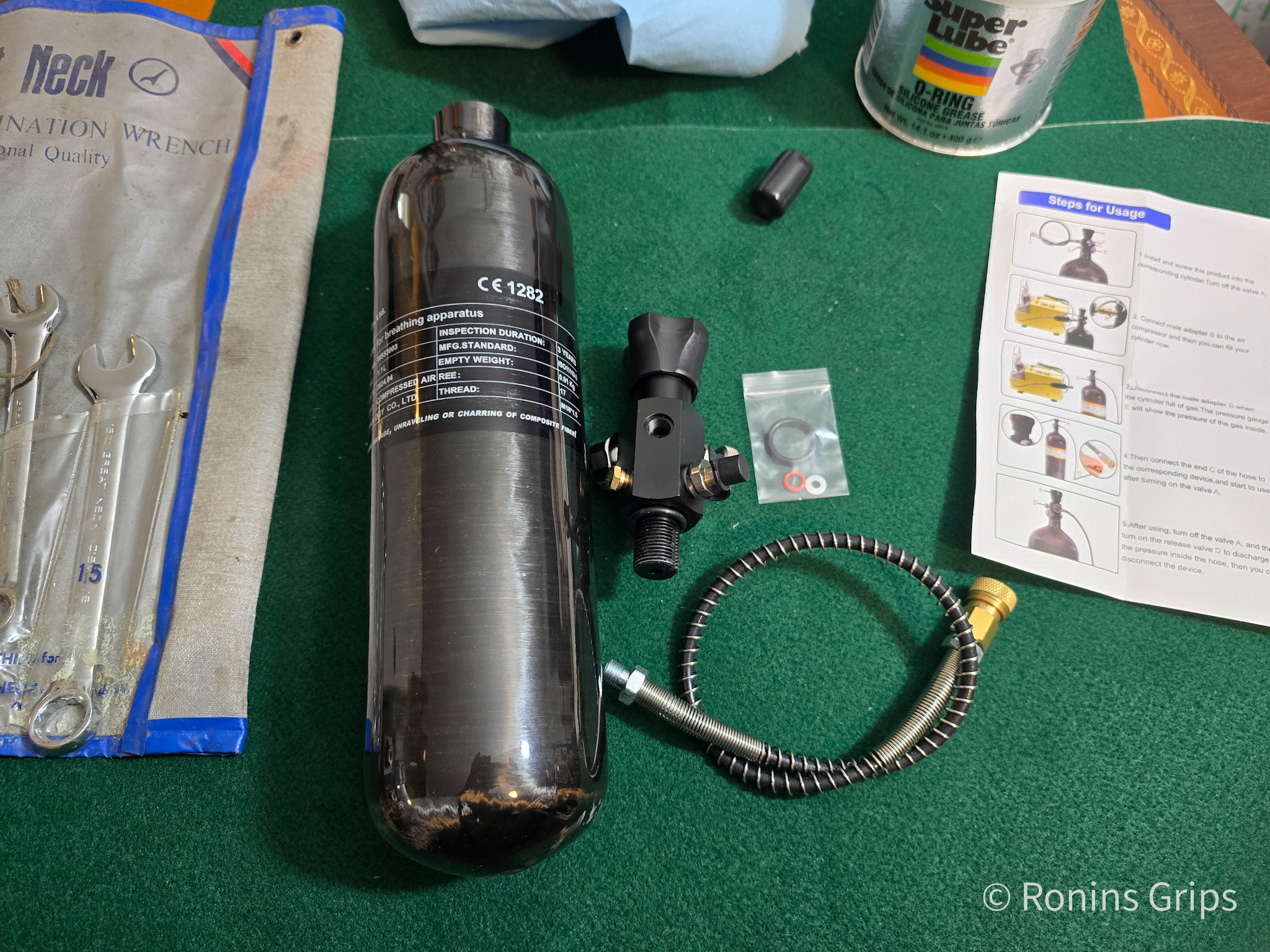
In June 2024, I realized I needed another small tank to top off airguns. I’d sold my Omega to a friend because I had a big bottle and the problem was I had a big bottle (a 6.8L Air Marksman Tank) … It takes a lot more work to whip that out just to top something off. So, I did some digging and decided to buy a small 1.1L/67 Cu In carbon fiber Tuxing air tank off Amazon.
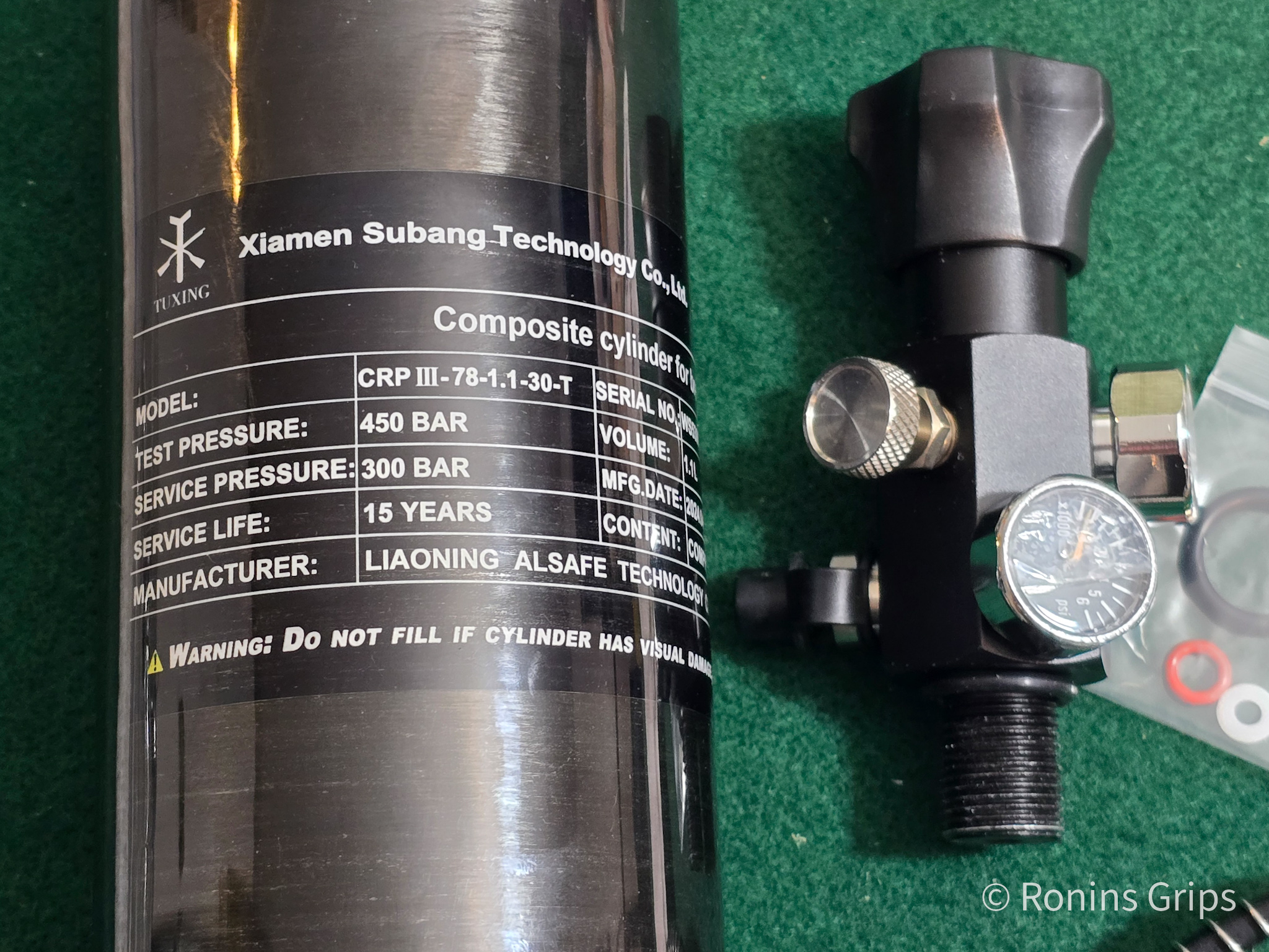
Tuxing is a brand made by the Chinese company Xiamen Subang Technology Co. Ltd., that makes a lot of different products for the High Pressure Air (HPA) and Precharged Pneumatic (PCP) airgun market.
I was a little leery of 4500 PSI in a tank that wasn’t US Department of Transportation (DOT) certified but did some digging and they are “CE” certified for use in the European Union (EU) and also “EN” certified as a storage tank for the EU.
From a safety perspective, the EU certification coupled with good reviews, made me feel safe enough to proceed. Note, since the Tuxing tanks are not DOT certified, I knew I would not be able to get them refilled commercially but since I fill my own tanks I wasn”t worried about it.
I do pay attention to service life though and replace tanks before 10 years pass. Technically, I am supposed to have tanks tested evey 3 years but haven’t been as diligent about that with my PCP tanks as I was with my old SCUBA tanks when I was a diver back in the ancient era of the 1980s and 90s.
Owfeel M18x1.5 DIN Valve
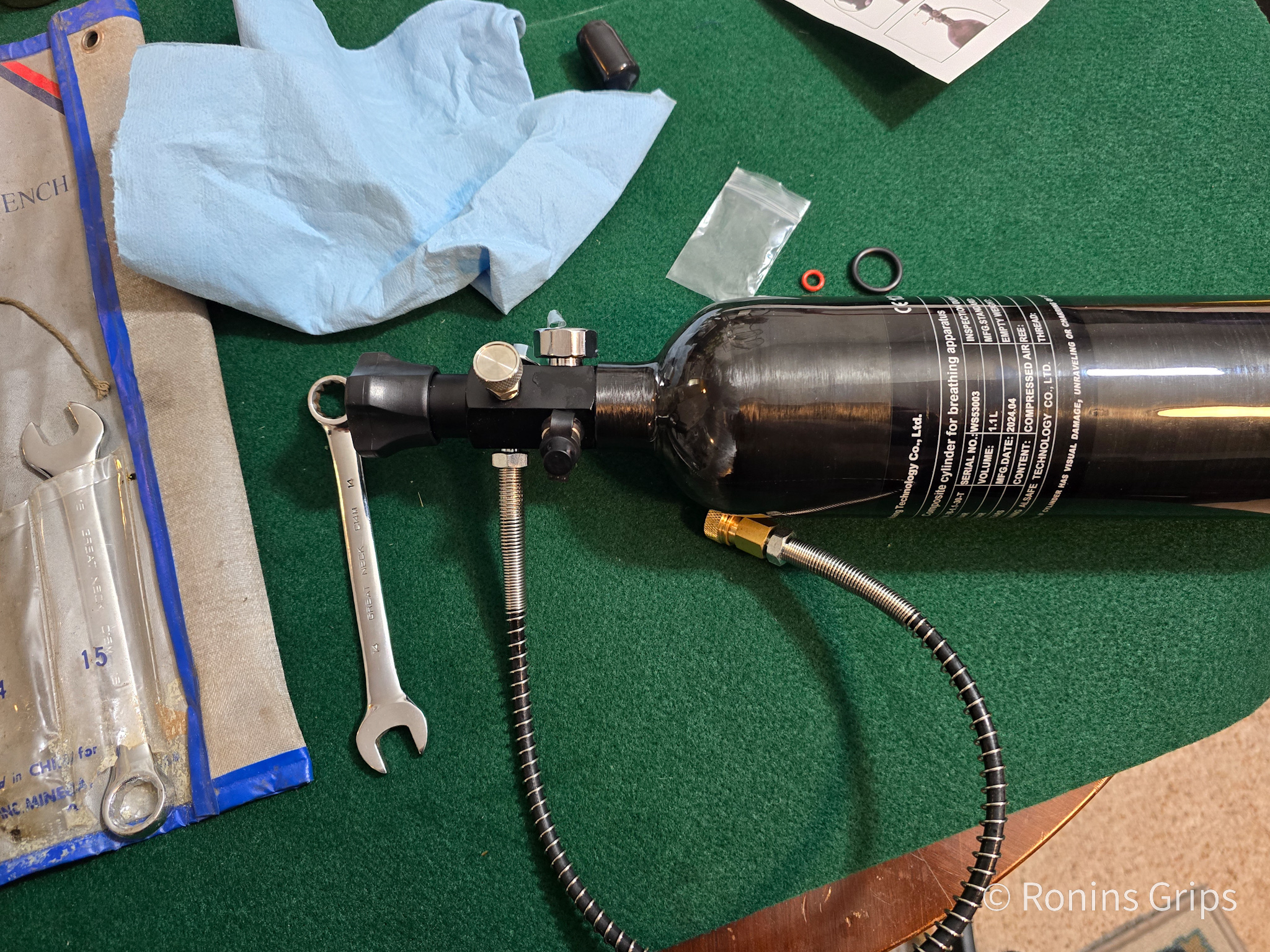
The Tuxing tank is just the bottle and it is threaded for a M18x1.5mm valve. I did some reading and decided to get an Owfeel unit, which is very affordable off Amazon.
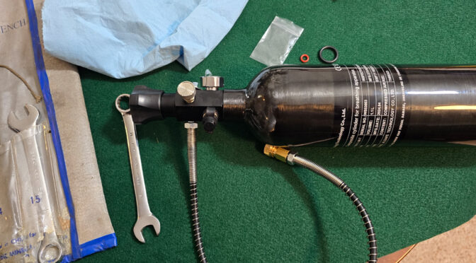
Assembly of the Owfeel Valve and Tuxing Air Tank
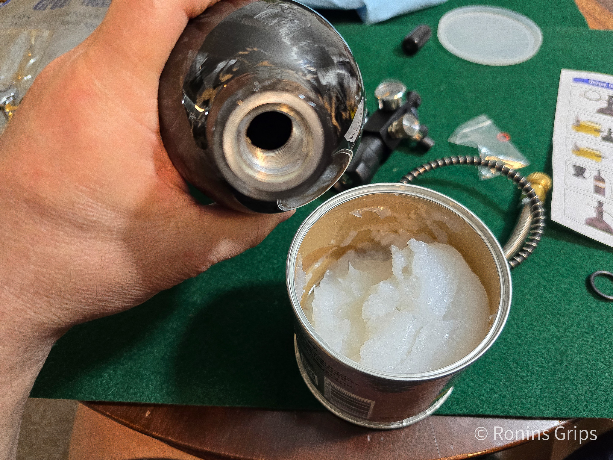
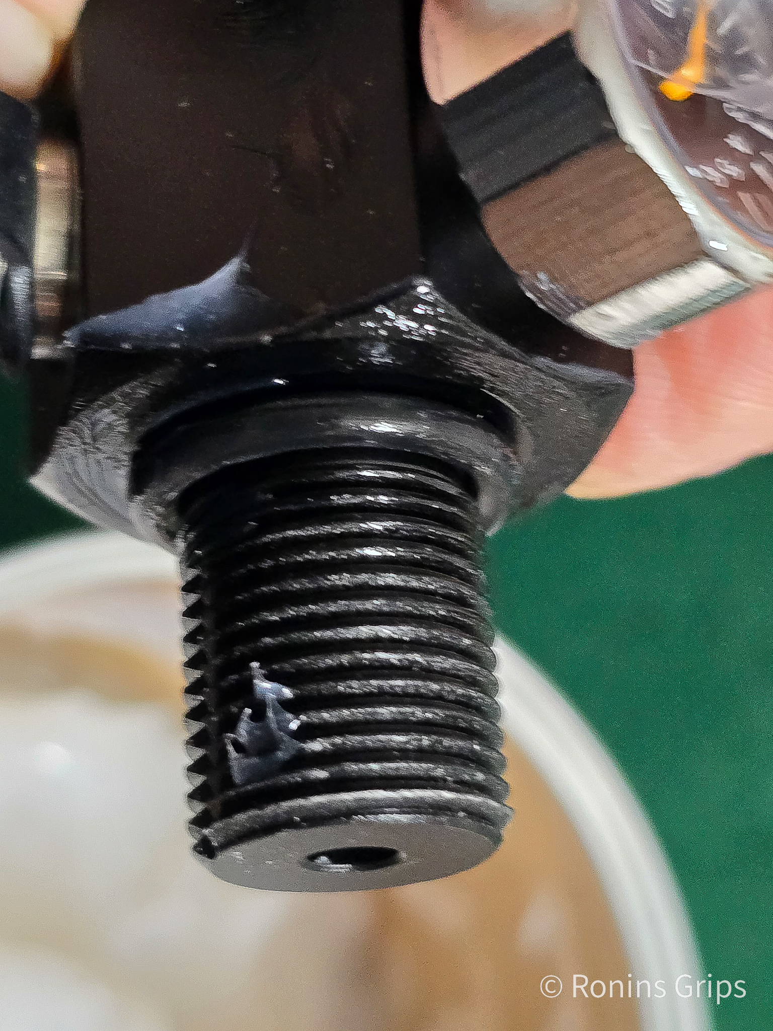
To assembly, lightly coat threads and O-rings with silicone o-ring grease (never use a petroleum product). I use SuperLube’s O-Ring Silicone Grease. The valve is threaded down hand tight onto the tank. The whip for the fill hose can be threaded in and snugged with a wrench.
Testing
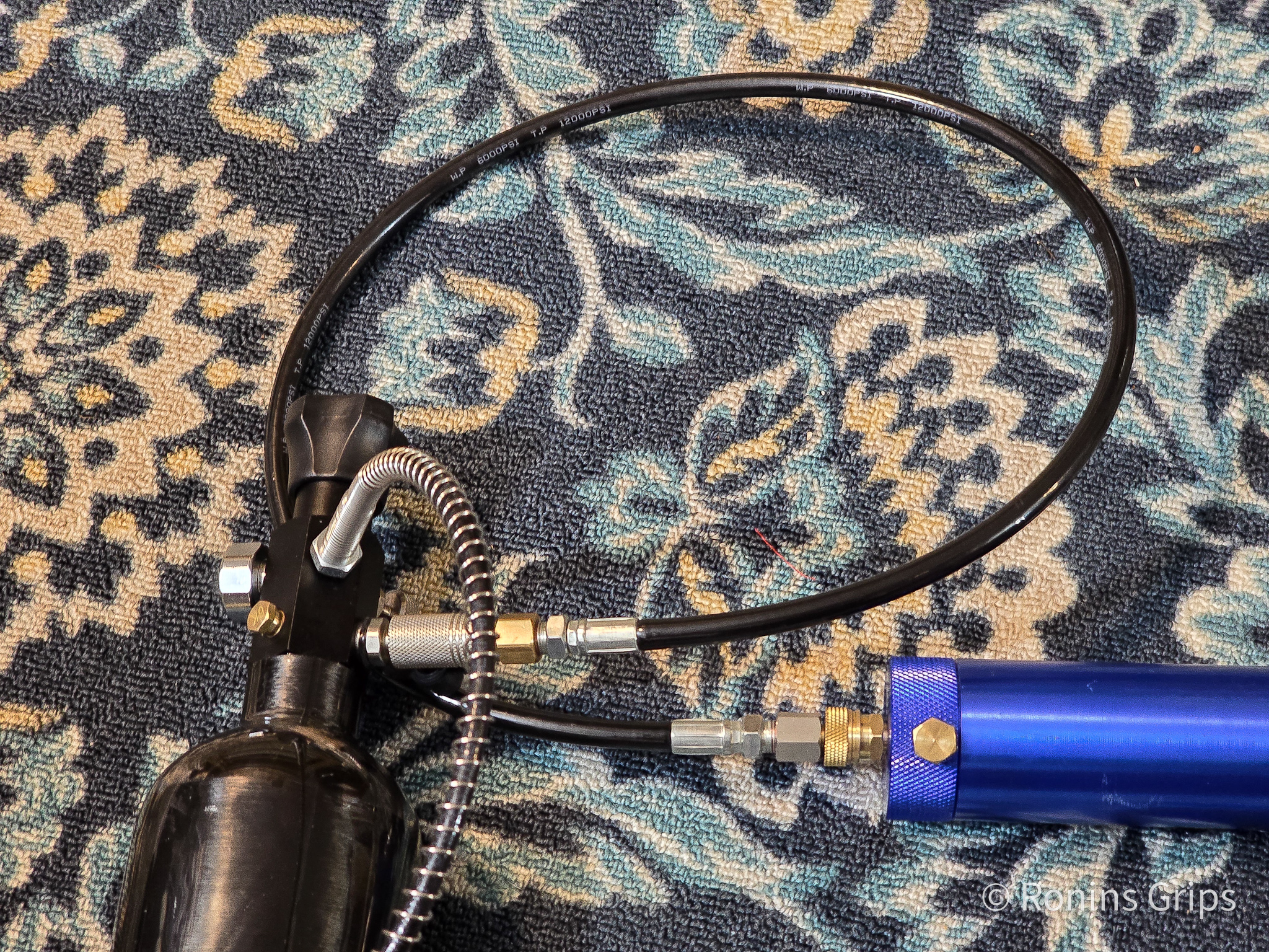
What I do is to put about 100-200 pounds of air in a tank. The exact amount depends on the lines on the pressure valve. I fill to that point and let it sit to see if the pressure holds.
Never run your fingers/hands over high pressure air lines directly touching them feeling for leaks. At high pressures, you risk injecting air into your blood and having an embolism. Instead, use your gauge and watch the pressure. If there is a leak, read more down below about testing. If the leak is in the wall of the tank or the valve body, it is defective and must be replaced.
Start incrementally increasing the air pressure 500 PSI at a time. At each stopping point, make note of where the indicator is on the gauge, wait 10-15 minutes and see if the pressure leaks down. Fill, wait and watch. Over and over until you reach the maximum pressure.
When you hit the maximum pressure, let it sit and check it at 30 minutes, 60 minutes and then at two hours. It should be holding pressure.
If you have a leak
If you detect a leak, spritz soapy water at the quick connects first – they are the most common leak. If leaking, try repositioning. If it is still leaking, drain the air and replace the fitting.
If still leaking, next check the o-rings where the hose goes into the valve and where the valve goes into the tank. If either leaks, let out the air, is one loose? Do you just need to snug it up? If the connections are solid, then the o-ring may be bad and need to be replaced, try that.
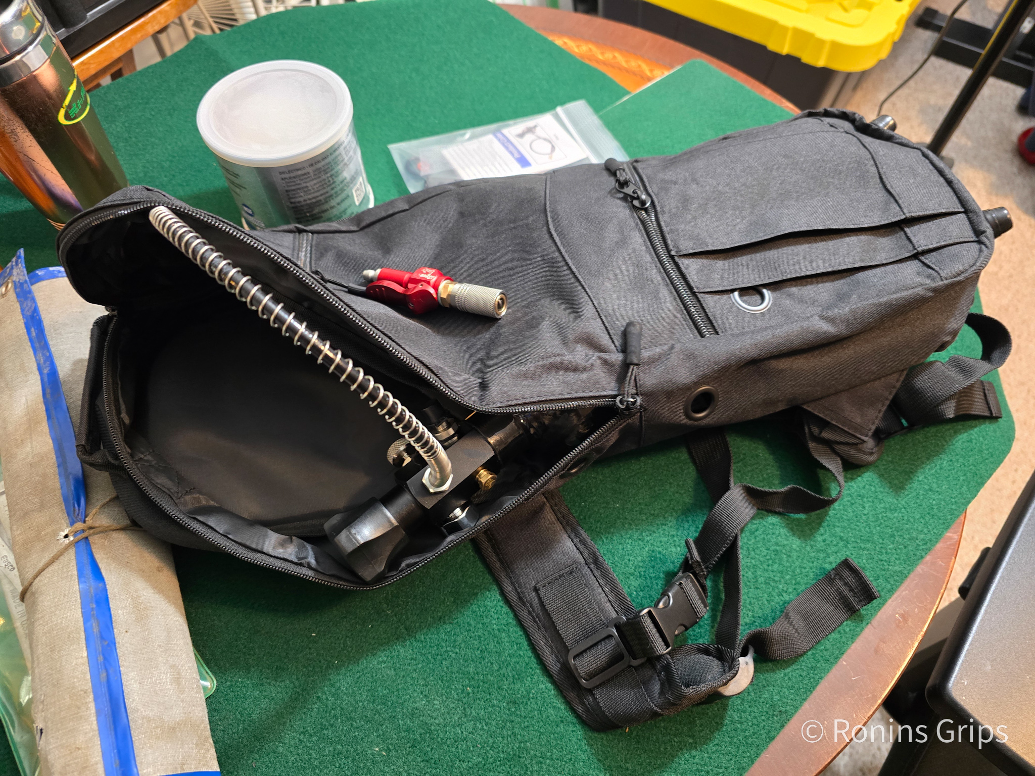
Storage Bag
I wanted a case to put the unit in a case and realized an oxygen bottle bag would work great. The one I bought is an iGuerburn size D oxygen tank backpack from Amazon.
Summary
The Tuxing air tank and Owfeel valve make a good affordable compact combination. The unit is small, light and easily fit in the iGuerburn Size D oxygen tank bag I use to both store and move it around in.
I hope this helps you out.
Click here if you would like to visit the Tuxing store on Amazon.
Click here for their air tanks.
Note, I have to buy all of my parts – nothing here was paid for by sponsors, etc. I do make a small amount if you click on an ad and buy something but that is it. You’re getting my real opinion on stuff.
If you find this post useful, please share the link on Facebook, with your friends, etc. Your support is much appreciated and if you have any feedback, please email me at in**@*********ps.com. Please note that for links to other websites, I may be paid via an affiliate program such as Avantlink, Impact, Amazon and eBay.