I have wanted to build an IMI Galil from a kit for years and just never got around to it. One thing that kept me from jumping in was that I had never really dug into the design deeply by taking one apart and looking at everything.
In 2006, like a lot of guys, I read the late Steve Matthews great article in Firearm News about building your own AK rifle or pistol. For whatever reason, the AK building bug bit me hard and I wound up with a number of barreled Romy-G kits along with flats, rivets and tools from AK-Builder.
I read everything I could and guys kept telling me you “just gotta dig in, do it and learn”. Well sir, I did. I trashed my first flat or two – I think I messed up the bend on one and the other I ruined the top rails as I didn’t cut them right. Yes, back in those days we had to put Dykem Blue on the top rails and scribe a line to cut to using a layout jig AK-Builder eventually came out with. I messed up a lot and I learned a lot.
A fair amount of the mistakes were caused because I had never really studied AKs prior to trying to build my first one. Over the years I have learned a ton more but one lesson sure has stuck with me – it’s way easier to build something if you have first had experience with the design including disassembly.
Fast Forward To December 2020
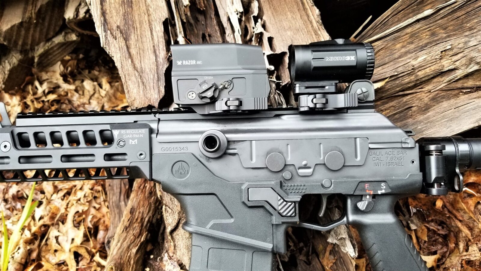
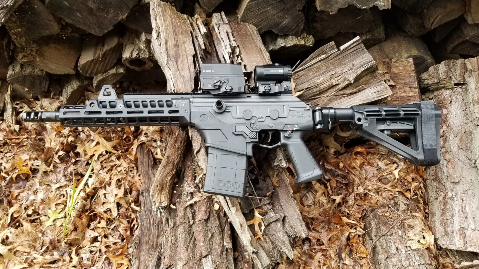
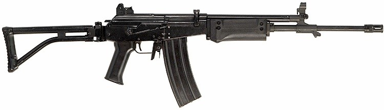
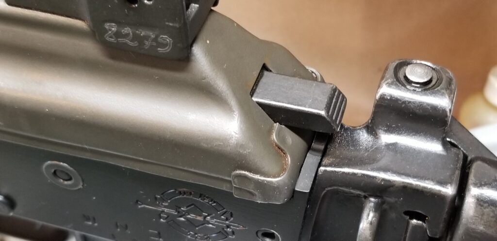
Everyone was in a panic buying everything firearm oriented in sight and I was trying to figure out whether to make the slightly sideways leap from AK designs that I knew to a Galil that was based on the Finnish RK.62 and had a screw in barrel (not pressed and had to be headspaced, the extractor cut and barrel populated later), some wierd looking thumb selector (no idea what that linkage was going to look like) plus I was sure I would run into other little unque surprises.
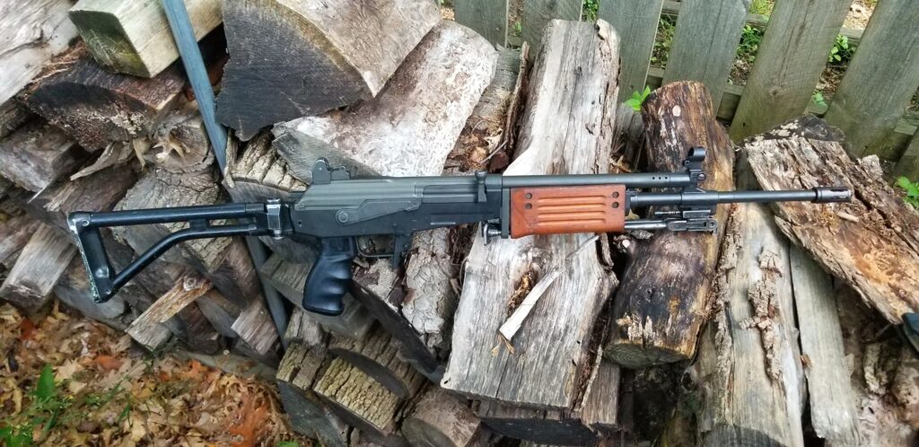
So I took a rather odd gamble. Other than custom shops, like the amazing Jeff Miller at Hillbilly Arms, there are two shops cranking out IMI Galil clones using original Galil ARM and AR kits married to new US barrels and receivers. ATI and their Galeio and James River Armory (JRA) and their Gallant, which uses Galil ARM kits. Note, they are using new receivers and appear to have corrected issues they had with their earlier 2019-ish models.
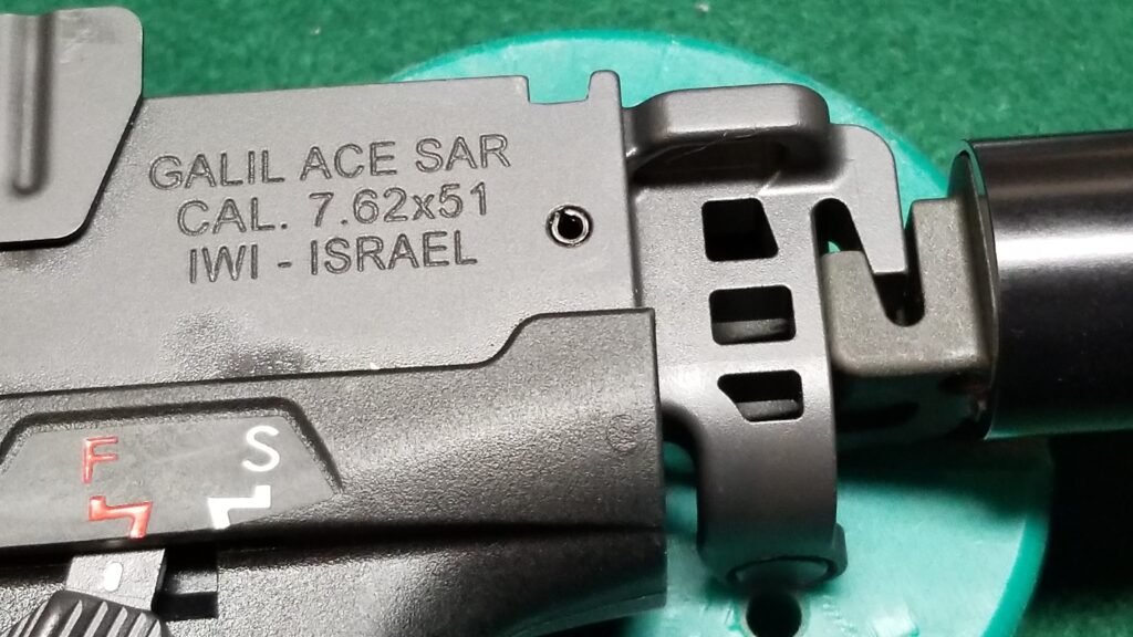
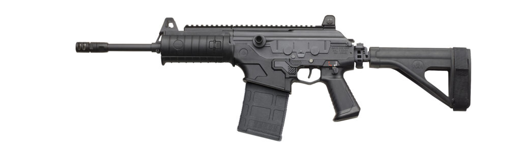
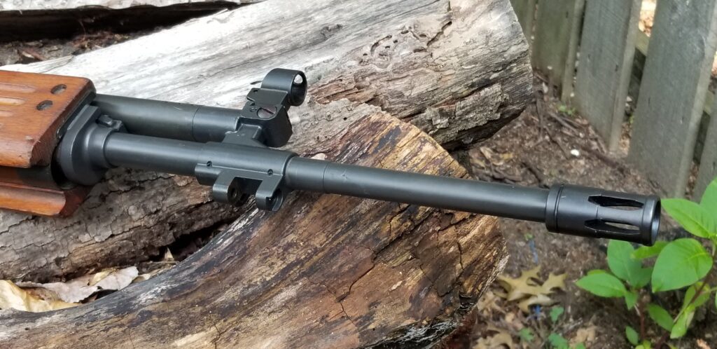
The JRA seemed to get good reviews and was affordable around $1,000. Now, a receiver will run you $400-500 once you include S&H plus your FFL’s transfer fee. A barrel will run you $99-199 depending on what you get and then you will spend another $300-400 for a kit. All of a sudden, looking at that JRA rifle as a parts kit became really attractive plus they use an 18″ 1:9 twist that can stabilize up to 62 grain M855 “green tip” bullets – actually it can go up to 72 in theory but I wanted to be able to shoot M855. The original Galil’s had 1:12 twists that could stabilize the older M193 55 grain rounds but not M855 – when you see targets where guys fired M855 rounds through a 1:12 Galil barrel, the bullets often “keyhole” or hit sideways. So, the 1:9 twist rate really appealed to me.
Apparently JRA has an exclusive distribution agreement with Classic Firearms. It’s interesting really – Classic has a number of Gallant models and their description is actually quite thorough in hindsight – Classic was sold out but I turned on notify for the Gallant models I was interested in and maybe 2-3 weeks later I got a notice that one was back in stock so I jumped and ordered one – this is the link for the one I bought.
I wish I could say it went smooth but FedEx’s Ground Service (the old RPS group they bought years ago) threw a big monkey wrench in things. Classic shipped promptly but FedEx Ground’s South Bend office has been having huge problems due to lack of staff. It took maybe 2-3 weeks from when they got it until they actually delivered it to my FFL.
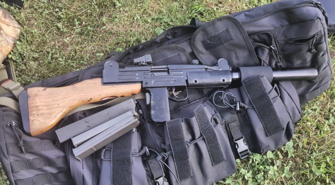
Scott Igert, the owner of Michigan Gun Exchange is a good friend of mine and I use him for all of my FFL needs plus he has the best gun store in Southwest Michigan in my honest opinion. At any rate, Scott sent me a photo of an AK and told me my Galil was in. Leave it to Scott to pull a prank and I knew full well he knew what a Galil looked like so he didn’t get me as good this time … unlike other times 🙂 That’s what friends are for.
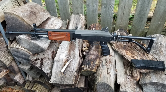
At any rate, I went and snagged the Gallant, took it home and promptly took it apart. I didn’t really care about the warranty because short of some huge problem with the receiver or a bent barrel, it wasn’t going back.
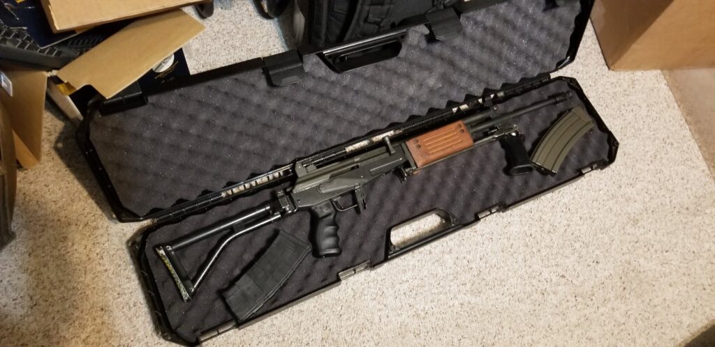
So let me itemize my observations
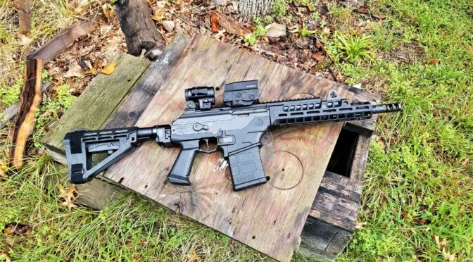
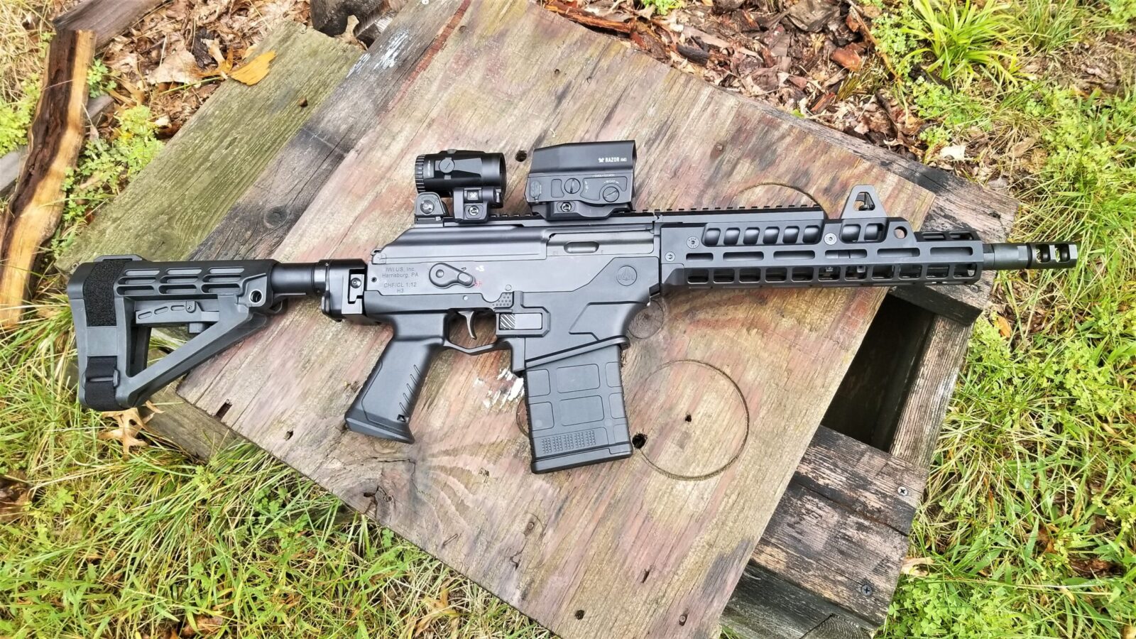
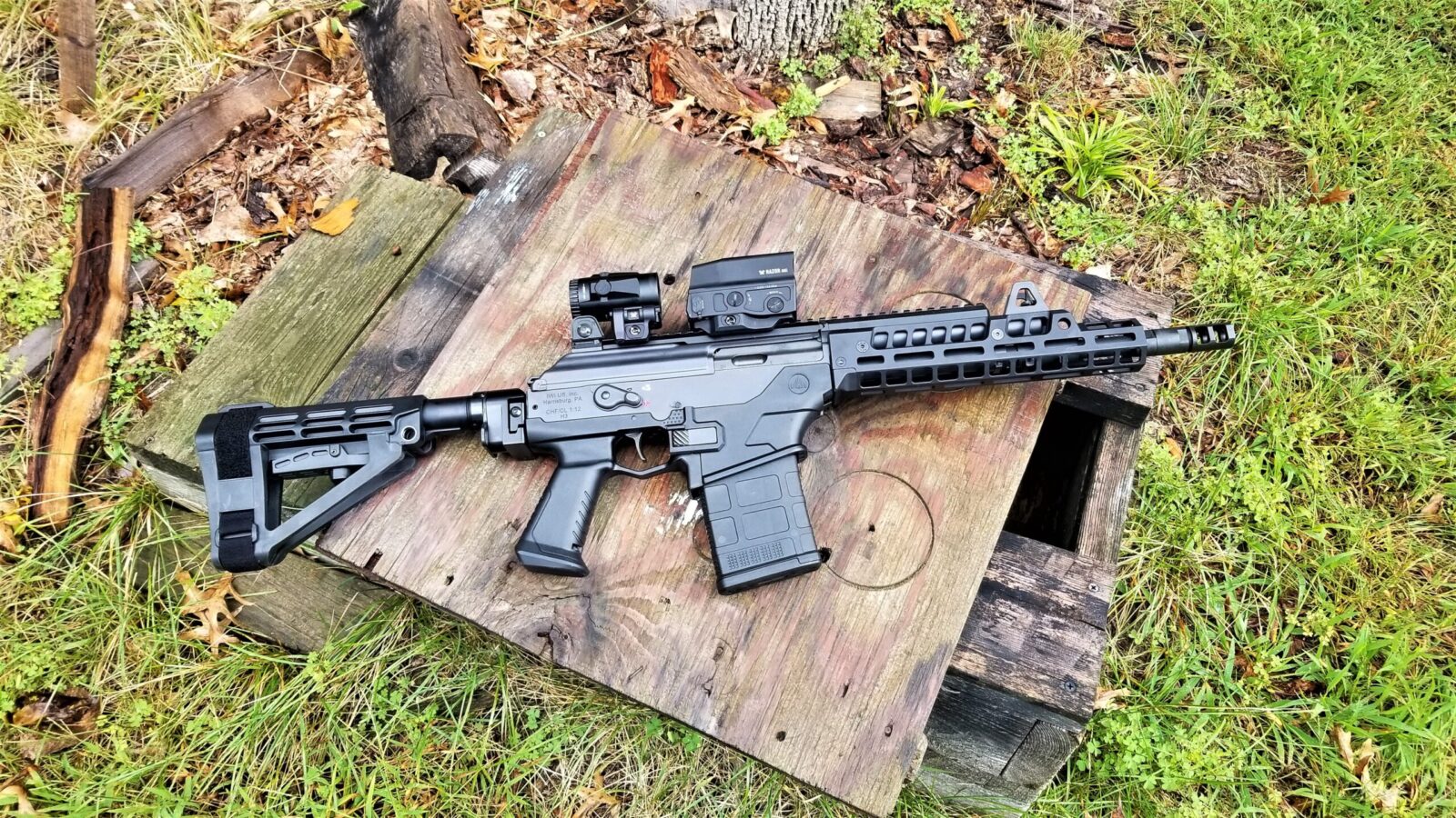
They tell you right up front it is supposed to look battle worn. The skeptic in me thinks it was a way to cut costs but another side of me likes the look – the receiver and barrel are black, parts with the original finish have the grey/green parkerized finish on them and the wood has a look that only a ton of grease oil and God knows what can achieve. I actually found myself liking it.
For 922r compliance, they have a US 1:9 barrel, a US receiver, a US Galil-Ultra looking grip made my Phoenix Technologies here in the US and a US Tapco magazine. Now that last one gets a bit of a groan – the Tapco magazines are plastic, they work, but there are a ton of nice steel surplus 35 round mags out there that would make the rifle no longer 922r compliant if inserted. As best as I can tell, they used an original Galil fire control group with it’s forged trigger hooks and two part spring setup – one spring for the trigger and one for the hammer – if it is aftermarket, it is not marked.
Note, I emailed JRA and asked them about the compliance parts. So far, they have not responded. Classic says on their web page that surplus mags fit (and they do by the way) but there is no mention of compliance.
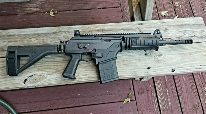
Now, there are a two primary mindsets out there when it comes to 922r compliance: Some worry about it because they want to be legal. Some don’t care for whatever reason and that is their decsion. As for myself, I ensure that anything I build or modify is 922r compliant. So, I wanted to use steel surplus Israeli mags so I decided to swap out the original IMI hammer, trigger and disconnect with a new ALG enhanced fire control group (FCG). Yes, an AK FCG will work in an IMI Galil. If Classic tells me they actually sourced a US made IMI-style FCG, I will update this. I’m writing this post after already making the change to the ALG.
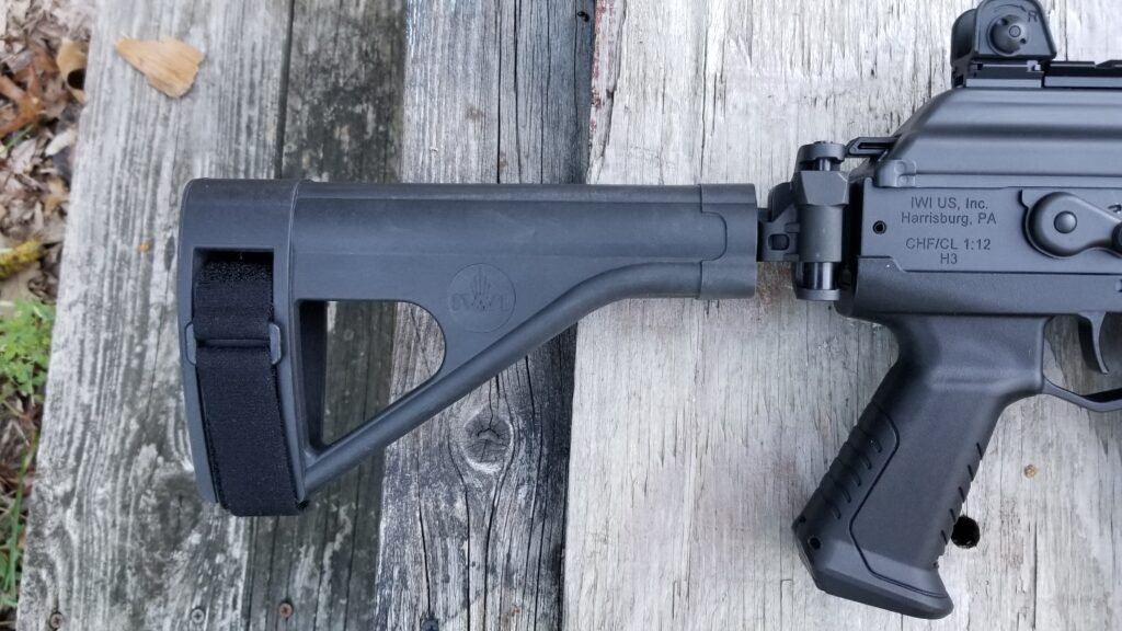
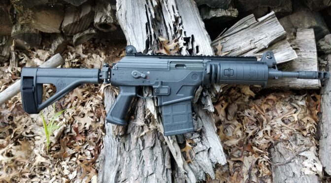
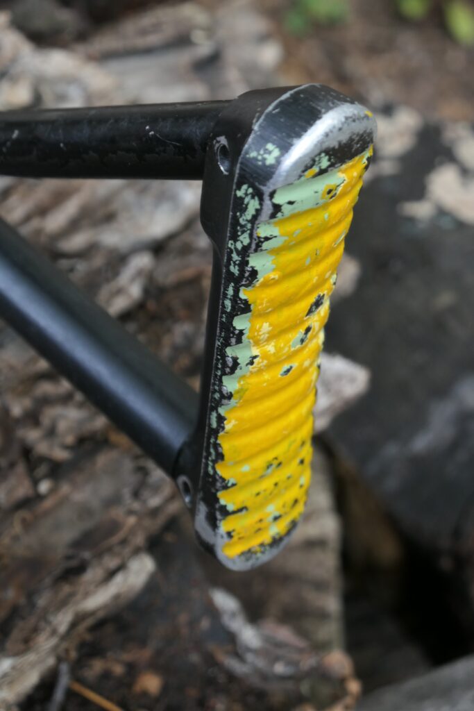
The buttstock made me groan. It had a giant splash of yellow paint on the very butt of the stock for some reason. The color was hideous, the horizontal tube had a few small nicks, and the finish was a bit more beat up than I preferred so decided I would swap it out for one in better shape from a SAR kit I had.
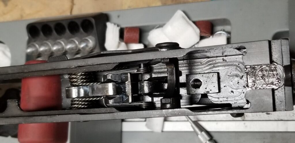
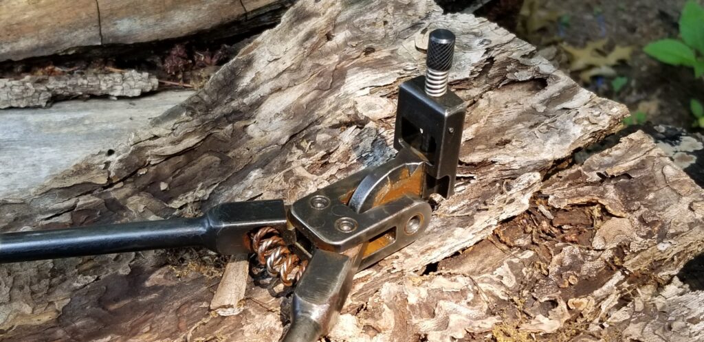
The rifle did come with an ARM bipod but it had a bunch of rust in the mechanism. It worked but definitely need cleaning and refinishing.
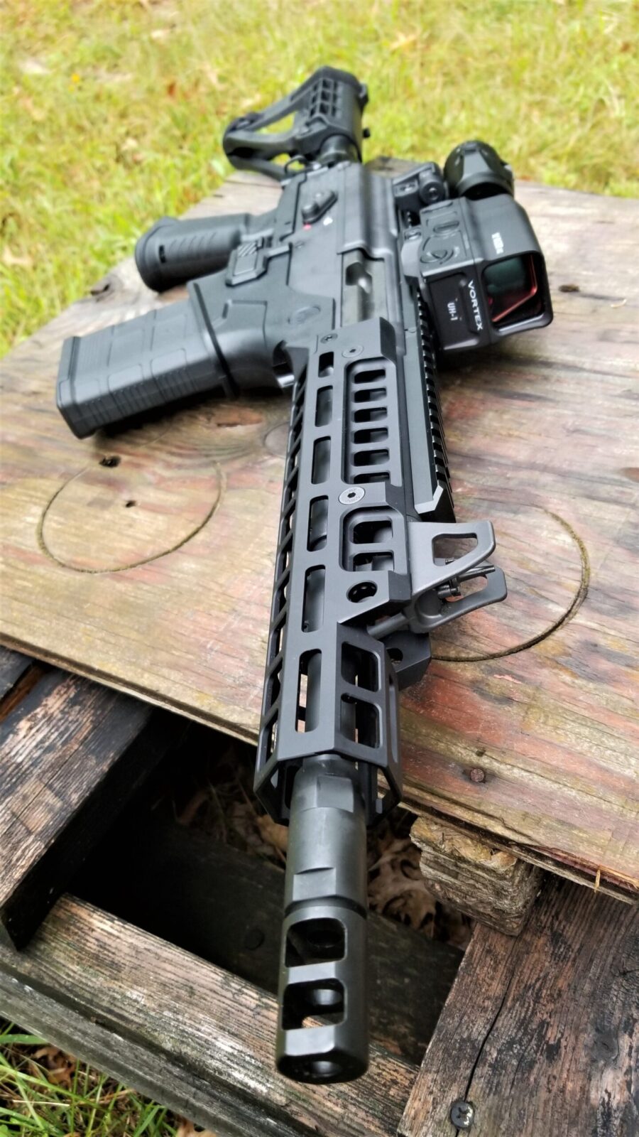
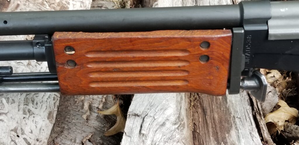
The handguard was way, way to loose. This was pointed out in the ad so I expected some – but not what I felt. I don’t like it when they shake and rattle so that needed to be tightened up. The wood was in good shape though and I really liked the coloring.
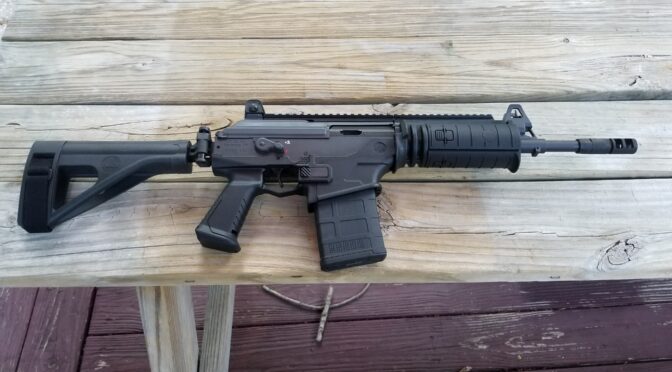
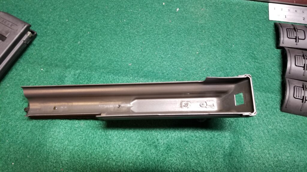
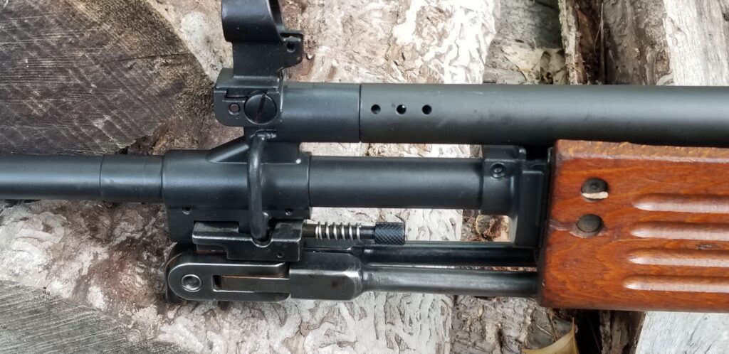
The barrel looked good – it was not bent and the components were installed right — other than the notch for the handguard not being close enough as mentioned previously. The bore was also nice and shiney with nice sharp rifling.
The top cover is still driving me nuts when it comes to installation. It is a delicate balancing act to get the recoil spring assembly to stay in the receiver groove and go into the dust cover vs. going out of the groove and falling into the receiver. I have some Galil receiver stubs and I want to see if the receiver that JRA used is too short or if the IMI suffered from the same headache. I haven’t decided yet if I just want to live with it or cut the tab down about 1/8th-3/16th of an inch shorter, cut new grooves in it and the refinish the whole rod assembly.
Happily the rifle was properly headspaced and it fed rounds nicely. For a kit built rifle, it cycled and the FCG operated smoothly – surprisingly smoothly. Okay, it looked like I had a solid foundation to build on. So far, so good.
At this point, I knew I was going to keep it so it was time to start making changes. I put the rifle back together and started thinking about what I was going to do. I’ll detail what I did in subsequent posts.
Note, I have to buy all of my parts – nothing here was paid for by sponsors, etc. I do make a small amount if you click on an ad and buy something but that is it. You’re getting my real opinion on stuff.
Please share the link on Facebook, Forums, with colleagues, etc. Your support is much appreciated and if you have any feedback, please email us in**@*********ps.com. If you’d like to request a report or order a reprint, please click here for the corresponding page to open in new tab.