The Hatsan Gladius is a pretty cool precharged pneumatic (PCP) air rifle. You get a long of bang for your buck but it does lack an important feature needed to get more consistent accuracy from the rifle – regulated air pressure.
The stock Gladius has a power setting but it does not have a consistent air pressure supply. What a regulator does is allow you to have the reservoir set at one pressure and then the air fed to the rifle is set at another. For example, the Gladius’ cylinder is rated for 200 bar (3,000 PSI). You can set the regulator for 130 bar, which is a popular setting, and you always get 130 bar until the pressure of the cylinder dips below 130 bar. This not only helps you have a far more consistent pressure but also the number of shots increases because a lesser volume of air is used with each shot due to the regulator.
In talking with folks, the most recommended regulator I could find for the Gladius is made by Huma in the Netherlands. You can order direct from them, which I did and my two regulators arrived in less than a week. I should also point out that they were very prompt in replying to my questions, which I really appreciated.
In this blog post I will cover how to install the Huma based on what I learned while trying to install the regular. I would also recommend that you read the instructions from Huma to make sure you get a better understanding of what is needed. With the Gladius, installing the regulator is relatively easy because it goes into the removable air cylinder.
Step 1: Mark the bottom of the cylinder. I put a piece of tape and marked the bottom of the cylinder while it is screwed all the way into the rifle. You must do this because the regulator has a top position that must be oriented properly when the cylinder is screwed back in.
Step 2: Remove the cylinder from the rifle. It simply unscrews counter-clockwise and you may need to pull the cylinder to overcome resistance caused by the O-Rings.
Here are the instructions but before you do anything – MAKE SURE YOUR CYLINDER IS EMPTY [Click Here For Instructions to “degas” the cylinder]. There is a pressure gauge at the end of the cylinder and it should read zero.

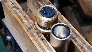
Step 3: Remove the brass valve assembly end of the cylinder. Use a 13mm wrench to turn the brass fitting counter-clockwise and unscrew it from the black aluminum tube. This should turn easily. If it does not, install the degas tool, turn the set screw and ensure all air is out. This brass valve assembly should unscrew fairly easily. If it is taking a lot of torque to turn then this may indicate that the cylinder is still under pressure. If it is empty and still does not want to turn then there may be a threading issue and you need to decide if you want to apply more force or contact Hatsan. Again, on my cylinder this came off very easily with me holding the aluminum tube with one hand while turning the 13mm wrench with the other. The 13mm wrench sits on a flat spot on the valve body made just for this purpose.


Step 4: Watch out for burs. The machining inside the cylinder and the valve body are all quite sharp. Be careful when you are turning things by hand. If you see any visible burs remove them or you may slit the O-Rings of the regulator by accident.
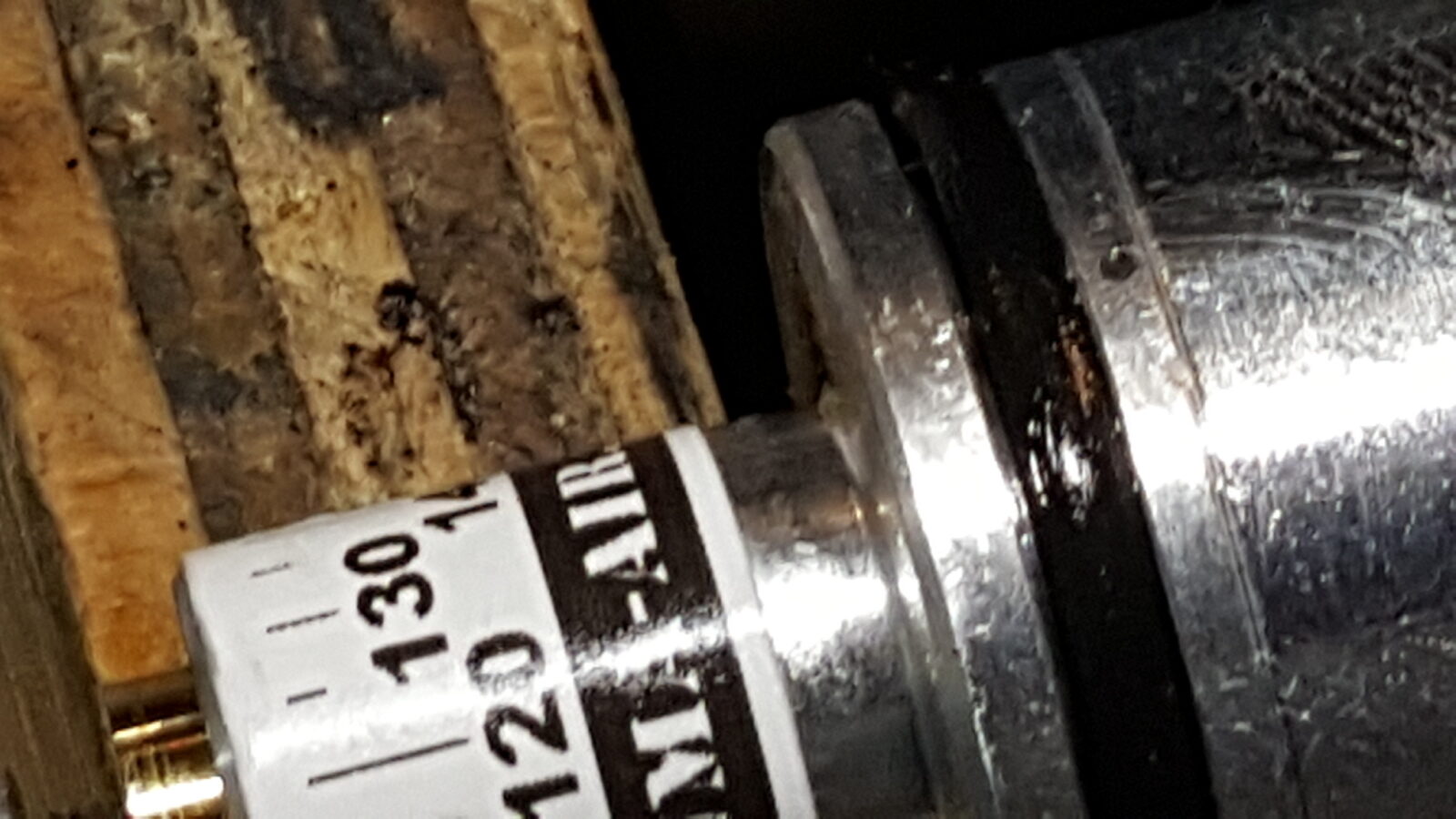
Step 5. Prepare the Regulator. The regulator is one piece. The online instructions mention and show a separate spacer that is no longer there. Set the pressure by aligning the brass dial with the pressure markings on the tape. You would do this by removing the small 3mm screw and using a blade screwdriver to make the adjustment. I ordered mine set for 130 bar so I didn’t need to do anything but the screw did confuse me as I couldn’t figure out what it was for – it was loose and just sitting there. I contacted Huma and they told me that this screw is meant to be loose and serves as an air flow restrictor. To set it, screw it down until it stops and then back it off two full turns. I had to do this because I removed the screw trying to figure out what it was before I asked Huma. What I did was hold the screw and rotate the body because that was very easy for me to count two full turns given all the markings. Huma told me to leave the screw loose so that is what I did.

Step 6. Grease and seat the bottom O-ring. Grease everything lightly with silicone grease. DO NOT USE A PETROLEUM GREASE. It must be silicone grease to be safe. Make sure the bottom O-Ring is in place. This must be done outside of the air cylinder and greased there as well. This is critical – if you do not grease this O-Ring and the bottom of the valve then it may well twist out of position as you tighten things together.


Step 7: Option – notch a small V in the front of the top of the tube to better enable venting. Huma reports there are two ways to make sure the regulator can vent properly. One is to simply not screw the brass valve back in all the way or take a file and make a tiny notch on the top inside edge of the cylinder before the threads. I opted to do this as I don’t like the idea of having a loose valve body moving around unpredictably when installing or removing cylinders so I just took a small file and made a tiny notch at the top of the cylinder (opposite from the bottom mark you should have made with the piece of tape). I did this with the valve sitting horizontally and then wiped out the tiny aluminum shavings and then blew it out too. I applied the silicone grease after I filed the small notch but took the photo after I greased it so that’s why you see the grease.

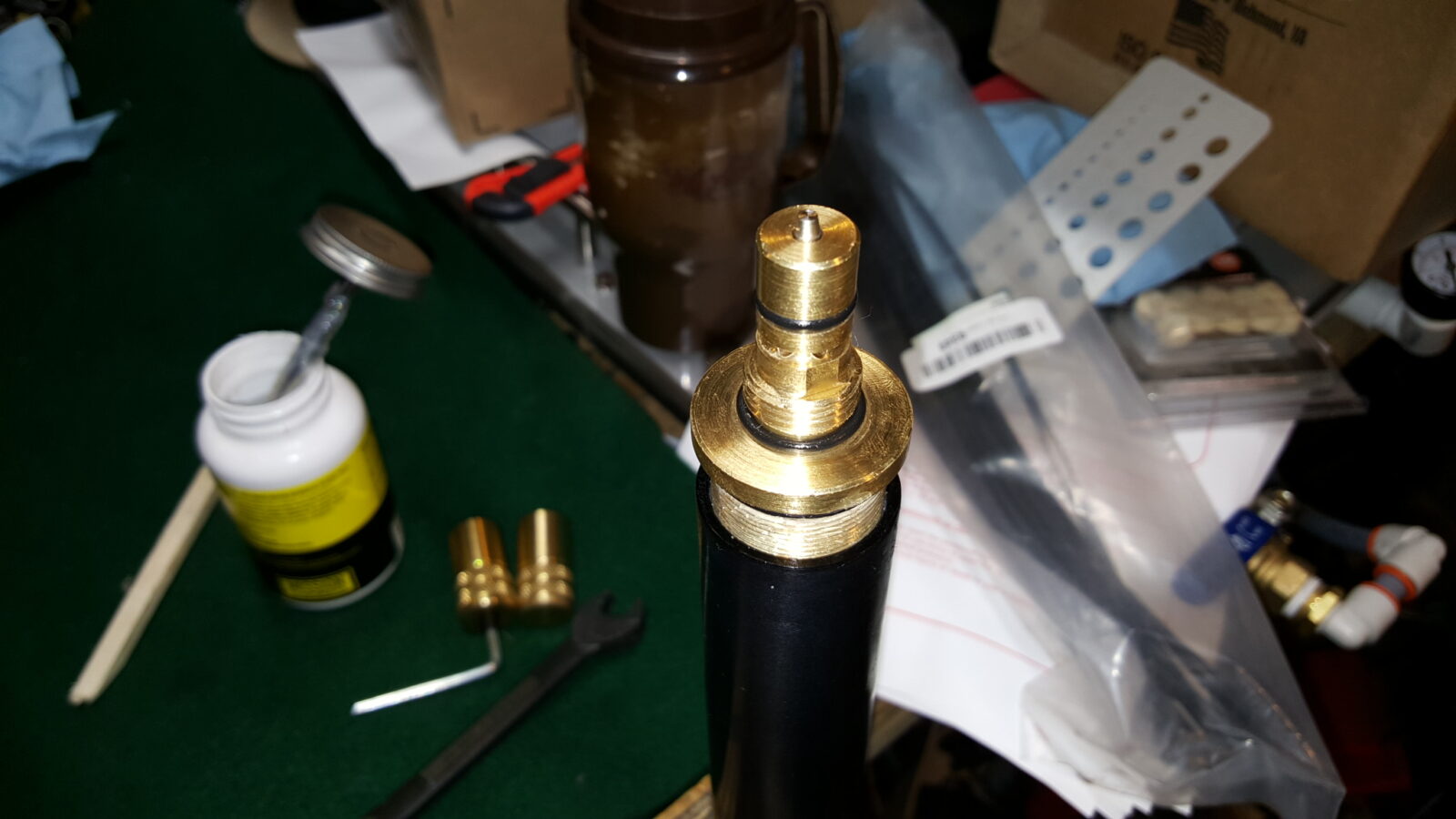
Step 8: Grease everything and insert the regulator. Ensure the regulator, threads and the first 7mm(ish) of the cylinder after the threads have the silicone grease. To install the regulator, you must orient it properly. There is a tiny vent hole in the body of the regulator just below the O-ring that must be at the top of the cylinder where you also made the small notch. Now the screw end of the regulator goes in first. So hole up and screw first. Gently insert the regulator and use a dowel to push the unit into the cylinder. There will be resistance as the O-Ring pushes past the threads in the cylinder walls. You really do need a dowel or something to help you push it in while avoiding that bottom O-ring. If you push on the O-ring with your fingers, it will probably come out — I know this because I did that and it came out and I had to tap the cylinder on my wood work table to get the regulator to come back down so I could fish it out. What you want to do is slide it down just past the threads. The air pressure will push it back against the valve body when you fill the cylinder.

Step 9: Reinstall the brass valve body. As mentioned previously, you have two options – either make the notch and screw the body back on all the way or do not thread it back on all the way so the air can vent from the regulator more readily.
Just for reference, if you don’t want to notch the inside edge of your tube, they say to tighten down the brass valve assembly and keep about a business card thickness gap in it. Again, I made the notch in the top and tightened mine down.
Step 10. Pressurize and check for leaks. So, I used my Hill hand pump and gave myself three targets taking breaks at 50, 100 and 150 bar until finally I reach 200 bar. It is a fair amount of work so take your time, take breaks and let your body weight work for you if you go that route. At any rate, I checked for leaks at each stop with soap water. So far, so good.
Now I just need some time so I can do some shooting and compare my unregulated cylinder to my 130 bar regulated cylinder and report the speed, accuracy and air consumption. That will be for another day.
Please share the link on Facebook, Forums, with colleagues, etc. Your support is much appreciated and if you have any feedback, please email us in**@*********ps.com. If you’d like to request a report or order a reprint, please click here for the corresponding page to open in new tab.