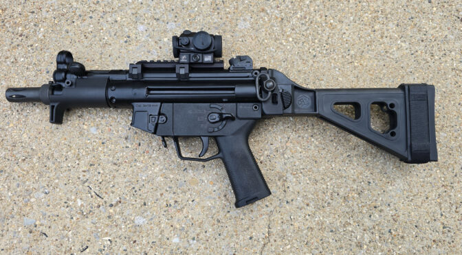
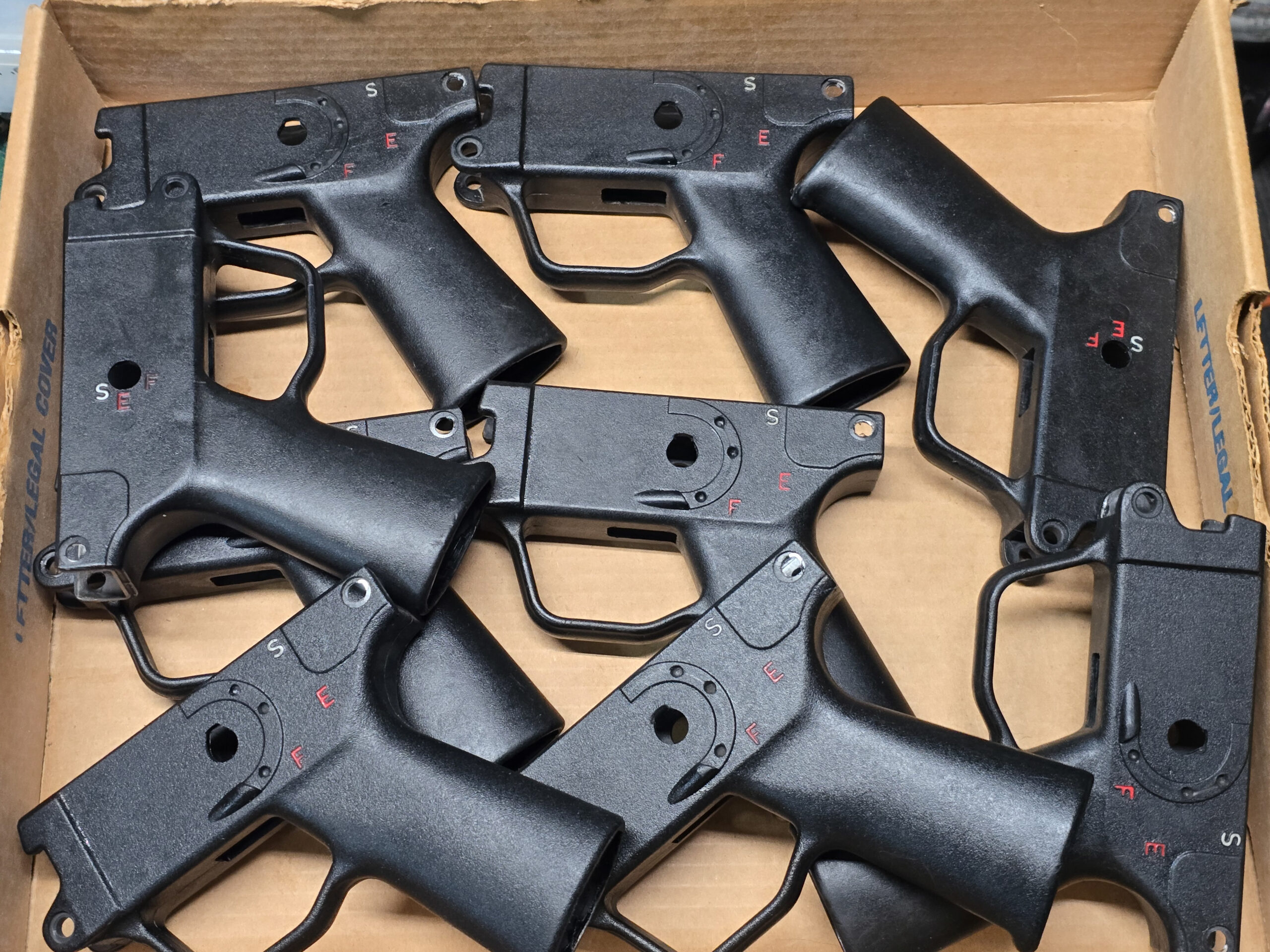
It’s taken a while to work out the processes and tooling but now we have a variety of grips converted for HK MP5K weapons and their clones including:
- Century / MKE AP5-P and AP5-M pistols
- HK MP5K, SP5K – for the SP5K, slight trimming of the front locking plate on the grip will be required
- POF 5PK
- PTR 9KT
- Zenith ZF5-P, ZF5-T, and ZF5-K
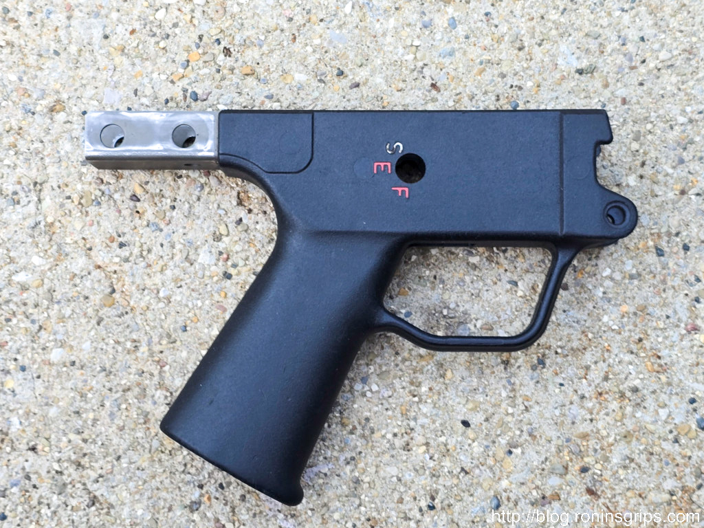
There are three required features for these to fit:
- It must be an MP5K pattern weapon and not an MP5 or other variety of roller lock.
- It must have an HK MP5K patterned top rear hole.
- It must have a front shelf that the grip’s front locking plate rests on.
Technically, our Contract Contour and Navy SEF grips do support the front lower pin that some MP5Ks use. However, our converted Magpul SL grip does not have a front lower pin and does not need it because it is pushed forward against the weapon’s shelf and can’t slide out of position.
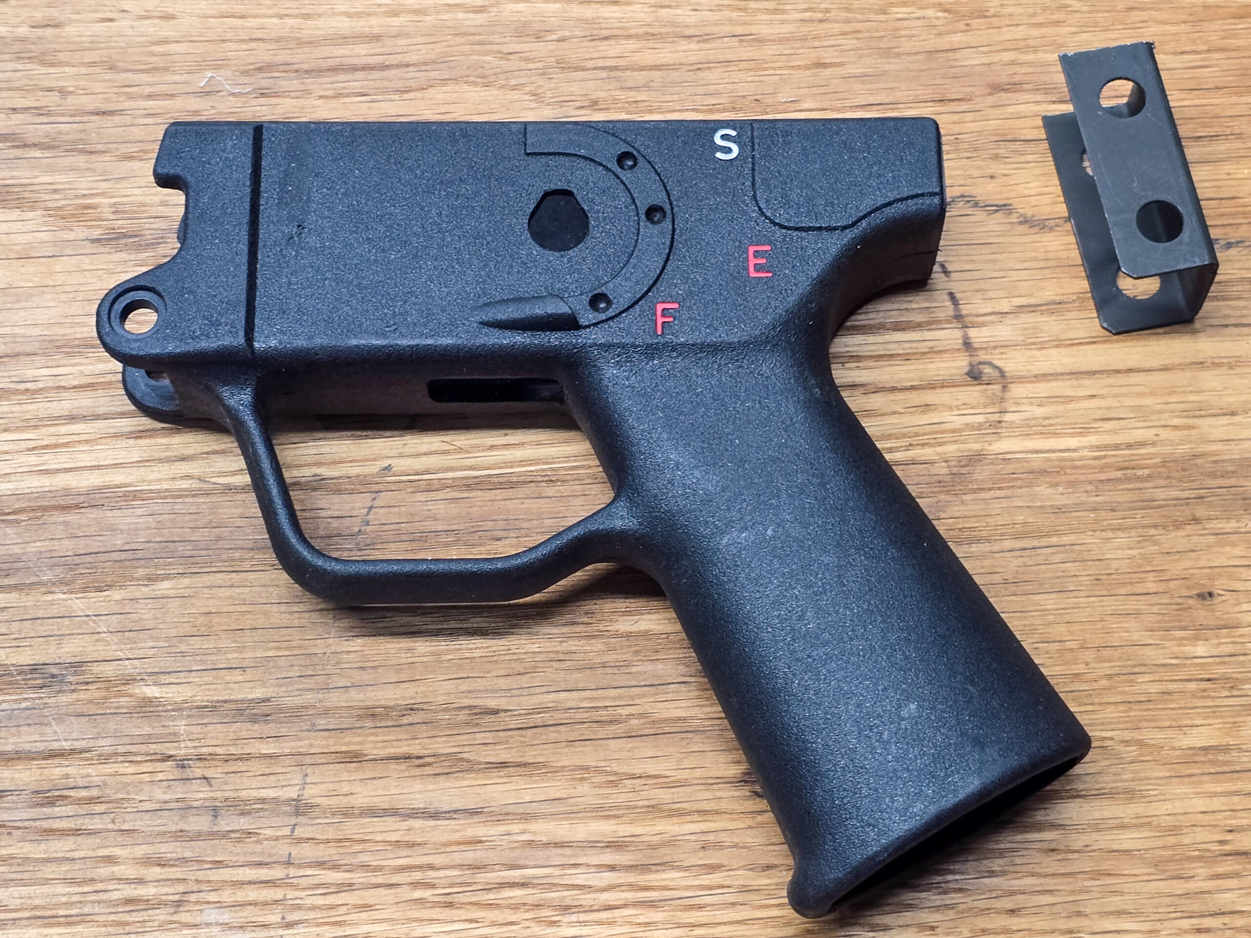
How They Are Made
Interestingly enough HK33, HK91/G3, HK93, HK94, MP5, and MP5K grips all have the same size polymer core grip albeit with different metal “tails” sticking out of the rear to accomodate whatever weapon they are meant for. Now there may be other models out there as well – but those are the ones that I know of so far.
The first step if you have one of these model grips is to removed the “tail” so the length will be correct for a MP5K, I would recommend cutting off the tail and then deburring it. Do not remove any polymer so you can get a firm fit when you install whatever stock, brace or end cap you plan to use.
Measure the Existing Rear Hole Centers and Countersink Depths
To cut the rear holes is a bit more involved. First, you need to locate the centers of your existing MP5K grip’s rear holes. I’d recommend using quality calipers but you can do whatever you are comfortable with as long as the method is relatively accurate.
I would also recommend you measure from the front of the steel plate inside the front of the grip back to the center of the hole on your existing grip. That gives you the horizontal distance. To get the vertical distance, measure down from the top.
You should measure this on both sides of the grip. You may find they are not exactly the same. Regardless, double and triple check the horizontal and vertical measures on both sides.
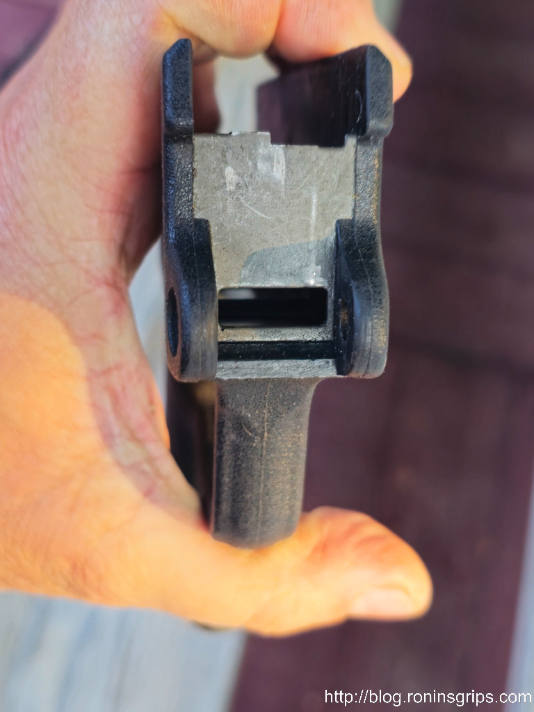
The other measurement you need to find out is how deep to drill the countersink hole – the recession in the grip where the head sits on the left side (looking down) and the end with the wire retainer protrudes on the right. You may well find that the two measures are different again.
What you need to ensure is that the rear takedown pin’s working distance can span from the left side to the right side. The working distance of a takedown pin is the measured length from just under the head to just before the retaining wire comes out of it. The pin that sticks out of the other end of your calpers is for measuring depth. There are also far more accurate tools purpose-built for measuring depth also.
When you do you plan your countersinks, you need the distance the pin spans to look something like this:
Minimum depth of countersink = outside grip dimension – takedown pin working length
Now how you make that happen is up to you. For example, if you need to remove 3mm and want to split it to 1.5-1.6mm per side – that’s fine. Ideally, you want the pin to stick out far enough on the right side so the wire retainer can pop up and help hold the pin in place.
Milling the Countersink & Pin Holes
These operations require end mills that can make plunge cuts – meaning the end mil has cutting surfaces at the bottom and not just the sides. These are sometimes called “center cutting” end mills also. I would also recommend four flutes for a smooth finish.
The actual countersink diameter is 9.5mm but if you don’t have access to that, a 10mm end mill will work also. The takedown pin hole is 6mm. How much you want to spend on the quality of the mills is up to you. The polymer will not wear the 9.5-10mm bit much but the 6mm bit will need to keep its edge long enought to cut through the steel reinforcement on both sides. I’d recommend the6mm be either cobalt or carbide and not just high speed steel – or at least not cheap high speed steel.
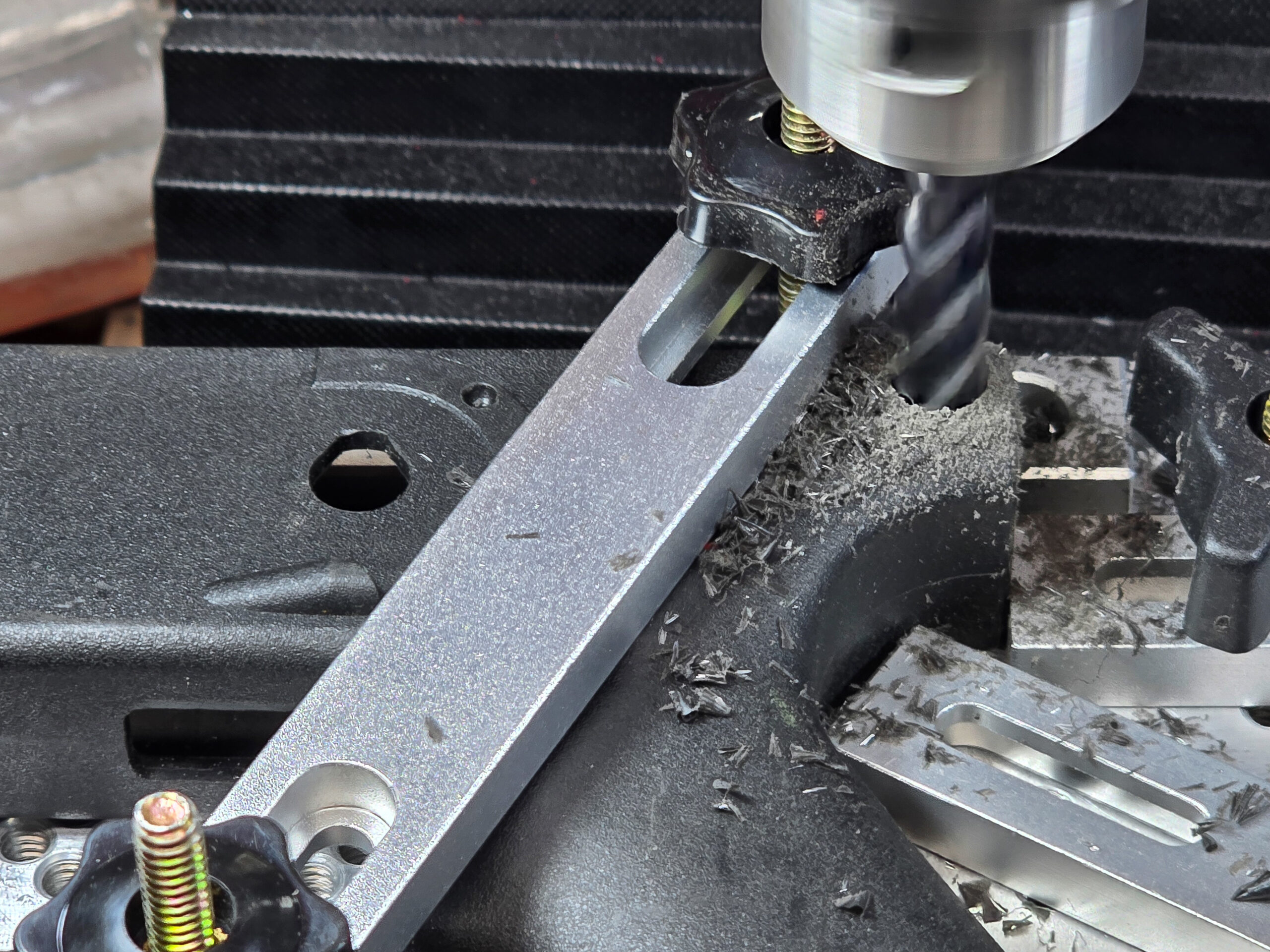
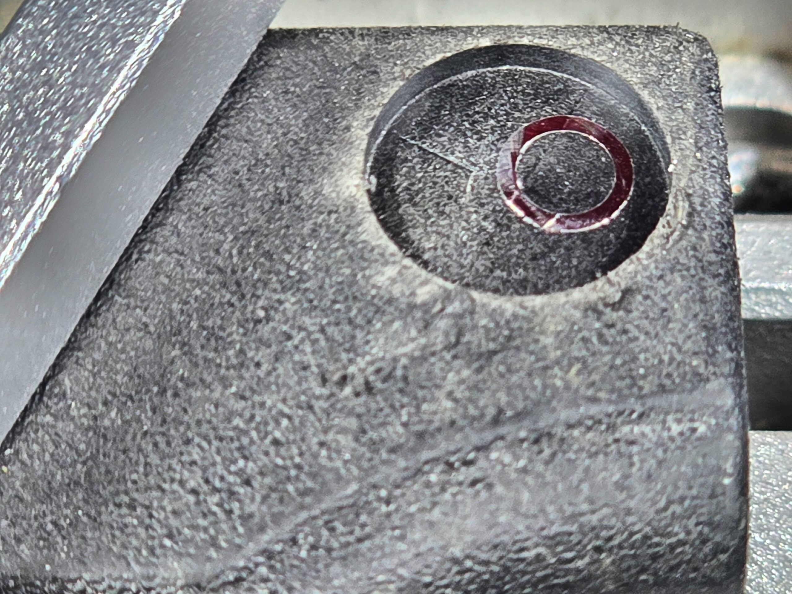
If you are wondering why not use a 6mm drill bit, it is because you will likely encounter a hole in the reinforcing plate that was cast into the grip during injection molding. A drill bit will hit that hole and want to yank the workpiece upwards as the edge of the opened hole rides up the flute and makes a mess. An end mill doing a plunge cut will not have this problem as it will cut off the open circle’s ends.
So, yes, you can use a drill press but what is incredibly important is that you have the workpiece held firmly so you need to clamp it down.
Make a wood or plastic insert that you can put in the top of the grip to keep it from deforming when clamped and then milledd/drilled. If the grip moves at all, your new grip will be ruined.
Honestly, 99% of my challenge was figuring out how to securely hold the grips so they wouldn’t move and also not introduce angles/canting, etc. I’m still working on improving this as the overwhelming amount of my defects are caused by unintended workpiece movement.
You need to locate your new hole centers and then set up your milling machine or drill press to do the cuts. You need to figure out what works best for you. If you have digital read outs (DROs) then you probably didn’t need to read this blog post. If you are new to this, locate the hole center and mark the hole with a very fine point then use either a small drill bit or hole finder to center your machine on the hole.
To get the depth you need on the countersink, either use the features of your machine if it has some form of depth indicator or wrap a piece of tape at whatever limit you need and stop when you reach it.
I would highly recommend you do the countersink cut and then the hole cut on each side before you move on to the next. In other words, do a side at a time before you move the workpiece.
If you are wondering why I am not mentioning how to locate and cut the front pin holes, it’s because you don’t really need them if your weapon uses a shelf, which most current HK grips do. For example, the Magpul SL grip does not have the front holes. The way the polymer is formed, you would likely need a longer pin and it’s not going to give you a better connection. The front plate of the grip is shoved against the shelf by whatever you have on the end of the weapon and the top rear pin keeps the grip from swinging down – that’s really all that you need.
Summary
You can do the conversion or buy our ready to go grips. You may need to do some final fitting but we’ve done the hard parts. If you’re interested, click here to go to our HK Grips page.
I hope this helps you out,
Please share the link on Facebook, Forums, with colleagues, etc. Your support is much appreciated and if you have any feedback, please email us in**@*********ps.com. If you’d like to request a report or order a reprint, please click here for the corresponding page to open in new tab.