In September 2021, I bought my first new truck – a 2021 Ram 2500 Tradesman. Something about it being straight forward without a ton of bells and whistles appealed to me and I managed to buy it – I’ll be making payments for four more years 🙂 At any rate, there were a number of things I did to customize it more to my needs – one area was lighting. For whatever reason, Dodge went cheap and used halogen bulbs and they were anemic.
The first thing I did was to buy a set of Lasfit LED replacement bulbs and upgraded the high beams. Wow – what a difference. I considered doing the low beams too but changed my mind. First, I could not get my hands into the low beam housings to make the swap without taking more of the truck apart. Second, after seeing how bright the high beams were, I was worried about blinding oncoming drivers so I just settled and left the low beams alone. I don’t really regret it – when I am on country roads at night and turn on the high beams, wow – there’s a HUGE difference.
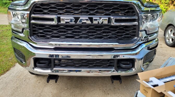
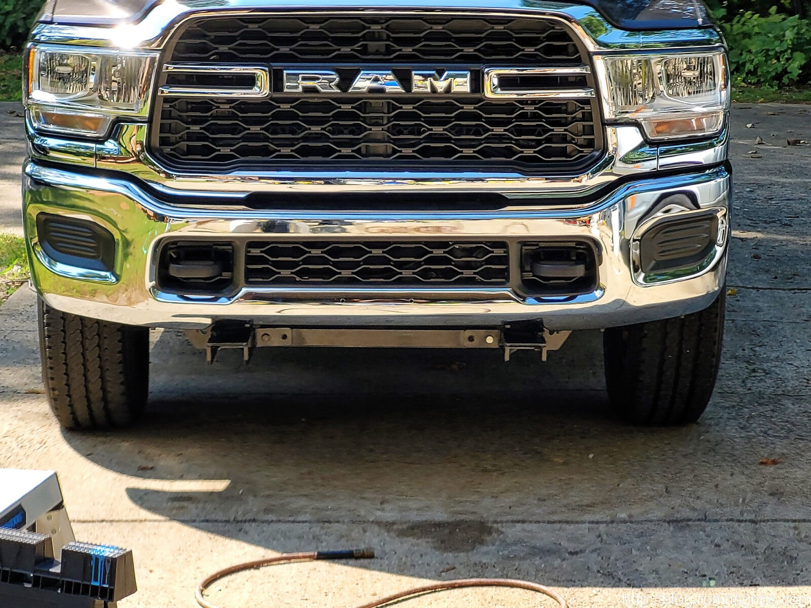
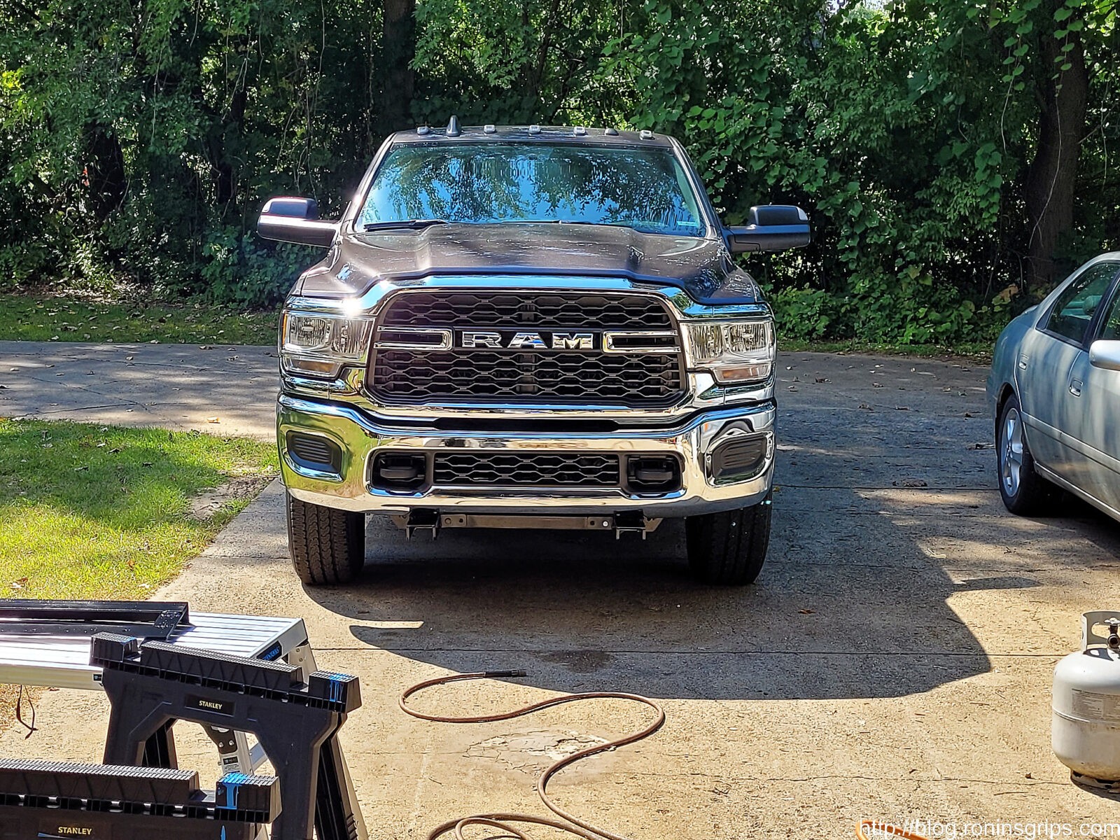
Until you drive rural farm roads at night or go off-road, you don’t really appreciate having good lights. The new high beams were good but I wanted even better – I really wanted a light bar but I wanted it without making a ton of alterations to the truck. My 2500 has a cap and no roll bar or headache bar to mount on so that left the bumper, the A-frame or some form of roof mount. I did some thinking and decided to go with a non-traditional approach – I would mount the light bar behind the lower grill and add a yellow light bar for fog and snow below it angled downwards.
Legal Disclaimer: The LED light bars are rated for off-road use only. Be considerate and don’t blind other drivers. Not to mention you would likely get a ticket operating these on public roads.
What LEDs To Use
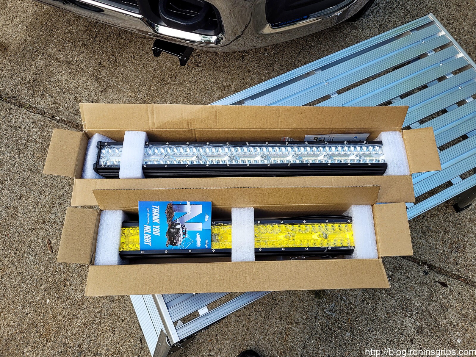
Okay, I am short on funds right now and needed good enough parts. I’ve had pretty good luck with Nilight LED bars that you can get really good pricing on from Amazon plus they also have wiring harnesses with relays that you can use.
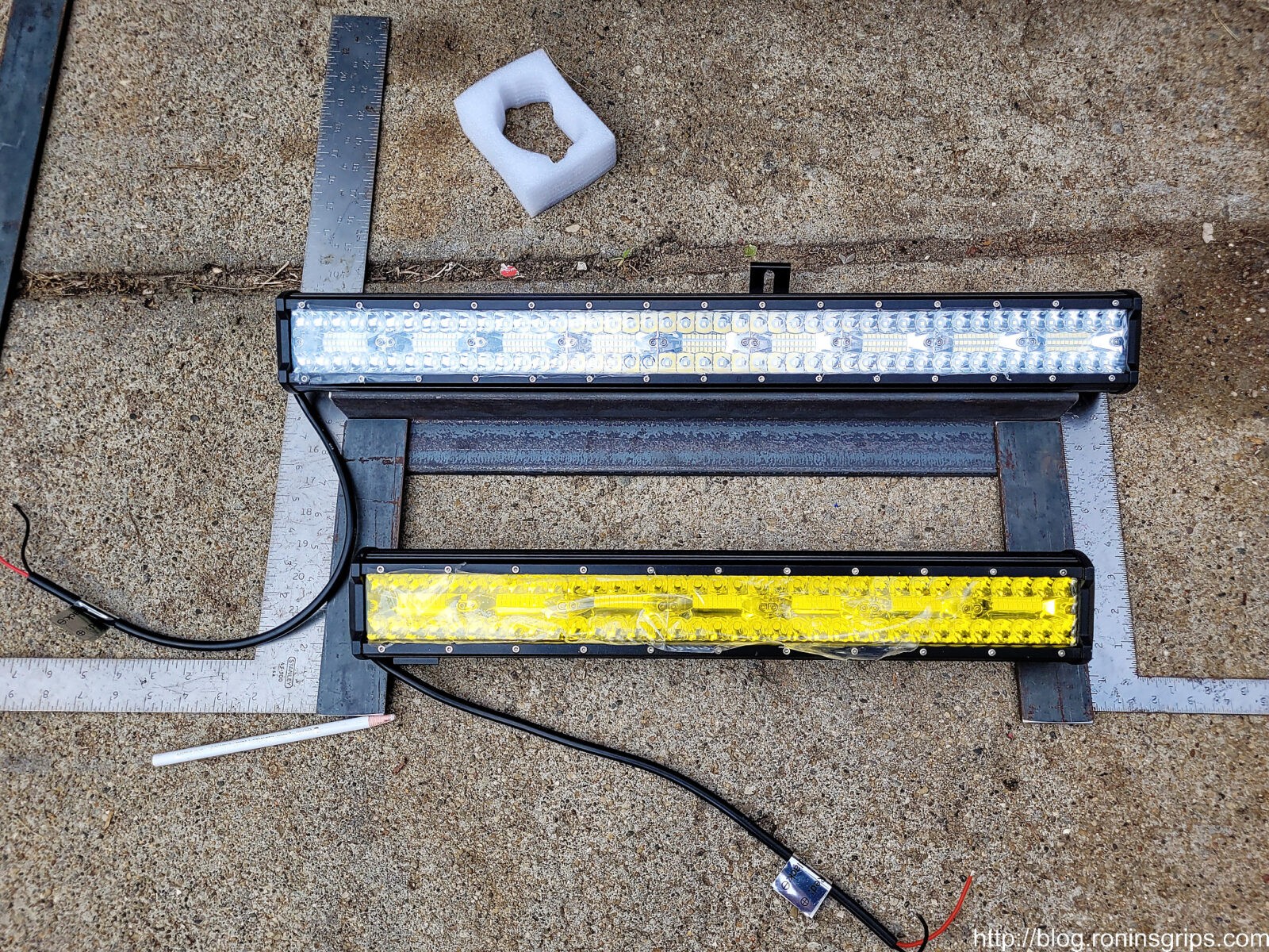
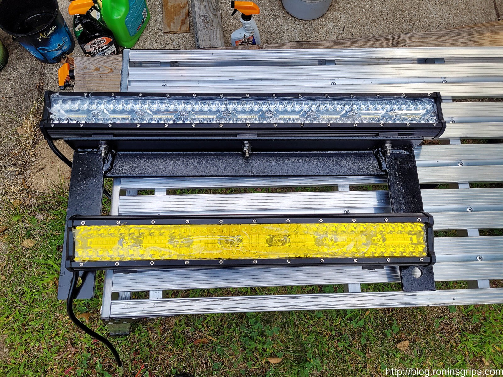
I wanted to fill the lower bracket from left to right so that meant about a 26″ light bar. To project the light both far and wide, I bought a triple row unit that combines flood and spot lighting.
For the amber LED, the biggest they had was 20″. I didn’t really want massive light from it because it is for snow and rain. In case you didn’t know, amber/yellow lighting is preferred for fog lights because that wavelength of light does a better job penetrating and letting you see objects in those conditions.
We were in the Smoky Mountains near Wears Valley between Pigeon Forge and Townsend a few years back trying to get to a cabin during heavy rain at night. Our old Highlander had so-so white fog lights that were better than nothing but I became a believer after that. Tons of white light just bounces back at you in rain, fog and snow. Go with amber lights.
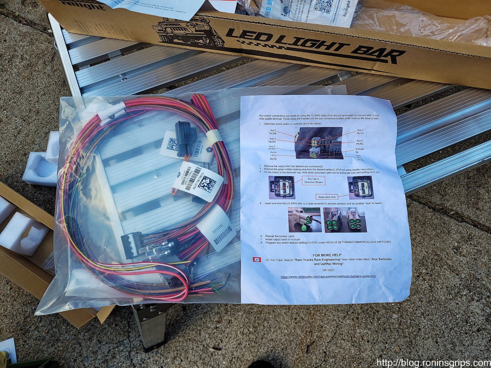
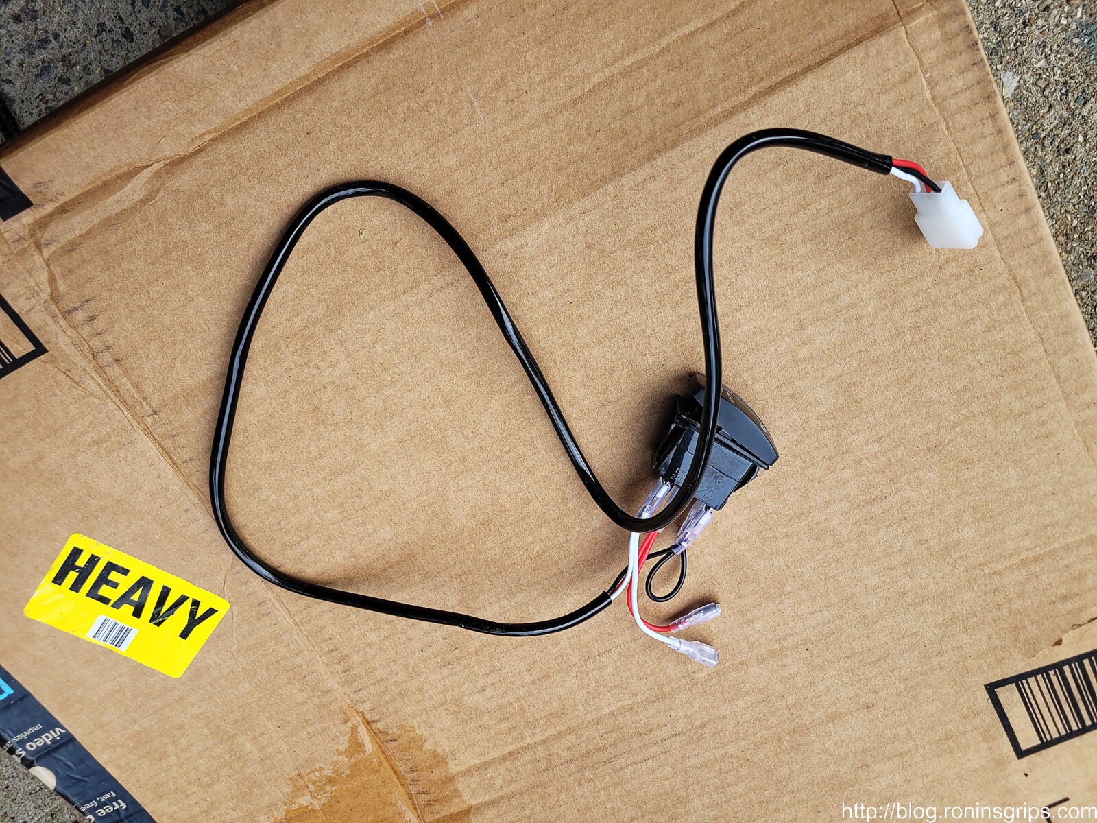
In terms of the wiring harnesses, I bought two 14 gauge Nilight sets. I planned to remove their switch and plug into the Ram upfitter switches. The upfitter switches are an option and a truck is prewired with a number of access ports to let you plug in things like lights, pumps, etc. If your truck doesn’t have upfitter switches then just run their switches into your cab and mount them on the dash. I’ve used 3-4 Nilight light bars and switches over the years and none have failed on me – they look good too because they light up when turned on.
When it comes to wiring lights, I prefer to use relays when possible. This allows you to use a switch with fairly low amperage that then powers the relay and closes the switch that then feeds current from the battery through a thicker gauge wire. This avoids choking the power running too thin long wire to the switch and back. When your lights are properly powered, they will produce their maximum light is what it boils down to.
Designing the Bracket
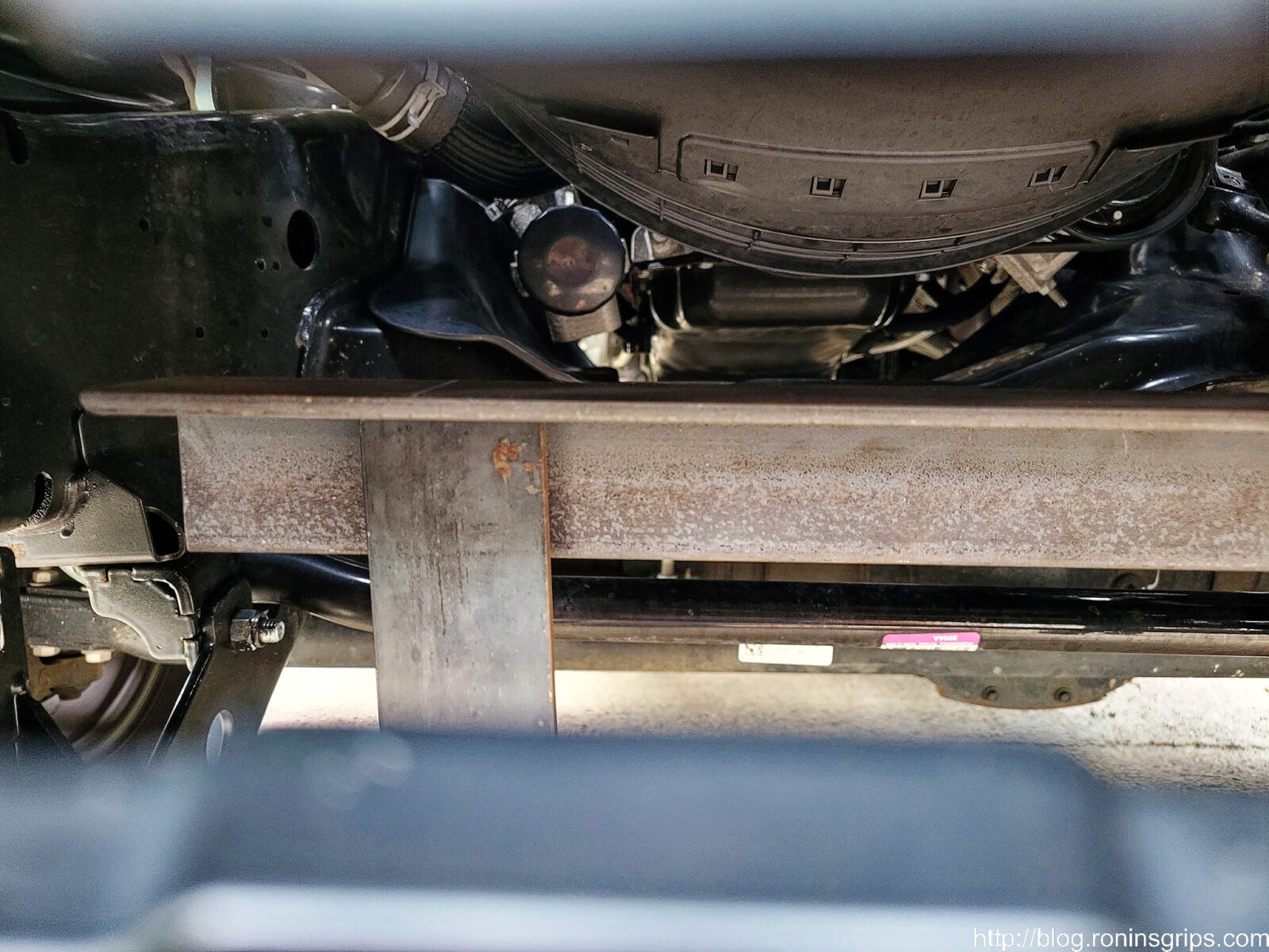
Sticking with not wanting to alter the truck, I wanted to bolt the lights to a bracket and then the bracket to the truck. Since the truck was relatively new and not rusted like crazing, I had tons of potential bolts to use – I could have secured the bracket to the bolts of the tow hooks for example. What really caught my eye was the subframe for my Western Pro Plow 2. I’m a big Western plow fan – my dad had one when I was growing up and while I’ve had others – notably a Meyer and a SuperPlow – I still liked Westerns.
To mount the plow, Western creates bolt on sub frames that will connect to a given truck and then there are receivers that the plow connects to. Part of the sub frame is a 2″ x 1/4″ thick cross member that is secured by four bolts – two on each side. That was perfect. The inside bolts were on about 20″ centers. I would connect the bracket to that and go up with a cross member and a top shelf of angled steel. The material would be 1/4″ hot rolled mild steel – why? Because I didn’t want the bracket to bend or stress crack over time from the wind hitting the lights. On one hand, I figured the aerodynamics around the truck would stop some of the air flow but on the other, I’d seen guys in the past run big old school KC Daylighters on cheap light bars and they broke. So, yeah, I overbuilt the heck out of it.
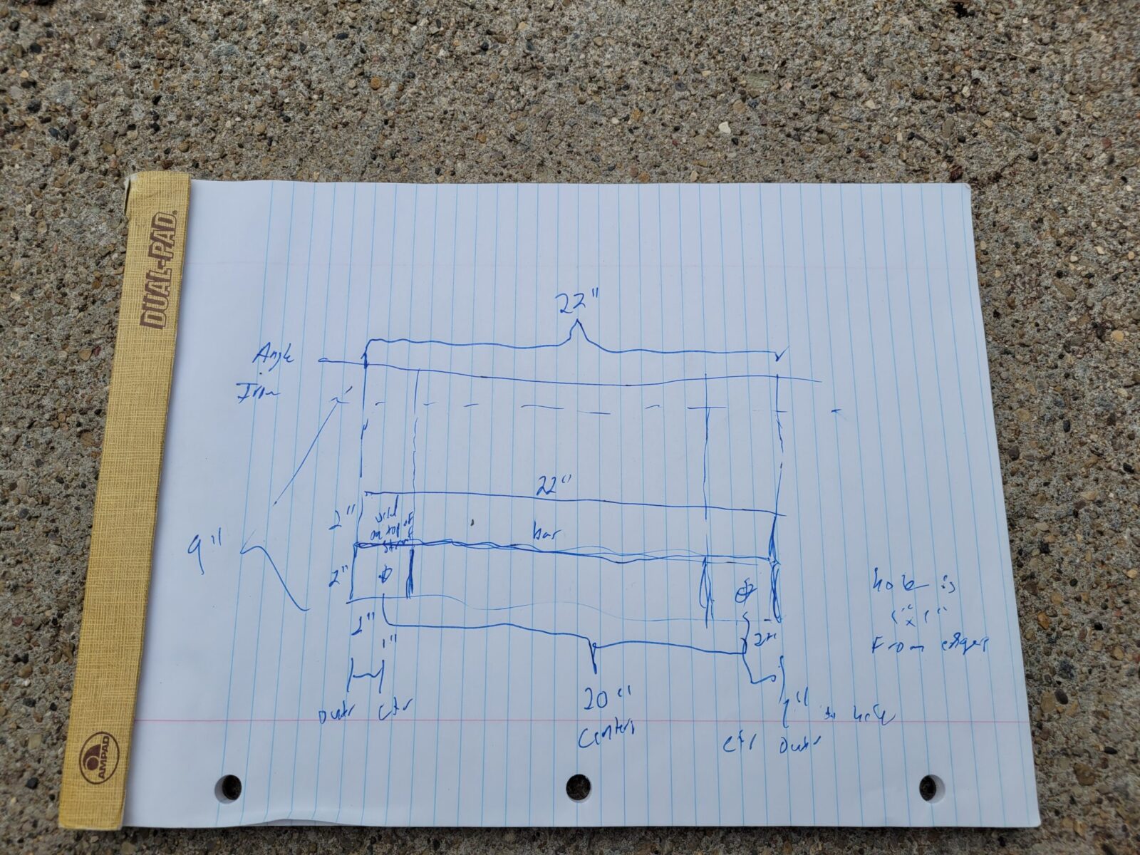
I credit junior high shop class and the instructor, Mr. Tack, with teaching me the benefit of sketching a layout before starting work. Over the years, I’ve learned to sketch, mock up, and test fit before finalizing stuff. With that in mind, I sketched the bracket with pin and paper – young people will certainly think this is from the stone age but it works for me.
This super low-tech sketch was me thinking through what I wanted to do. It all began with knowing the grill’s hole was 26″, the distance between hole centers of the Western plow sub-frame was 20″ and I had to cut a upright pieces about 9″ tall.
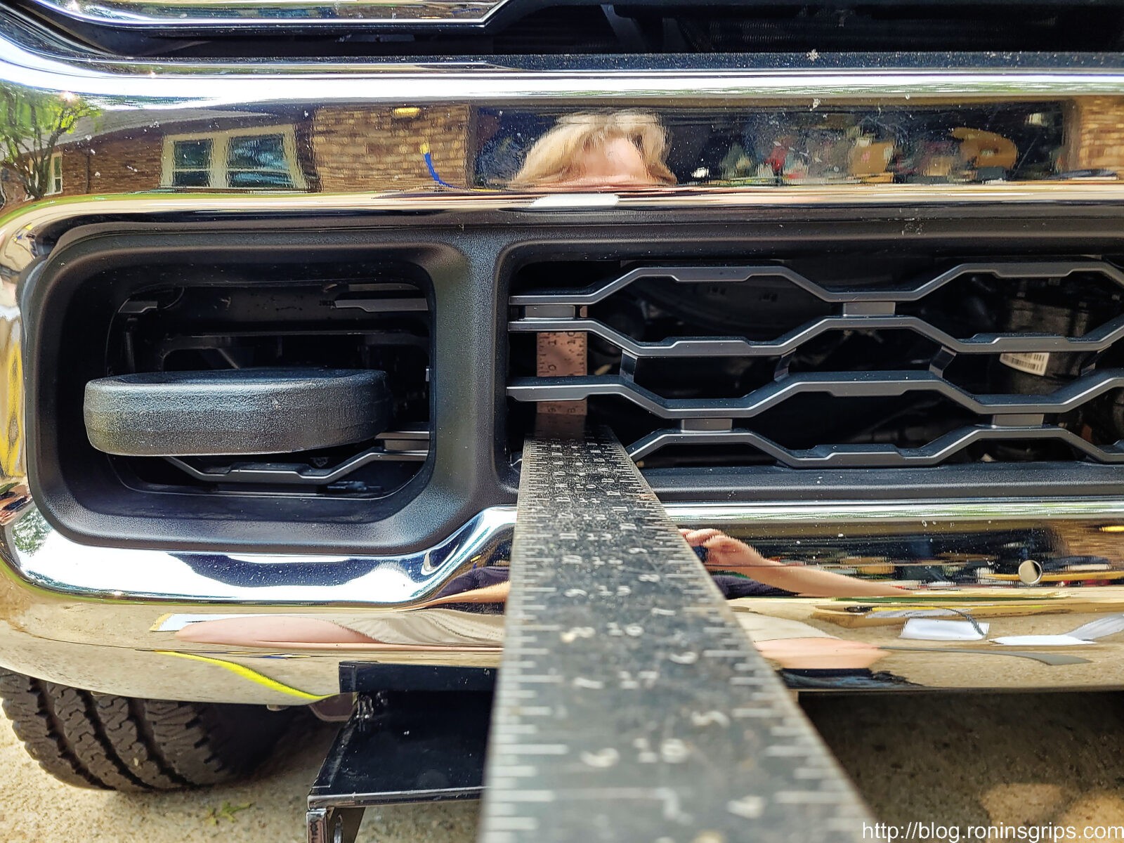
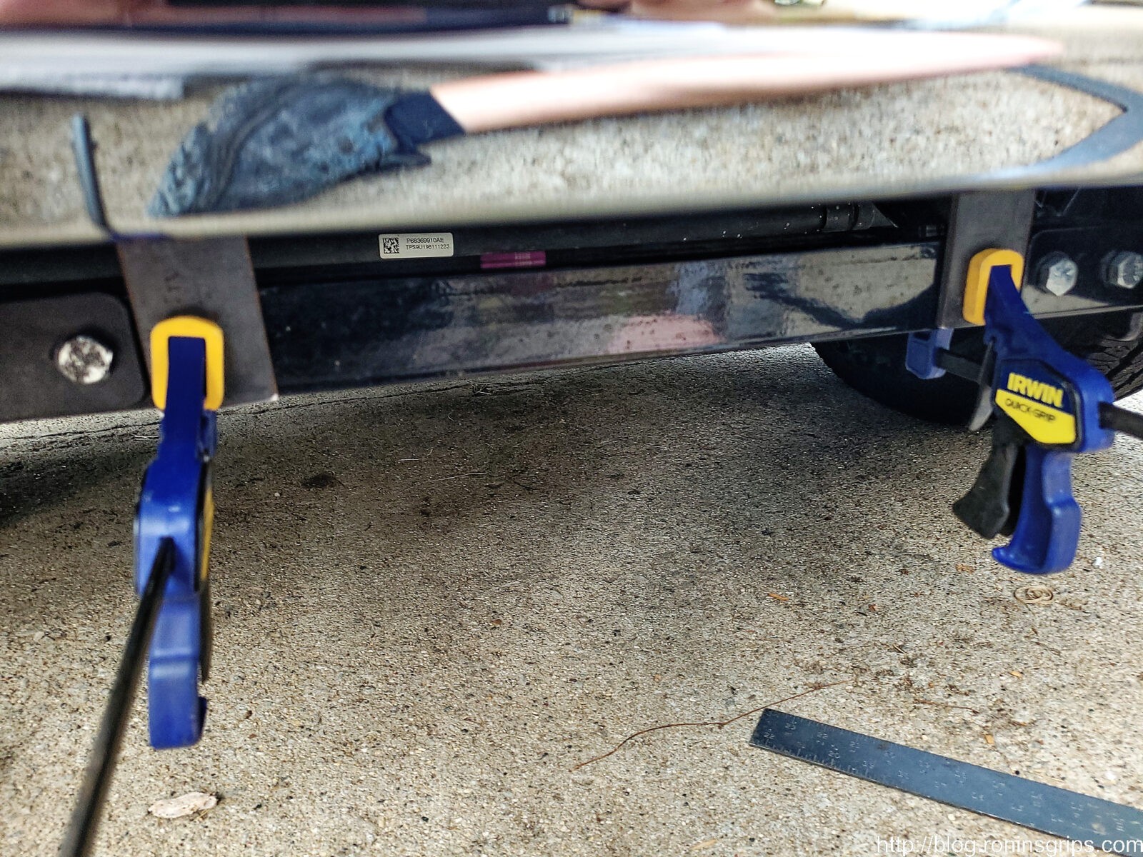
I figured out the vertical by clamping a steel square rule to the plow’s sub-frame and then ran a piece of steel through the grill to measure the height where the two met.
Before You Start!
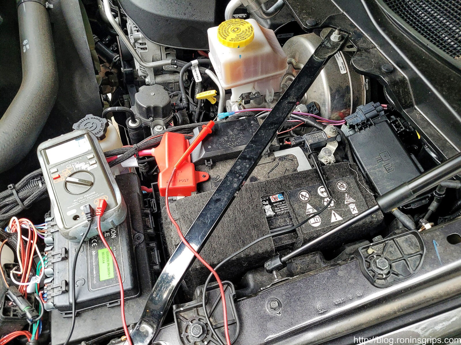
When it comes to lighting in general, trust but verify. Before you do anything else, take the lights out of the boxes and connect them direct tot he battery to make sure they work.
Each light bar has a short lead. You need to either touch them directly to the battery and make sure the bar turns on or use some short jumper cables. I clipped the negative to the battery and bridged the positive to the battery using a remote starter switch that I had handy. Really, you can use just about any short length of wire to make the connections and make sure they turn on – quick and dirty is all you need.
Fabricating the Bracket
With the design roughed out, the next step was to begin cutting out the pieces of steel. Over the years, I’ve learned that I am better off to work on a section at a time vs. cutting everything at once. This way, if I make a mistake or need to adjust the design, it’s easier. I tend to find design mistakes earlier on this way.
I cut two 9″ pieces of the 2″x1//4″ bar stock and clamped them to the frame. Note they are not in the final position. I planned to pull the inside set of bolts, drill holes in the bar stock and mount them there. What this let me do was to test if I had the height right.
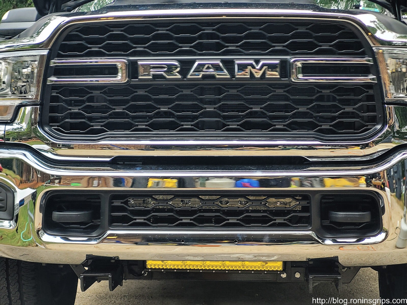
With the uprights clamped in place, I then cut the 2″x1/4″ angle iron to a length of 22″. I did 22 because I wanted plenty of material surrounding the bolt holes that I would drill but also had to be mindful that I would clear the outer bolts of the sub-frame’s cross member. I then set the LED light bar on this, took a step back and looked to see if I had it right and thought it looked good enough to proceed. Note, this puts the LED light bar close to the top of the bumper hole’s top edge.
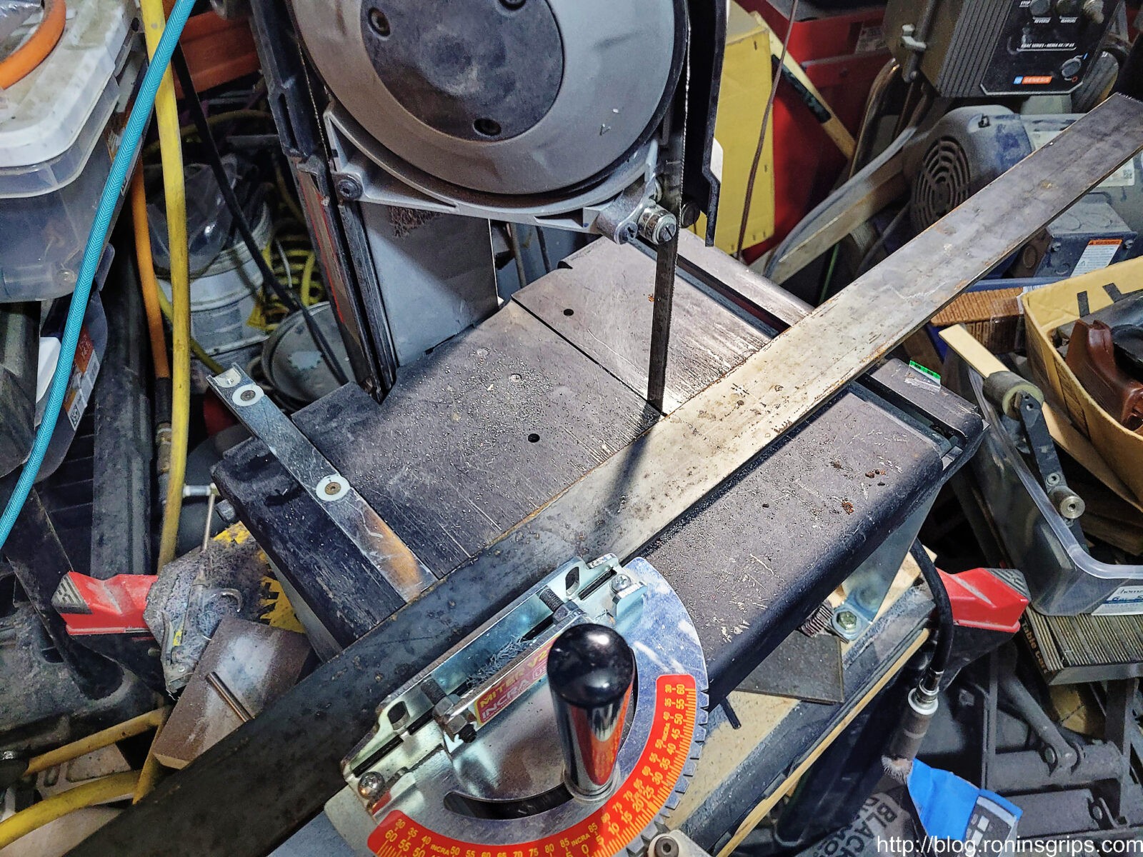
Armed with the dimensions confirmed, I then cut out the horizontal cross member that would hold the amber fog light. This is my SWAG Offroad table holding a Milwaukee Portaband. I use this all of the time for cutting steel and composites in my small shop.
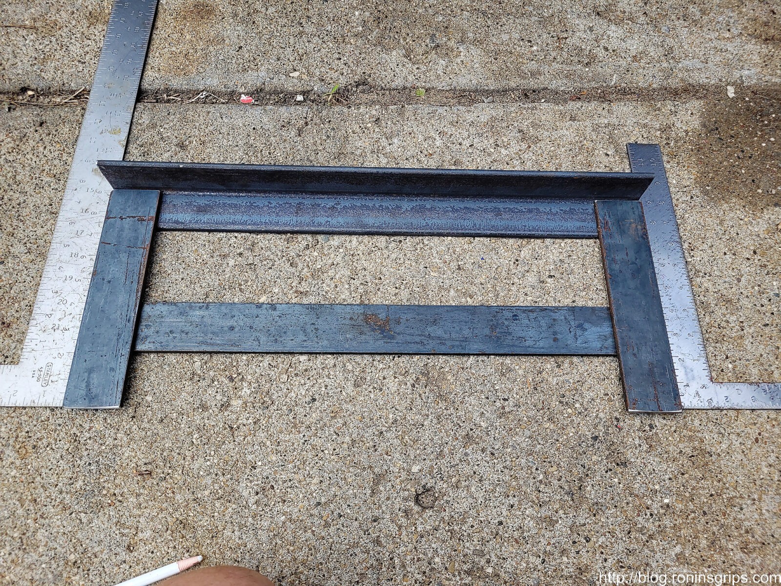
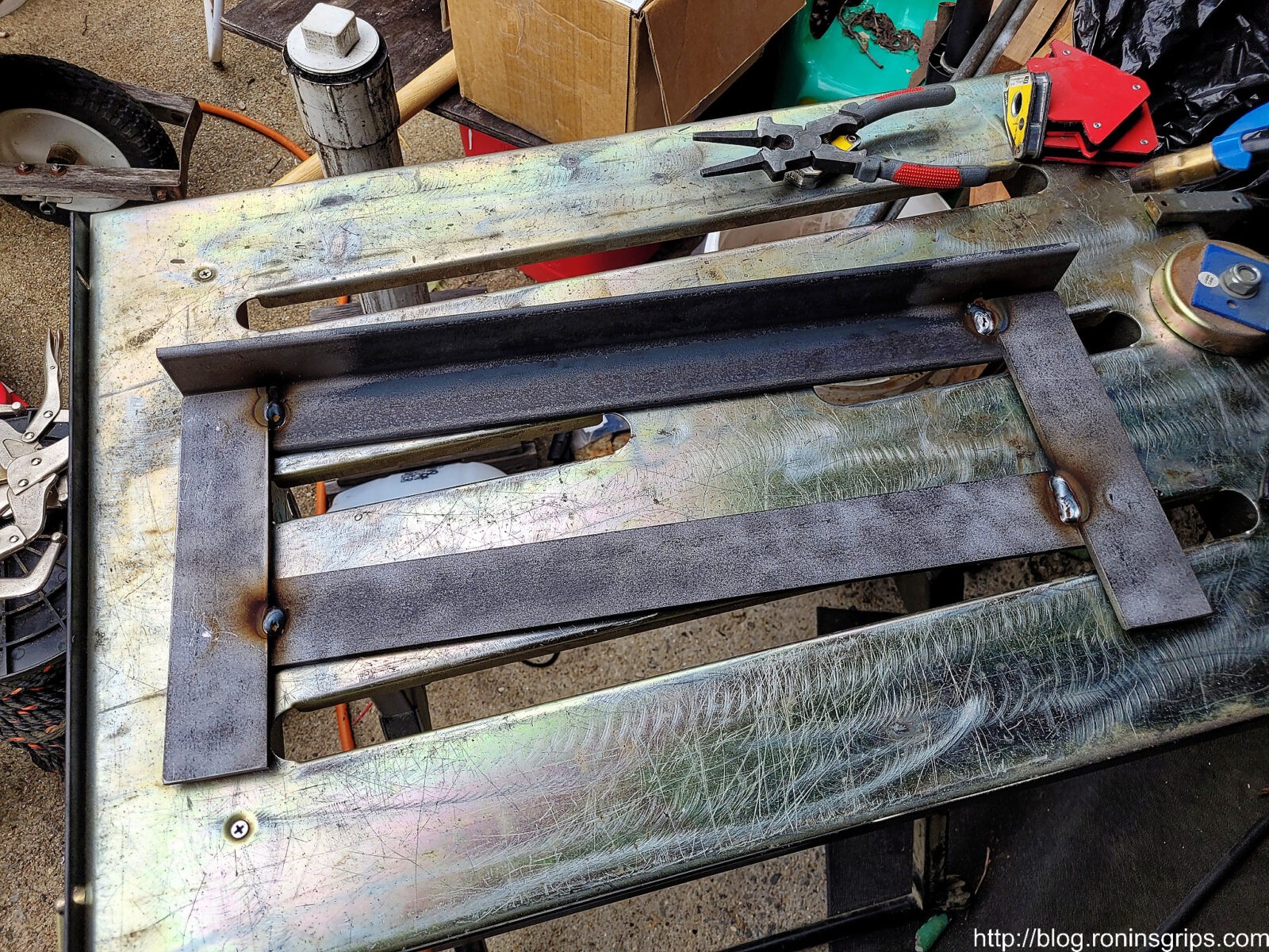
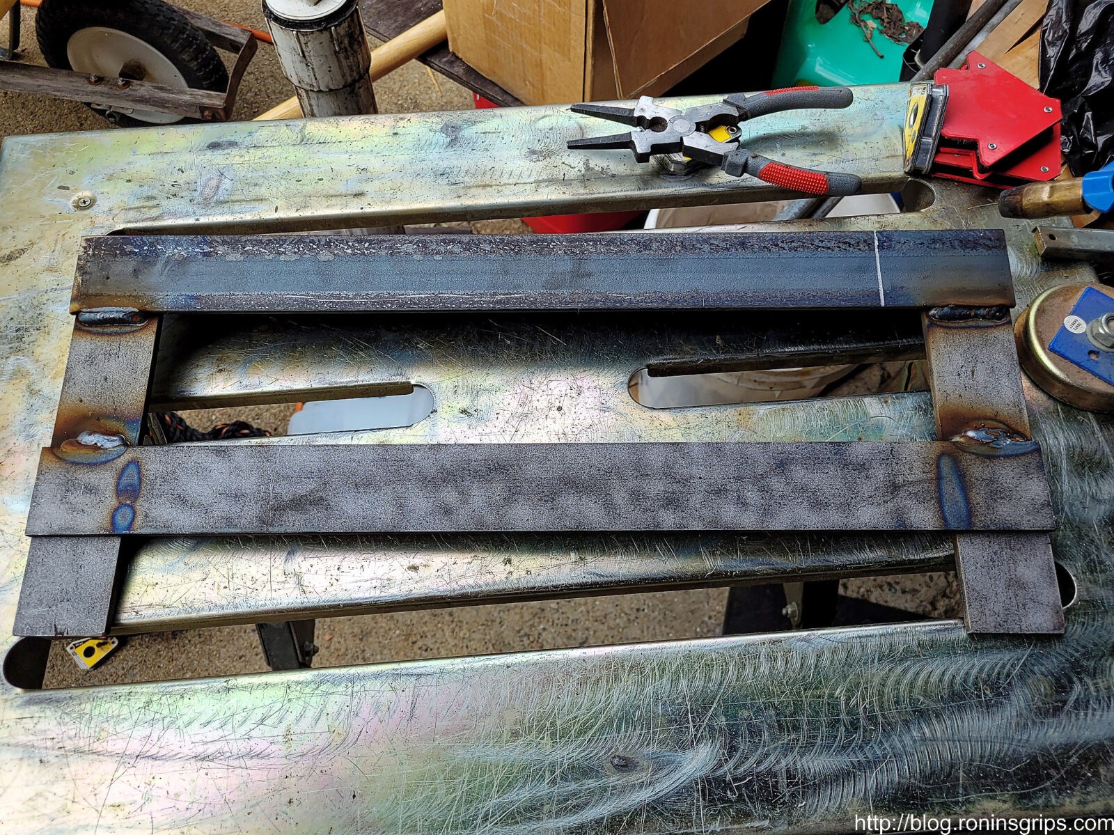
This is the mocked up bracket. I confirmed the dimensions one more time. Note, I planned it this way because with the cross member to the back, it will be sitting just fraction of an inch above the plow sub-frame’s cross member. I wanted the fog lights to be low . I debated about using a piece of angle iron for that lower portion but at some point design overkill isn’t worth it. Also, I welded the bracket together. If you prefer, you could bolt them together also.
Part of the mockup was to check the lights. Note, I did not drill the mounting holes until after welding in case I wanted to adjust something.
I did remember to take a quick photo while cleaning up the steel prior to welding. Note, if you want good welds, sand, grind or abrasive blast down to the shiny silver steel. The grey coating on the metal is known as mill slag which will contaminate your welds and the brown is rust which will do the same. I didn’t bother getting all of the steel equally clean. I did make a quick pass through everything so the paint would have a good surface to adhere to but I really focused my cleaning on where the welds would be.
Welding the Bracket
I used my Miller Millermatic 211 MIG running 75/25 shielding gas and .030 wire. I set the thickness to 1/4″ and let the machine figure things out. I bought this machine years ago and it really does a great job for me – most of my work is light fabrication anyways with thicknesses usually at or under 3/8″ thick and relatively short weld times.
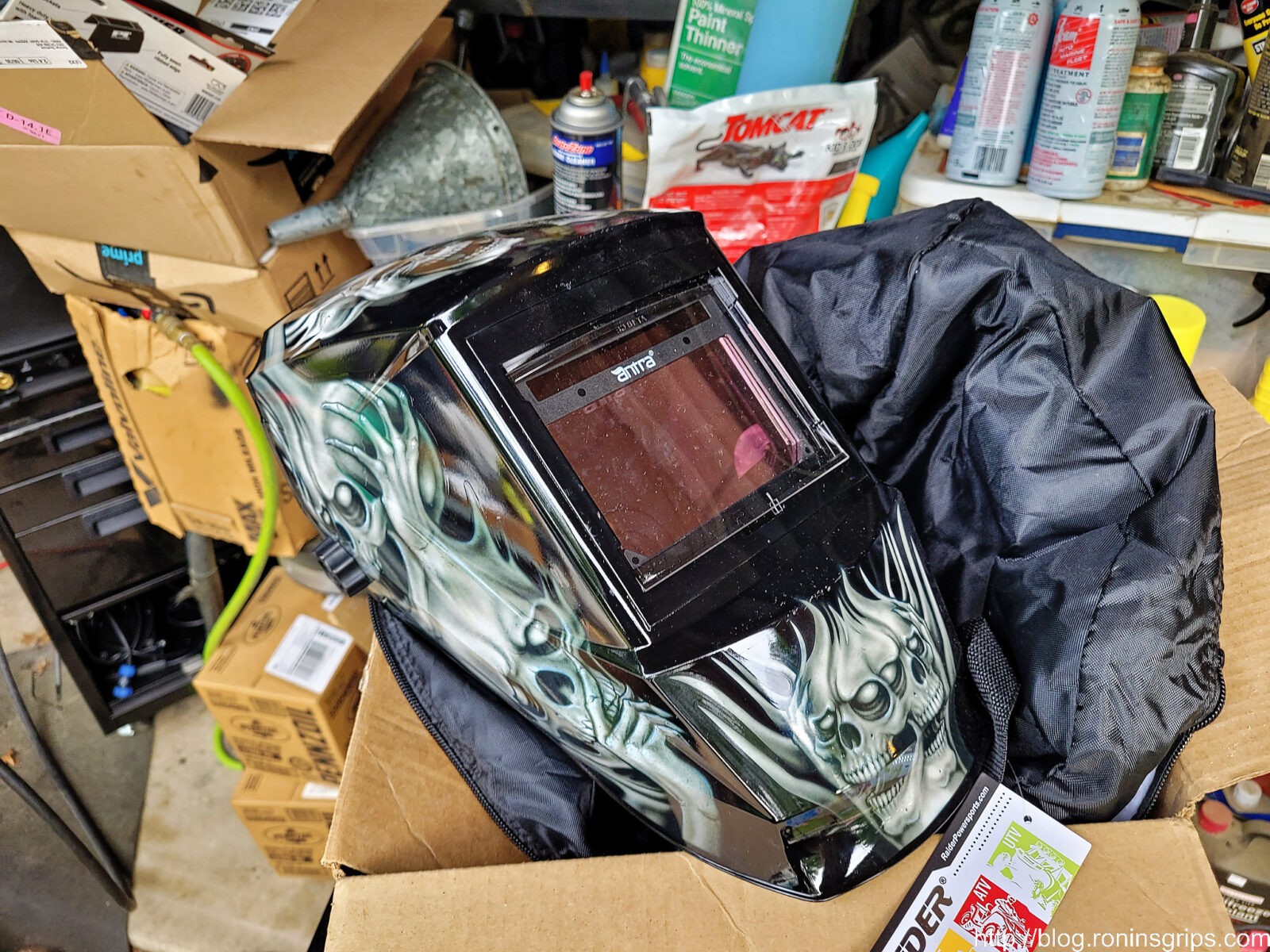
This past summer I bought a new Antra welding helmet with a large view port. I had an older Antra helmet that I bought in 2014 that still works it just looks very used. The cool skull graphics and larger viewing area tipped me to buying a new one. I like Antra helmets – not only do they work well but they also come with spare lens protectors.
I did some quick tack welds with my Miler MIG. The purpose of small welds like these is to get the assembly basically held together so things don’t move plus you can take and confirm the fitment one more time — which is what I did. If a mistake was made or something shifted, you could grind the small tack weld off. The photo doesn’t show to but I clamped everything together very securely to make sure things didn’t move. It really pays off to make sure everything is laid out tight and clamped together before you weld. I’ve had stuff get messed up so many times over the years that I am now very careful.
With everything confirmed, I proceeded to weld the joints front and back. Note, do a small bead and then move to another area to weld so you don’t cause the bracket to get too hot and warp. None of these beads were done all at once. The discolorations reflect the welding on the other side.
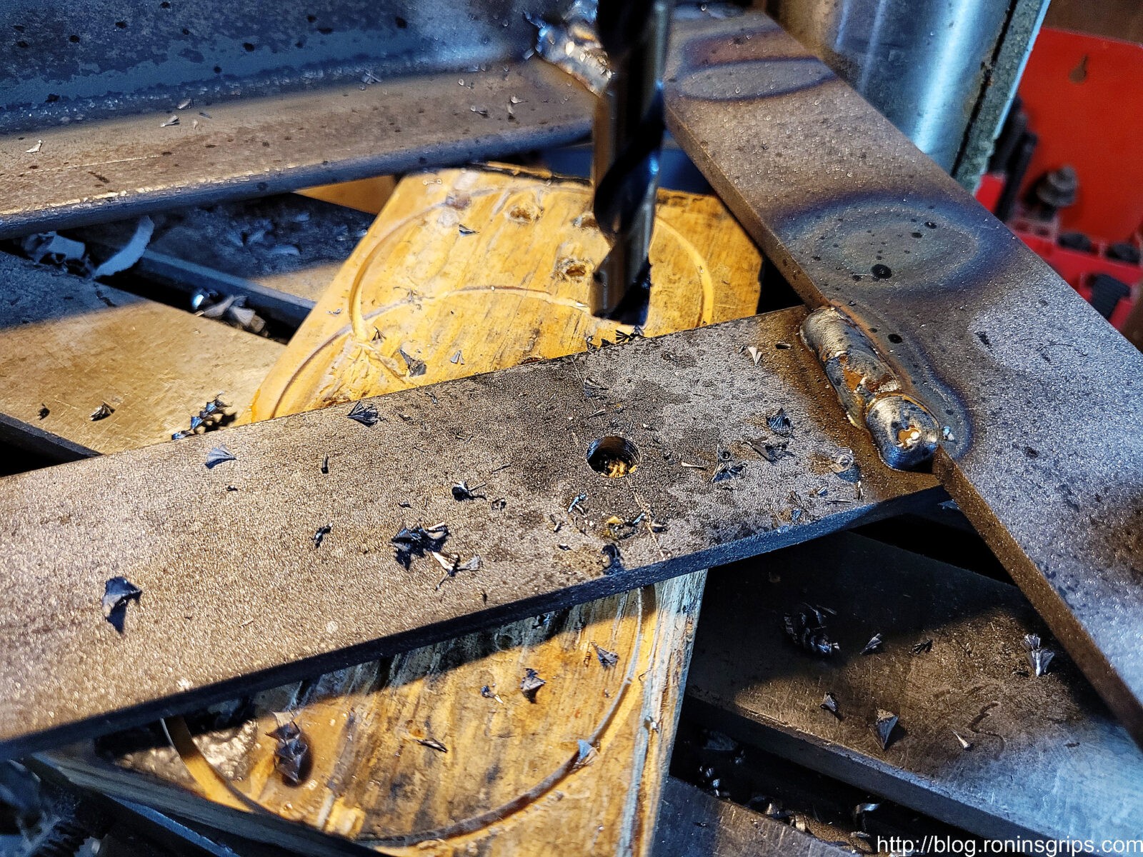
Before painting, I drilled the various mounting holes I needed for the LEDs. Note, not all have the same number of mounts – the 20″ light bar and two and the 26″ light bar had three. You can slide them all around to get the angles you want. Be sure to use cutting fluid to making cutting easier – your bits will last longer.
I like to drill the holes slightly oversized so I can wiggle the bolts around a bit if needed. I’ll own the mistake this photo shows — I forgot to drill the third hole in the middle. I fixed that later. By the way, the cross-member bolts are quite large. I used a Silver & Deming reduced shank 5/8″ bit. When bits are that big, using a drill press really helps.
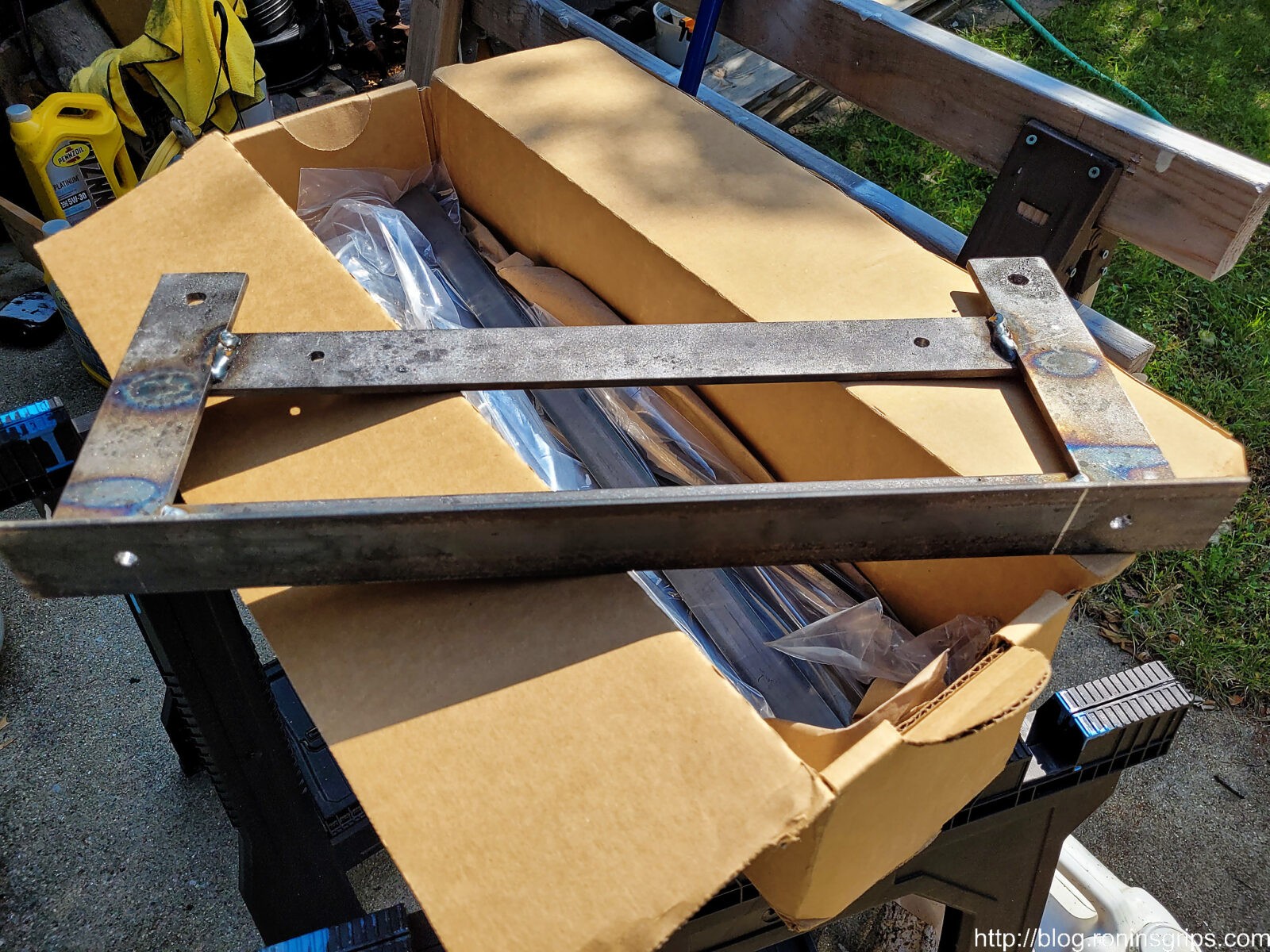
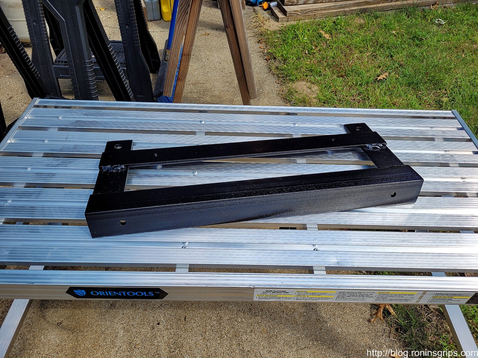
The front of the bracket has four coats of black Rustoleum all in one and the back has three. It’s impossible to stop rust in Michigan due to our salting roads in the winter but we can at least try and delay it. Yeah, still no third hole on the top yet. I don’t think I have a photo of the bracket before mounting the lights with the third hole. For all of the holes, try and make sure they are true to one another and horizontally parallel .
Before mounting the lights, I did test mount the bracket just to make sure. One interesting thing surfaced – when the tech installed the plow sub-frame, he did not true the left side. The right side is properly parallel to the ground. The left side’s bracket is clocked up a degree or two. If you look at the cross member where it bolts together you can see the left side is not true. I plan to find out what they did wrong and fix it but didn’t do so when I installed the lights.
By the way, this was not light by any means. The bracket weighed just under 12.5 pounds prior to the lights.
Mounting the Light Bars
With the bracket completed, next up was to mount the light bars. I wanted to do that and then install the whole assembly into the truck vs. installing the bracket and trying to install everything in an awkward position under the truck.
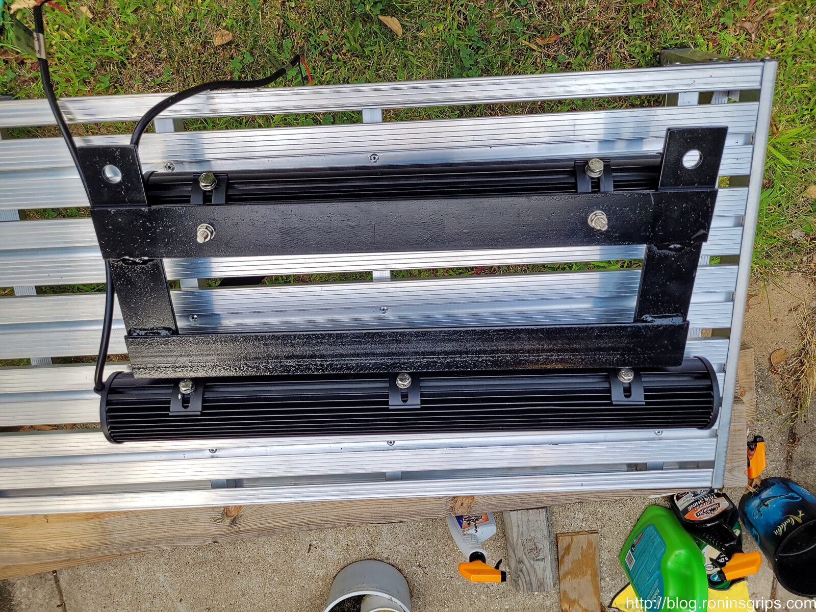
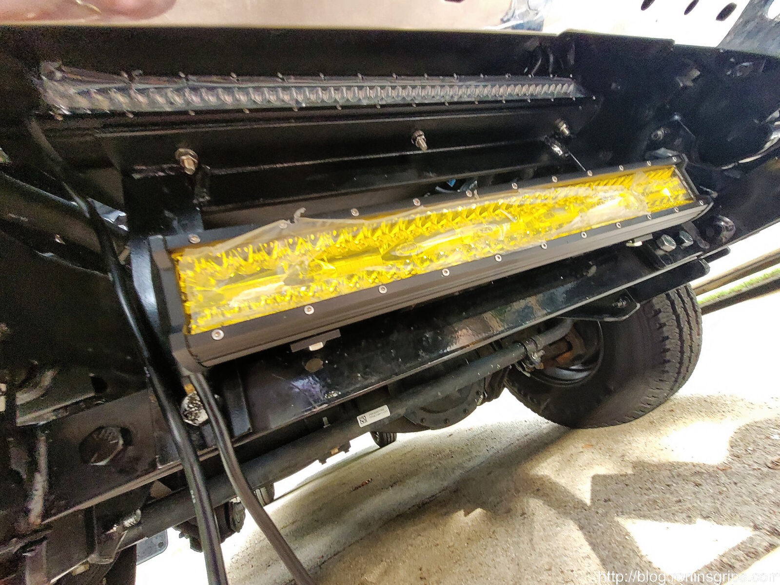
Here are the lights in their mounts. As you can see, the third bolt on the top is now in place. I did put a couple of coats of black paint in the new hole to slow down the rust. The top white LED is pointing straight ahead. The amber light is angled down as far as the bracket allows. I could have filed the slots a tad and been able to angle it down another degree or two but it turned out to be enough to keep the amber light out of the eyes of oncoming traffic.
Here’s a rear view where you can see Nilight’s brackets better. Each one has a slight arc and you have quite a bit of adjustment.
Wiring Up The Lights
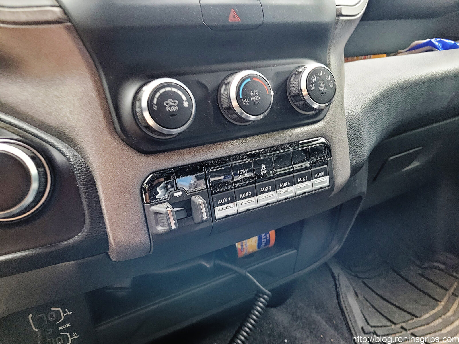
As mentioned my plan was to use the upfitter switches and I did. If you do not plan to, then use the Nilight switch. I am going to detail what I did with the upfitter wiring. Why use the upfitter switches? Personally, I think it makes for a very clean look. You have the nice integrated switches in the dash and then RAM also did the wiring out to a number of different terminal locations for you hook up accessories.
These are the upfitter switches. If you do not see something like this in your truck then you do not have that option package and can just go ahead with using a separate switch – such as the one that comes with Nilight’s wiring harness. My plan was to use Aux 1 for the 20″ amber fog light and Aux 2 for the 26″ white LED bar.
In addition to the switches you should have a bag of wires and a brief guide in a plastic bag. My bag was under my back bench when I bought the truck. You need the wiring in this kit. There are aftermarket wiring kits if you lost your’s but bottom line is that you need the wiring.
We are using two of the 12 AWG wires – the color code for Aux 1 is Pink with a dark blue line abbreviated PK/DB. The Aux 2 is Pink with a dark green line abbreviated PK/DG.
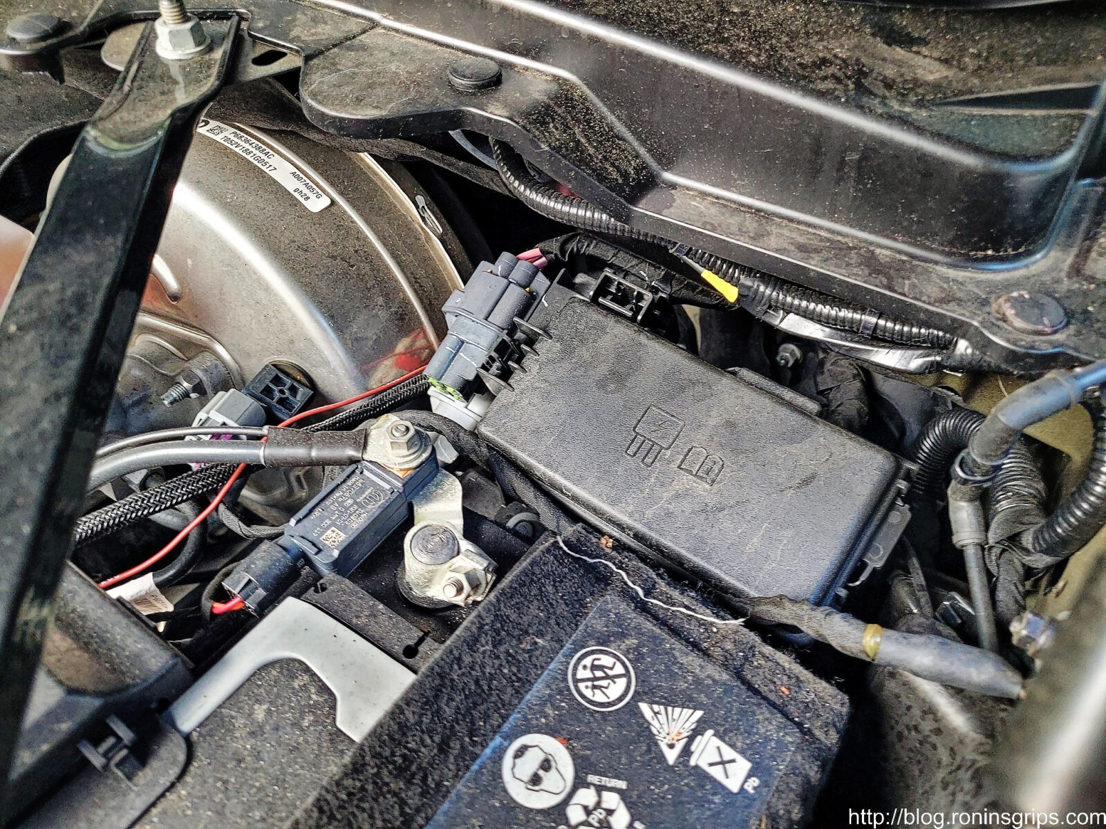
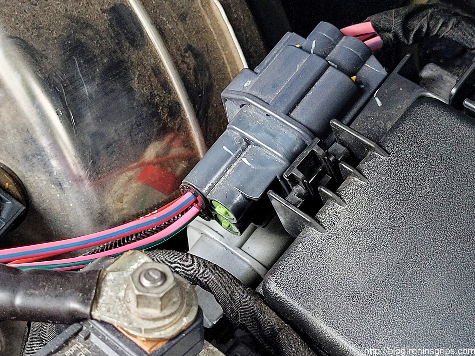
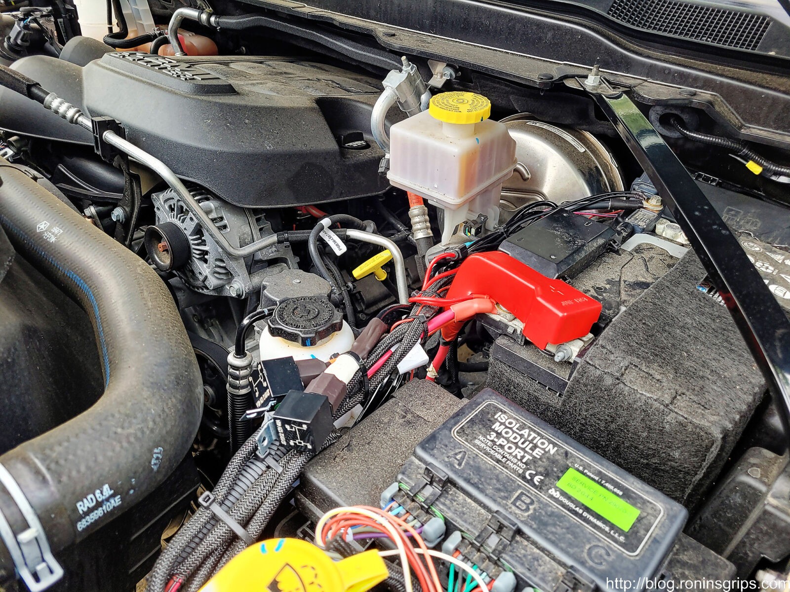
See the funny looking grey connector with the green plugs on the left side of the fuse box? That is the upfitter terminals for Aux ports 1 through 4. Aux 1 is top left. Aux 2 is bottom left. Aux 3 is top right and Aux 4 is bottom right. Now there is another grey connector block under that which we do not need.
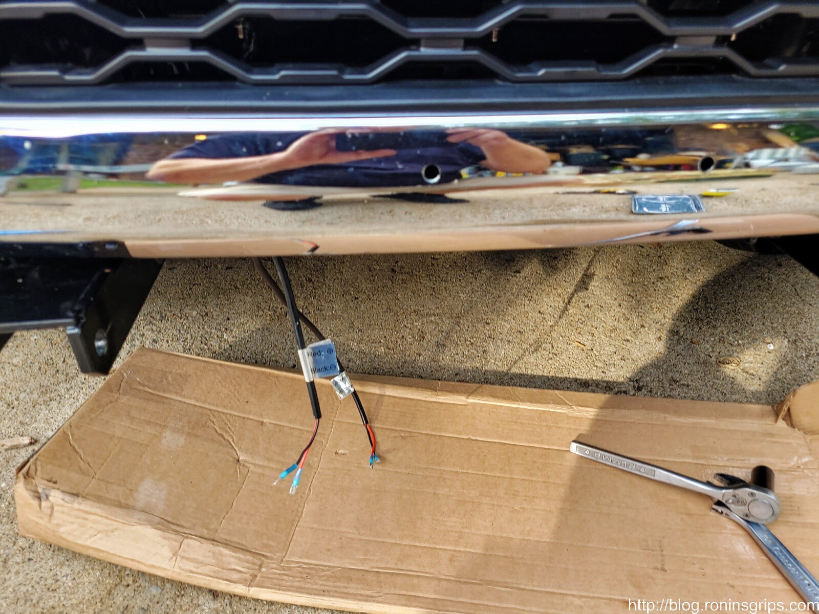
With the male spade fitting installed, I then went ahead and mounted the light bar assembly under the truck and tightened down the bolts. I put a cardboard box there because if I dropped the assembly I didn’t want to trash the paint. Thankfully, I didn’t drop it but I have fumbled stuff in the past hence the relatively soft landing zone.
Peeking up from ground level this is how things looked. I did not pull the protective lens cover film off until it was time to test the lights.
The white LED is located back from the grill. LEDs can get surprisingly hot and I didn’t want to melt the plastic. I may be losing some of the projected light being set back like that but the end result is still remarkable and I don’t have to worry about melting the grill if the truck is standing still with the LED on.
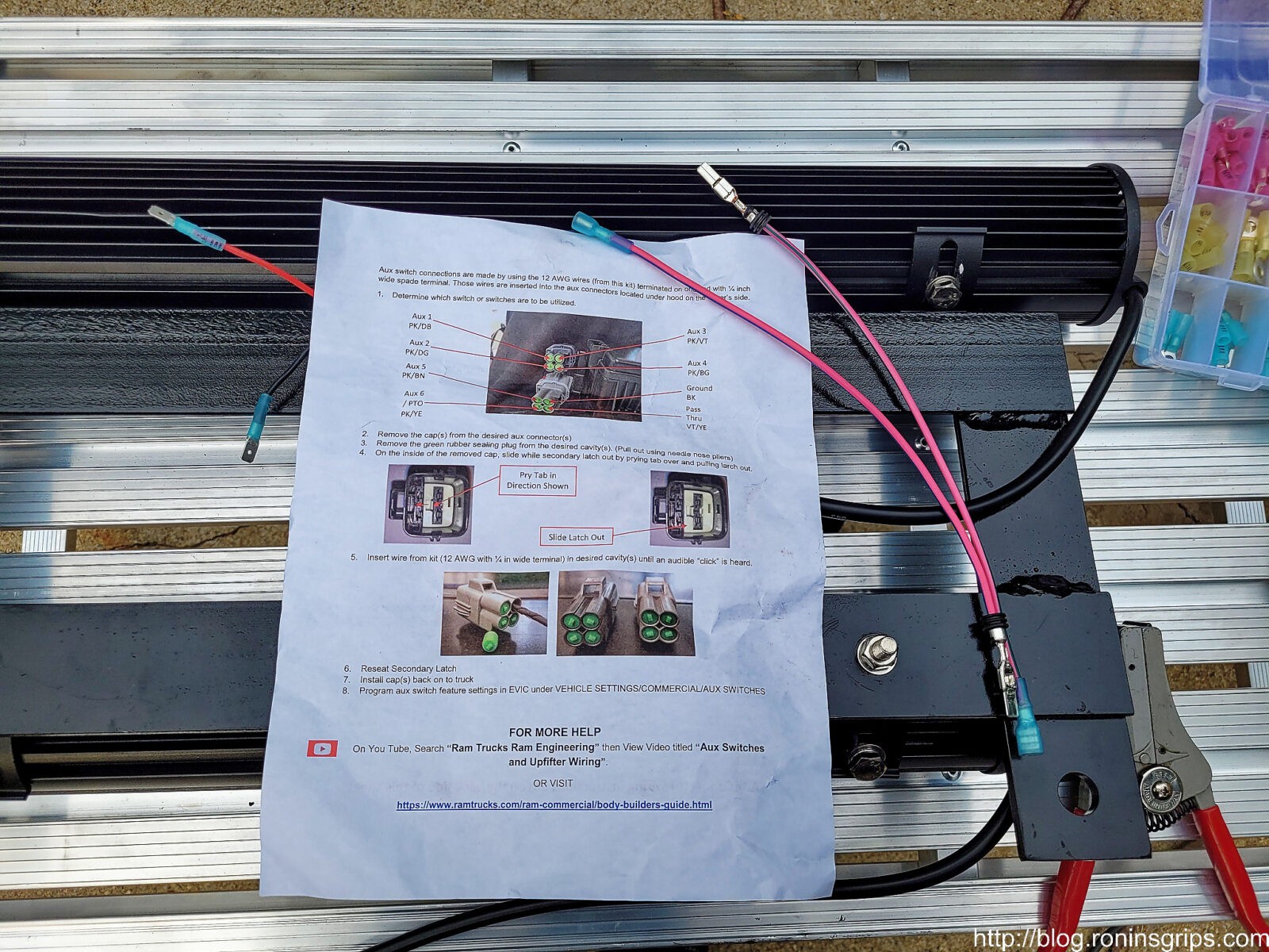
The green rubber plugs are pulled out using needle nose pliers. As you can wee, we have the pink & blue wire in the Aux 1 port and the pink and green wire in Aux 2.
Even when it comes to the upfitter switches and wiring, I wanted to make sure they worked. I turned on Aux 1 and got over 12 volts and when I turned it off, no volts. Same with Aux 2. We are using power from the Aux switches to switch relays on or off. Relays have a very low current draw so I don’t need to worry about blowing fuses relating to the upfitter wiring.
This is the modular swith portion of the Nilight wiring harness, Red is positive, Black is negative and White is switch circuit for the relay. In other words, positive comes in on red, when the switch turns on, power then goes through the white circuit, the relay switches and then the larger/heavier 14 gauge wires carry the current from the battery to each light bar. You will connect the white wire of the wiring harness to the relevant Aux pigtail lead. As mentioned, I used spade connectors but you can solder them if you wish, You will not use/need the red or black so make sure they are cut back and protected to prevent any surprises.
I trimmed the switch wire back and then zip tied everything in place so it wasn’t flopping around. One thing I did was to wrap yellow electrical tape at the base of the fog light relay so I would rapidly know which of the two it was and I wrapped white electrical tape at the base of the relay for the white 26″ bar. You want them secure so the wires don’t flex around unnecessarily and break down over time.
Testing and Results
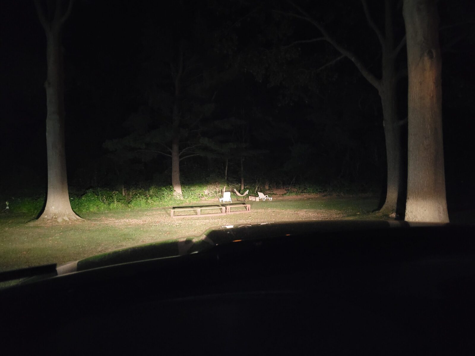
I turned the switches on and confirmed the lights work then I waited for it to get dark. The following photos are of a tree line about 40 yards from the front of the truck plus are straight out of the camera – no color changing, sharpening, etc.
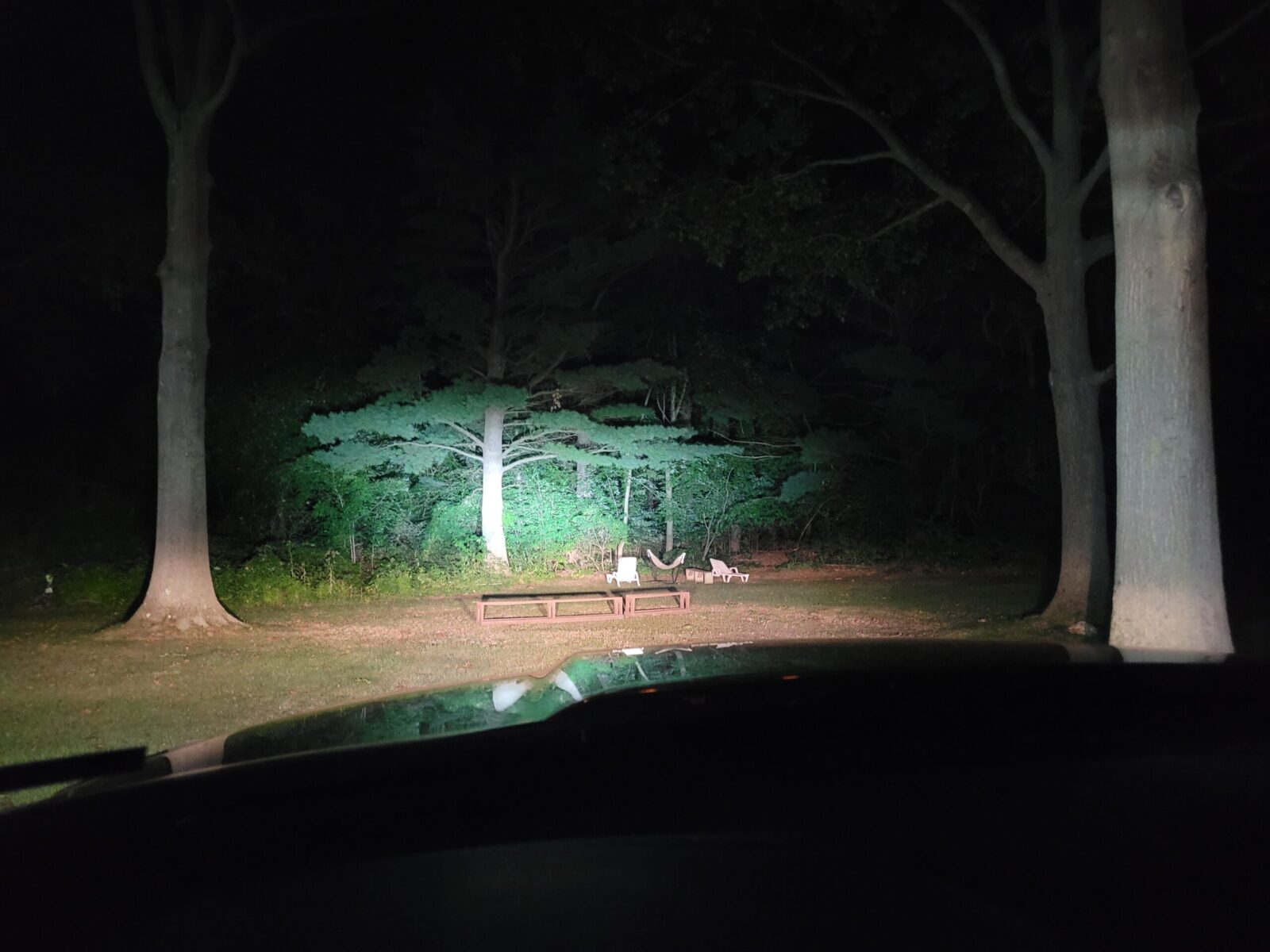
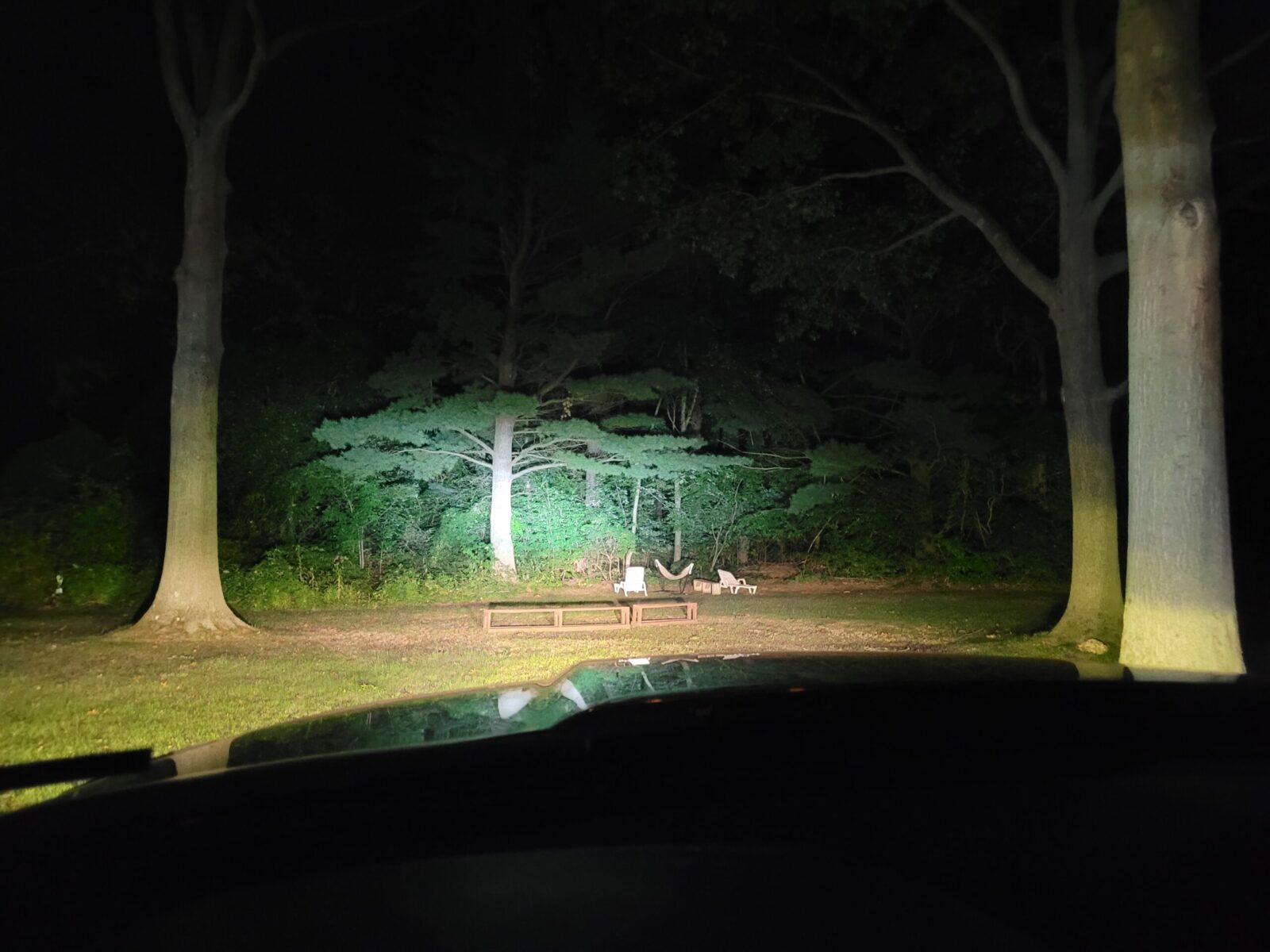
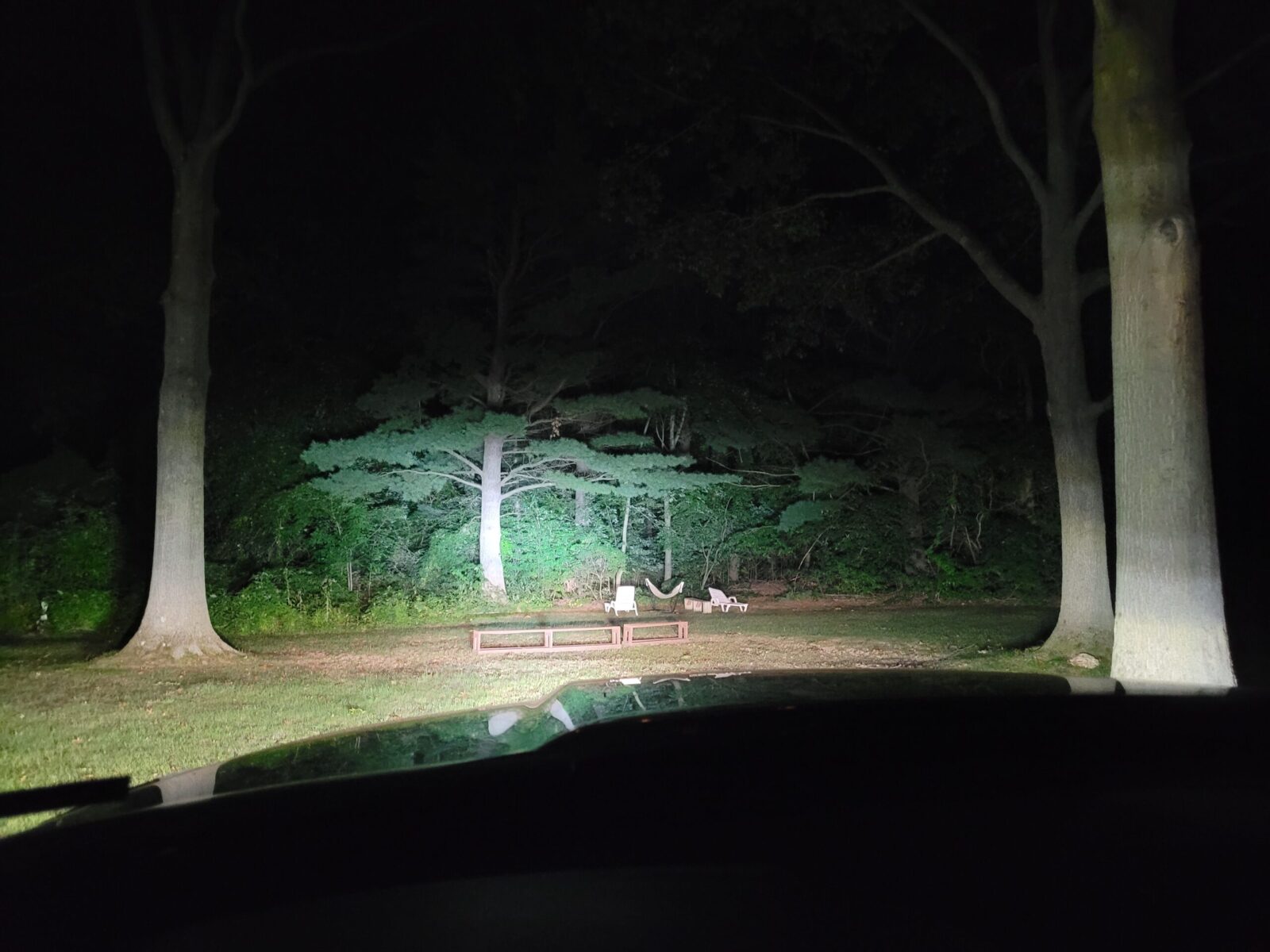
Low beam – these are the stock halogens.
High beams – Lasfit LED upgrade
High beams and new Nilight 20″ yellow fog light bar turned on.
High beam, yellow fog and 26″ light bar all on. What you can’t see in this photo is that peripheral light increased dramatically. If you were on a trail and wanting to see a deer or something coming in from the side, it’s a definite improvement. Just to be clear though, this is not street legal.
Here’s a video of the testing:
This really helps you see the results.
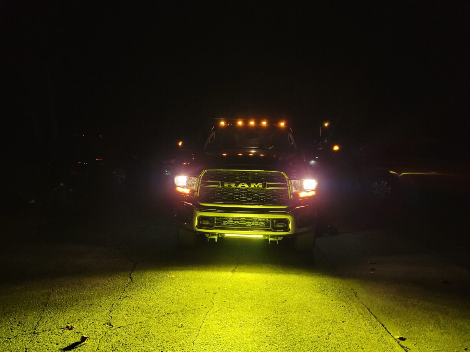
Here’s looking at the truck with low beams on and the yellow LED bar. I really like how it lights the road up directly in front of the truck. You can see the clocking issue I mentioned because the amber light bar is slightly lower on the right than on the left.
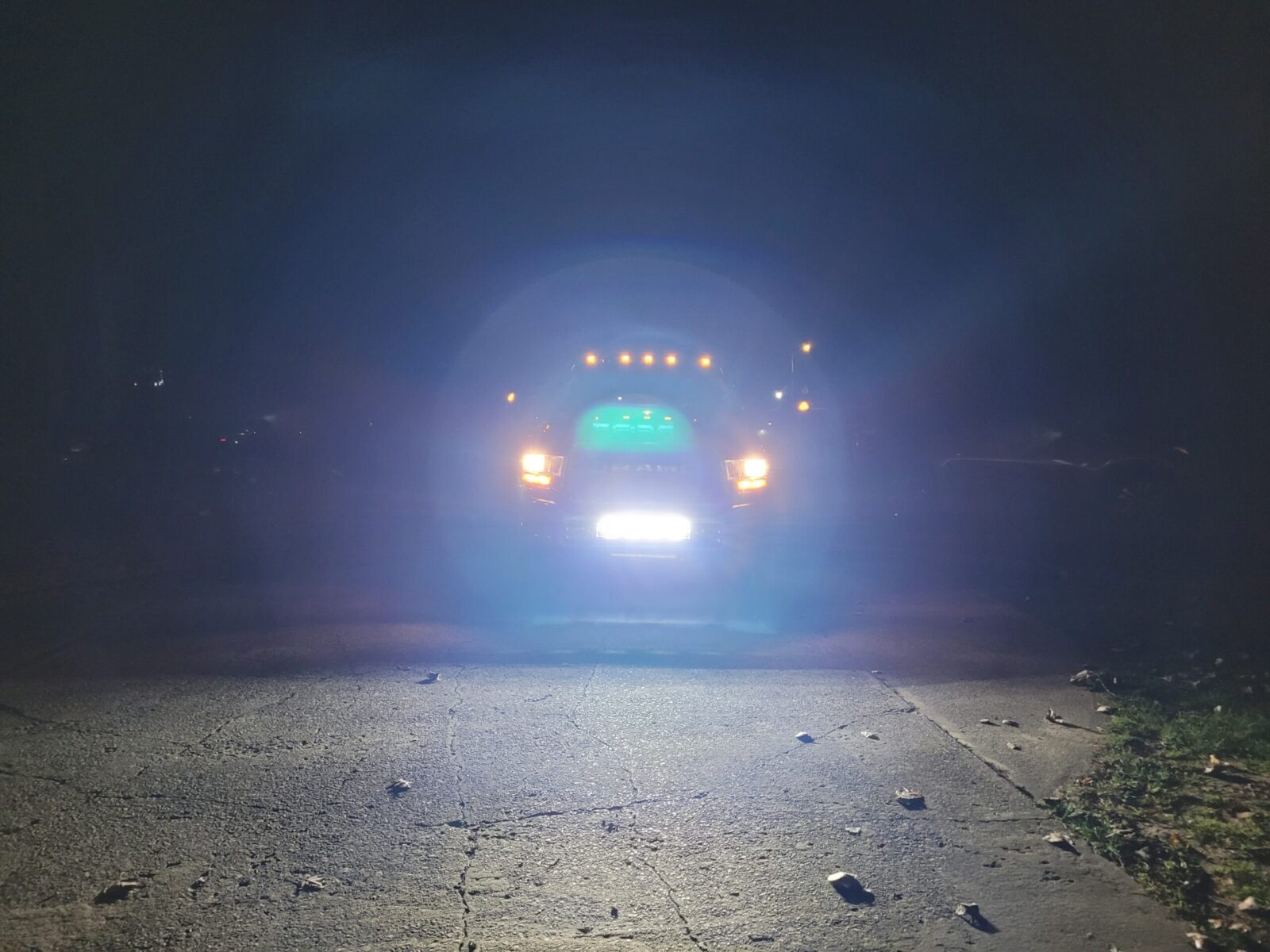
Oh man, do not run that 26″ bar on the road. It is like looking at a camera flash going off continuously. It’s incredibly bright and will blind anyone looking at it. It took a few minutes for my vision to come back after quickly snapping this photo.
From a distance you really don’t see the lights blatantly there – you have to look for them.
You get in closer and you can see them but you have to be looking for them.
Conclusion
I like how things turned out. I’ve been using the set up for about a month now and am very happy. I’ll post updates down the road. Lighting may look daunting but it is actually quite straight forward. Nilight is a cost effective way to get started.
I hope this helps you out!
4/7/24 Update: Everything has held up just fine – no problems of any kind since I installed them.
Note, I have to buy all of my parts – nothing here was paid for by sponsors, etc. I do make a small amount if you click on an ad and buy something but that is it. You’re getting my real opinion on stuff.