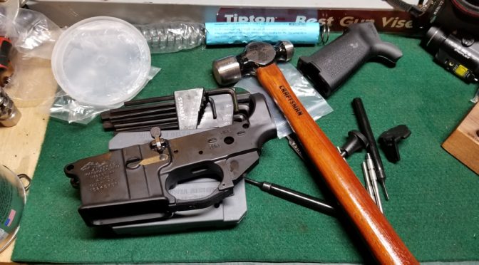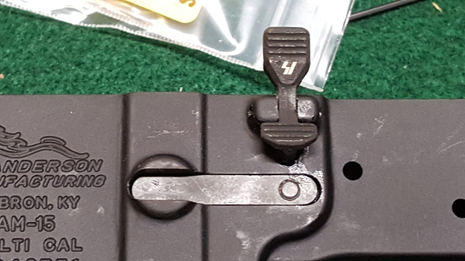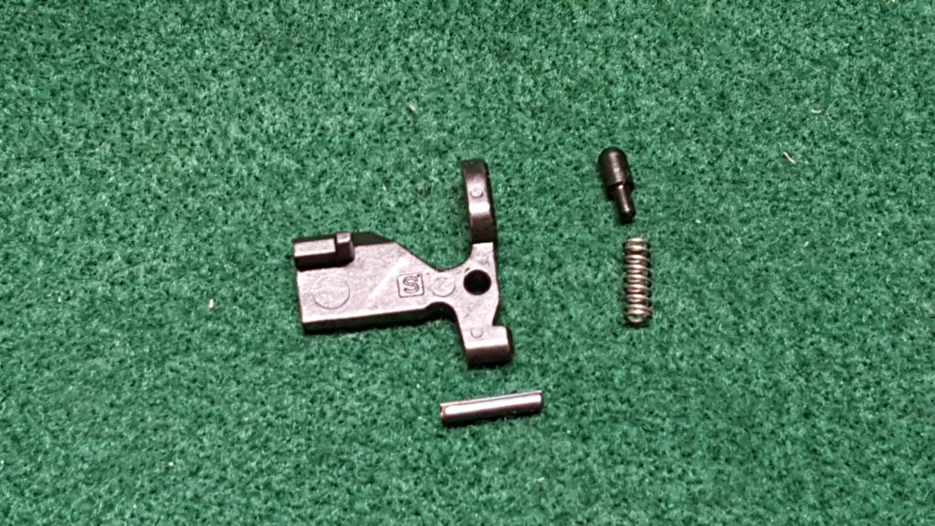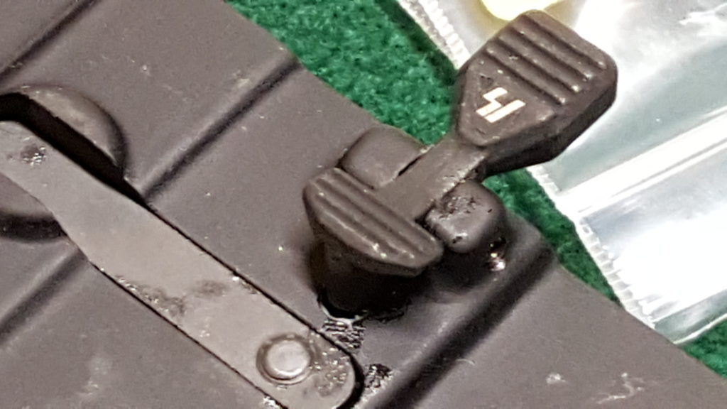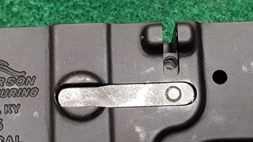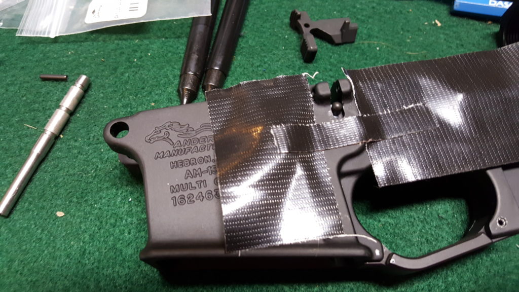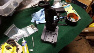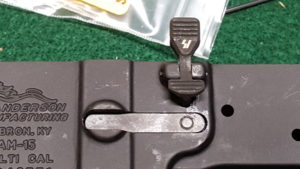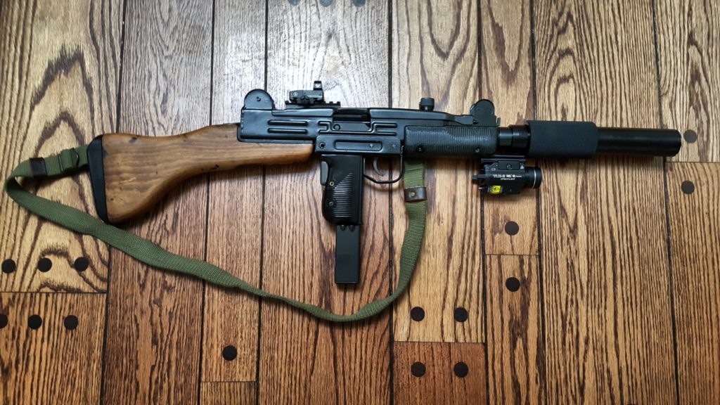
So the semi-auto 9mm Uzi carbine build has the Molyresin applied and is ready to go together. The following is an overview of the final assembly steps:
1] Install the grip frame assembly. Insert the tip first and swing the back up into position. Install the grip frame takedown pin. If the assembly will not go into position you may need to remove the bolt safety. The McKay receiver and bolt do not use that part. If you have questions about the grip assembly and preparing it for semi-auto use, click here.
2] Install the stock bracket with its 1/4″ screw and then the stock itself with its three screws taking care to use the correct bit on the slotted screws. Make sure the bolt doesn’t stick in too far. If you have questions about converting the quick detach stock to be permanently attached, click here.
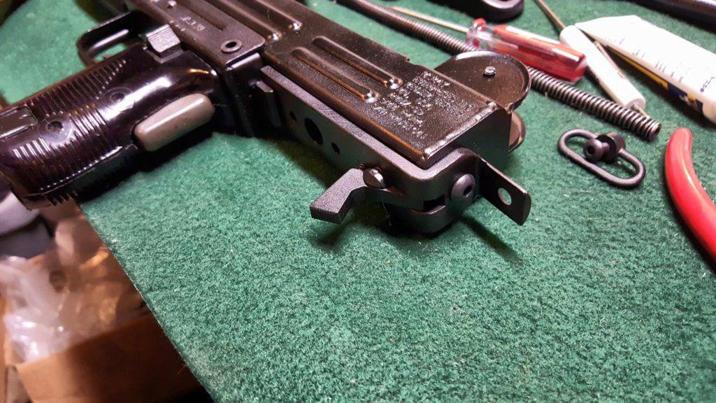
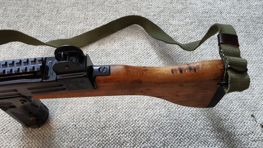
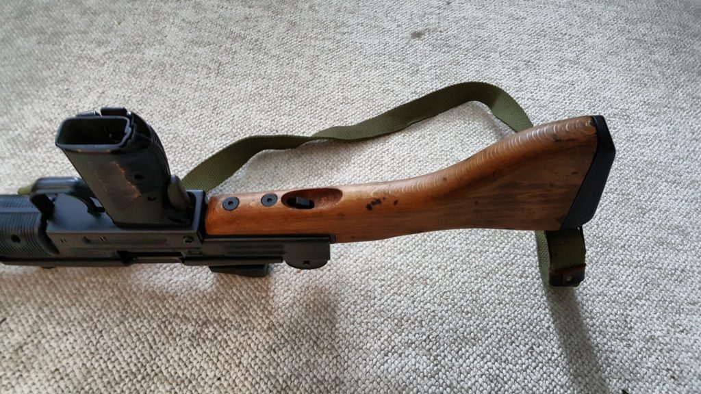
3] The handguards are installed with the two screws. I did my initial build with the beat up originals but then purchased a new set from US Barrel Shroud that isn’t shown in these photos.
4] I installed the barrel nut catch and spring plus the front sight. Slide the catch far enough back that it hooks the receiver and does not come back out.
5] I then installed the rear top cover catch and rear sight. The trick here is to push down on the flip sight while pushing the screw through so the threads can engage on the other side. The little tiny but just locks it in place – the receiver itself is threaded also. Note, I did have an issue with either the thread on the bolt or the receiver. I could not get the rear sight screw to enter on the opposite threaded side. After playing with it for a few minutes it dawned on me that either the screw or the threading in the “ear” of the receiver could be messed up so I installed the screw from the opposite direction just to chase the threads real quick and that solved whatever the problem was because when I then tried to insert it the correct way, the screw went right in.
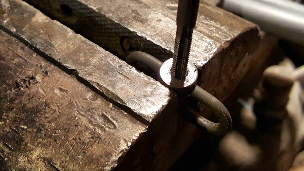
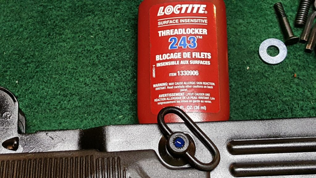
6] Rather than mess with rivets, I tapped the front sling for a #10-28 screw. I sanded down the head of the screw to avoid interference with the bolt and then applied medium Loctite to the thread when i installed it. If you need to remove more of the screw head later it can be readily reached with a Dremel and a flap sander or whatever bit you wish.
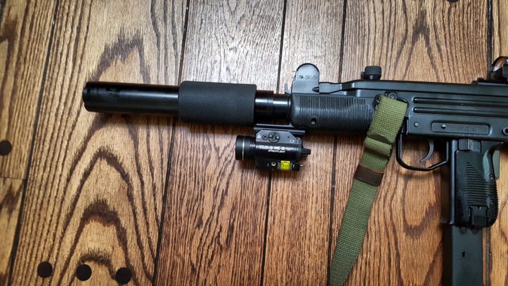
7] The 16″ semi-auto barrel slide right into the front trunnion and into the ring of the semi-auto feed ramp. Rather than use the barrel nut, I opted for a very cool two piece barrel shroud from Title II Arms. It is solid aluminum and exceptionally well made. Note, I show a light on a rail adapter on the bayonet lug. It looks cool but I actually removed it as my hand’s natural hold runs right into it. It’s not a reflection of the CAA rail but it’s just not for me. With it gone, my hand can go right out to the end of the handguard and is much more comfortable.
8] Next it was time to sort out the striker fired bolt system. This raises a critical legal point –the weapon must fire from a closed bolt. This means you can’t use the original open bolt. After some digging, I decided to use the McKay closed semi-auto bolt system for my build. Now McKay components are popular and they were out of stock on the complete bolt assembly but Robert RTG had it in stock so I bought it and other parts from them. As of my writing this, for example, McKay has their receivers in stock, bolt assembly but not the barrel so you can check between both firms plus McKay says they sell to Sarco and Apex.
9] I had to do some reading to figure out how the bolt went together as I had never seen anything quite like it before. The best write-up I could find that really helped me is right here. In a nut shell, take your original bolt, push out the extractor retaining pin and then push the extractor straight out the front of the bolt. From the rear, the extractor looks like a screw due to the slotted head but it is not. The slot is there to make it easy for you to rotate the extractor into position. Insert the extractor into the new semi-auto bolt. You will notice that with your semi-auto bolt a small blocking latch and pin are included just like you would see in the Uzi Pro Pistol – indeed, the whole bolt assembly is very similar to the Uzi Pro Pistol if you look it up. The little spring and the latch are inserted into the bolt and held in place by the extractor pin in the semi-auto bolt.
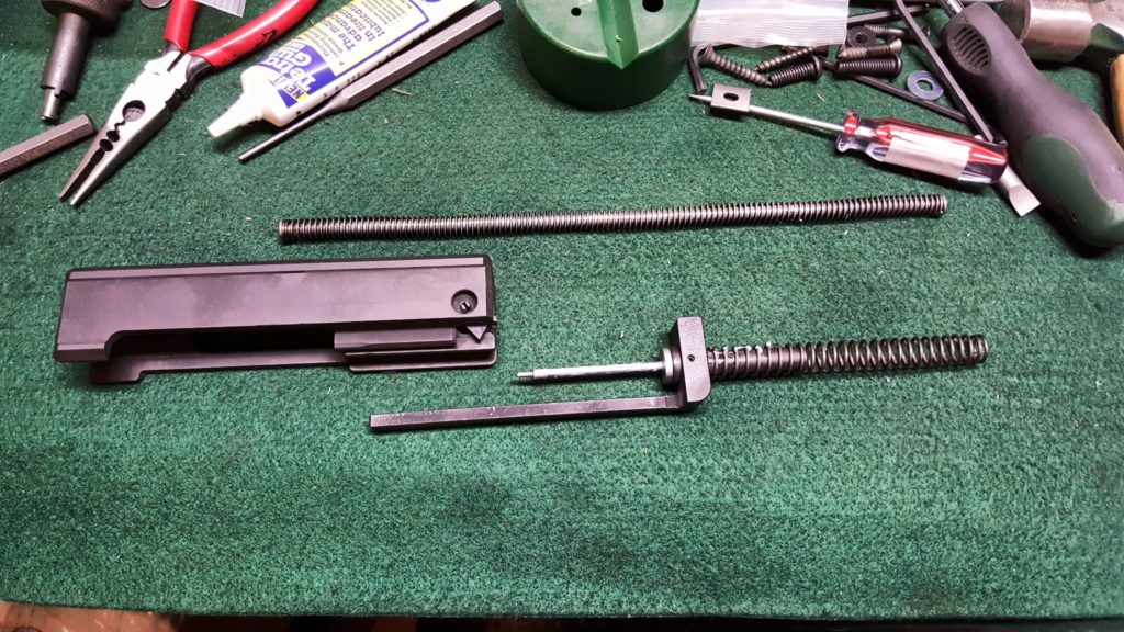
Ok – this next photo shows a problem that I didn’t find out until the first trip to the range. At the lower right of bolt is a pin that holds the extractor in place plus you can see a tab sticking down – that is the locking latch. Now look at the striker. You can’t see clearly but it is a half moon shape and I have it installed backward. The notch, or part of the striker’s base that is missing should be what goes against the bolt blocking latch. If you get it backward the weapon will not fire and you’ll notice the striker base getting beaten up by the latch.
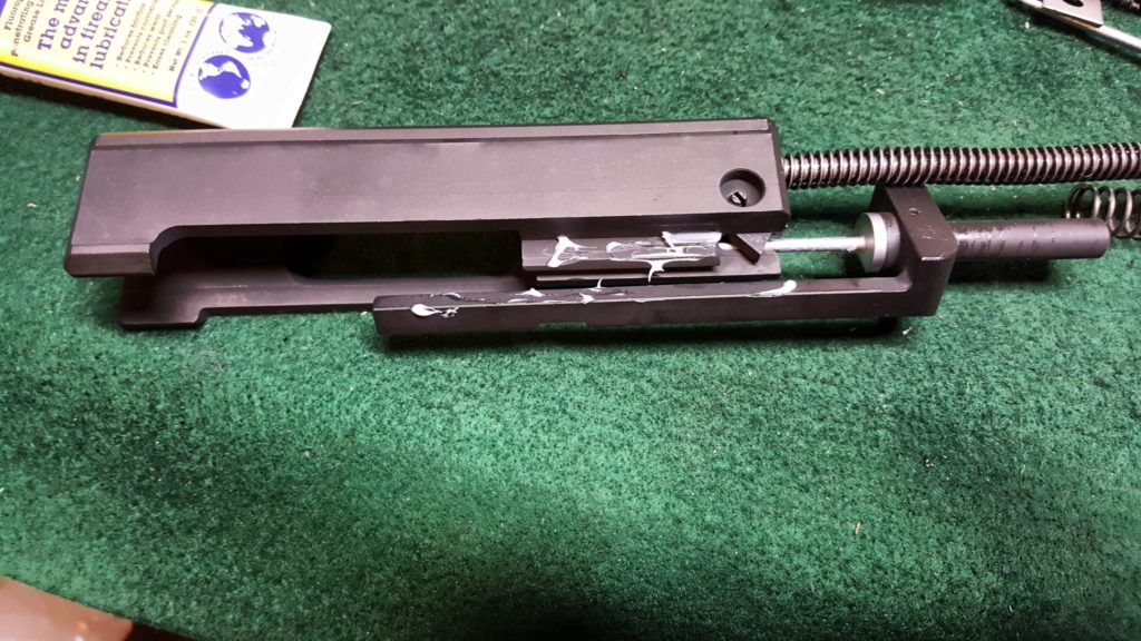
Here’s the blocking latch – see how the bottom part stocks out? That is what will need to clear the notch when it is depressed during normal operation.
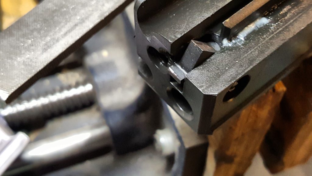
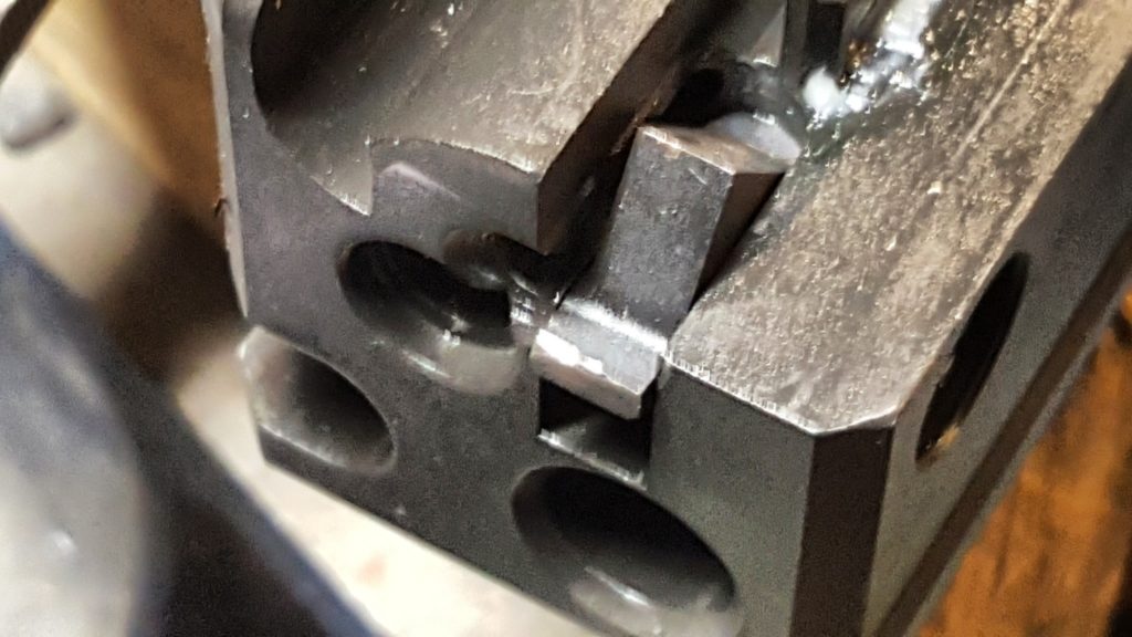
Here’s what it should look like – note how the striker bar has a smooth side and one with a relieved/depressed surface? The notched striker base goes towards the smooth portion:
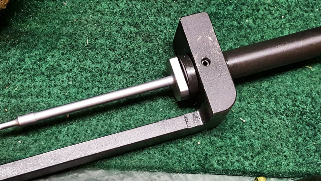
Here you can see the base that is towards the relieved/depressed area plus you can see the blocking latch will let the striker come forward only if the latch is depressed. The chewed up area on the striker is from my mistaken assembly and a ton of testing trying to figure out what I did wrong.
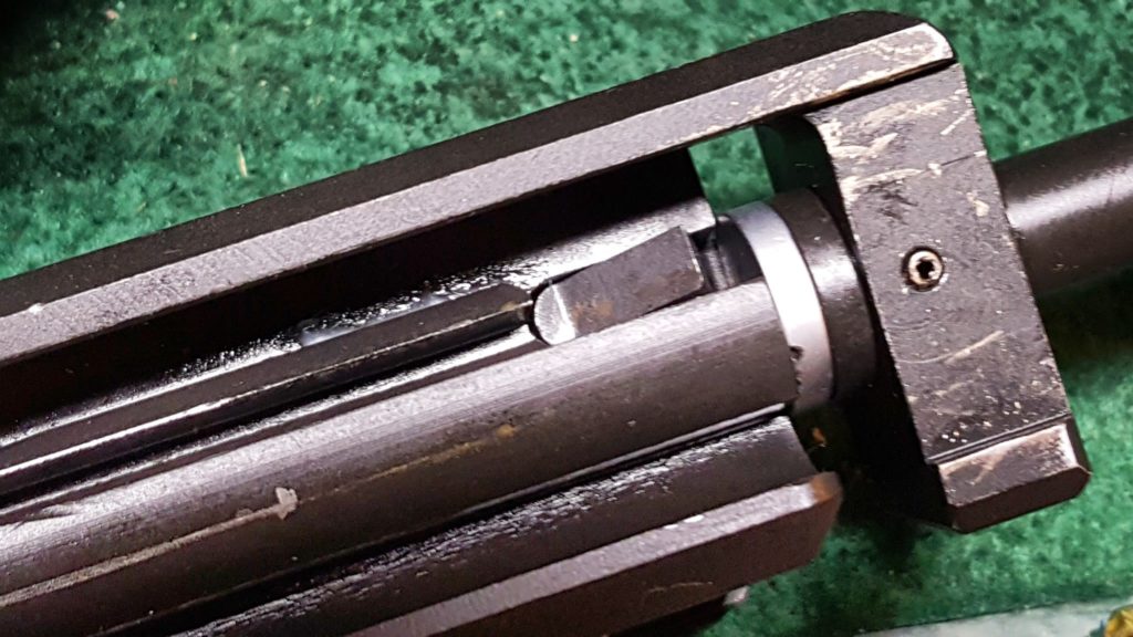
Here’s another angle. The striker can only travel forward if that blocking latch is depressed – in the photo, the latch would be pushed down out of the way. In the Uzi with the bolt oriented the normal way, we would say the latch is being pressed upward.
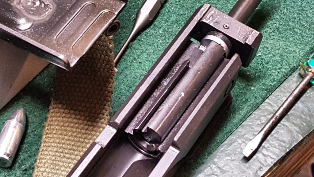
Last pic:
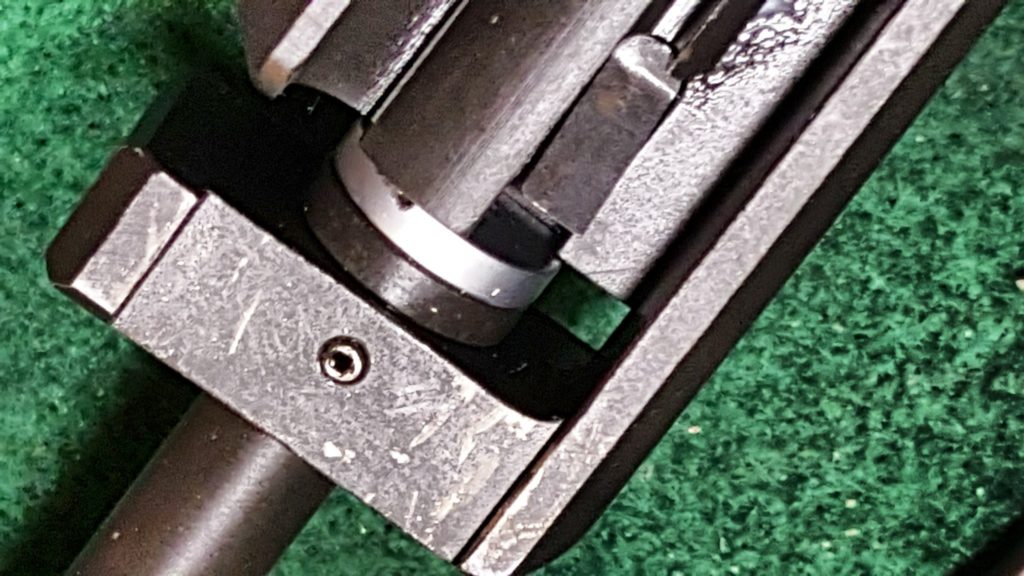
10] If you look at the above photo, the striker system. The lower L-shaped bracket is the “Striker Guide”. Thestriker spring base and the striker are held in place by a roll pin. The return spring slides over the striker spring base as shown above.
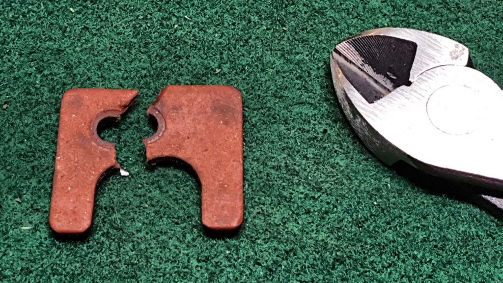
11] Take the guide rod and spring from the kit and snip the fiber square board off the end. I used diagonal cutters and when I made my first cut the little board fell right off.
12] You then insert the recoil spring into the bolt and rotate the firing pin base while inserting the assembly into the bolt. The white is Tetra Firearm Grease. If it slides, grease it. If it rotates, oil it. You want this system to be well lubed to help it wear in.
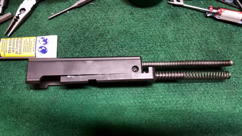
13] Here is the whole bolt assembly with the recoil buffer at the end. Now this assebly is slid into the Uzi buffer end first. It takes some maneuvering to the recoil block into the rear and then the bolt nestles down.
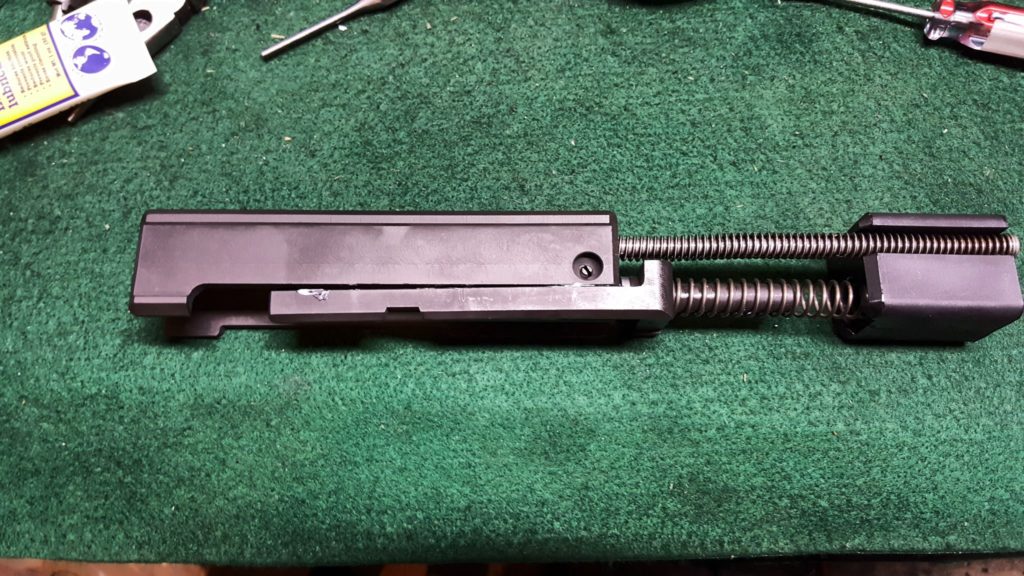
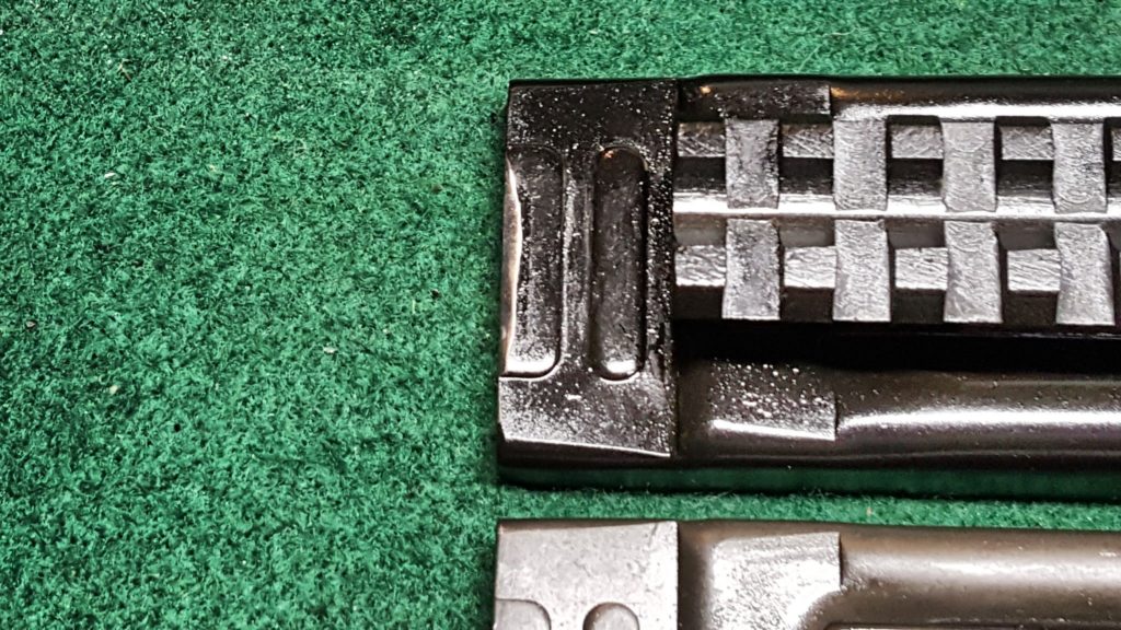
14] The top cover is then installed. I used a 120 grit flap sander bit to slightly bevel my top cover to the catch can close and the top is really tight. The top black cover has the bevel in the photo below – it doesn’t take much. If you have any questions about what needs to be done to prepare the top cover for semi-auto use, click here.
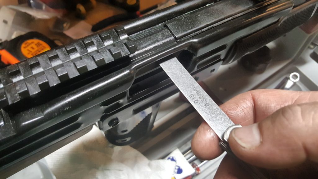
14.1 – Added 7/2/18: I found out that you really need to fit the top cover. If you take a feeler gauge, you should be able to insert a 0.005 gauge between the bolt body and the top cover at the ejection port and meet little to no resistance. However, if you insert a 0.015 gauge, you should feel some resistance – not a complete stop but firm resistance. At 0.005, the gap is too small and you risk the bolt body binding and not travelling fast enough or far enough resulting in ejection and feed problems. The cover is very easy to adjust. I did a more detailed blog about testing and adjusting the cover – click here.
15] Now function test it to be safe. Do this with the weapon unloaded!!
- Try to move the selector switch to Full Auto, which is all the way forward. It must not be able to move past semi-auto. If it does slide to the forward full auto position, you must fix it. If you haven’t done so, you need to install or fix your blocking tab that should be welded in the grip frame – click here for details. If you welded in a blocking plate, it may be too thin or too short. Regardless, you must figure out what is going on and fix it immediately. The ATF says the selector must not move into the full auto position.
- Move the selector to semi-auto (the middle position), hold the grip safety, cock the weapon and squeeze trigger – you should here it dry fire with a real solid clunk sound. Life is good. If there is a soft click, the striker system did not cock – check your sear to make sure it is protruding into the receiver.
- Move the selector to semi-auto (the middle position), DO NOT hold the grip safety, cock the weapon and squeeze trigger – the weapon should not fire. The Uzi should only be able to fire if on semi-auto and the grip safety is held. Check your pins and that the grip safety bar is sliding properly.
- Move the selector to safe (all the way to the rear), hold the grip safety, cock the weapon and squeeze the trigger – the trigger should be blocked and nothing should happen. Turn the safety off and the weapon should fire. If it does not, check the pins and the selector bar can move into position properly and block the trigger.
- Last, move the selector to semi-auto, hold the grip safety, squeeze the trigger (do not release it) and cock the weapon while holding the trigger in. We want to ensure the disconnector grabs the striker assembly. Now, release the trigger and squeeze it like normal. You should here it dry fire with a loud clunk sound and that is what you want. A light click is just the trigger and disconnector moving around and means the striker went back into battery vs. being retained. Something is off with the geometry – something is bent, you forgot to secure the grip frame with the takedown pin, etc.
If your Uzi passes the function tests, then proceed to test firing. I’d recommend securing the carbine in a stand and test firing with a string vs. holding the weapon. Also, only load one round in the magazine at a time and inspecting the carbine, especially the barrel, to make sure the first round fires and the case is ejected. Look for dings or tears in the case. Make sure the bullet didn’t get stuck in the barrel. If things are looking good, put two rounds in the magazine and test the overall cycling of the weapon. Again, check the case for any big gouges, scrapes, etc. When you are satisfied that the weapon is functioning correctly, then and only then try more and more rounds of ammo. I would go from one, to two, to three to five and to 10 before I tried a full clip. You do not want to have an uncontrolled full auto dump happen so carefully test the Uzi.
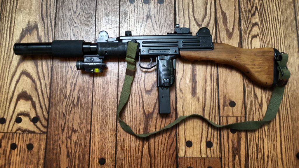
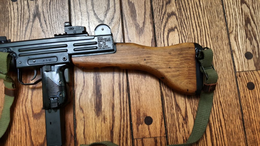
I had a lot of fun building mine. I added a Vortex Venom red dot that I really like so far plus an original Uzi green sling. Here are some photos and as mentioned the light and rail are off the weapon at this point.
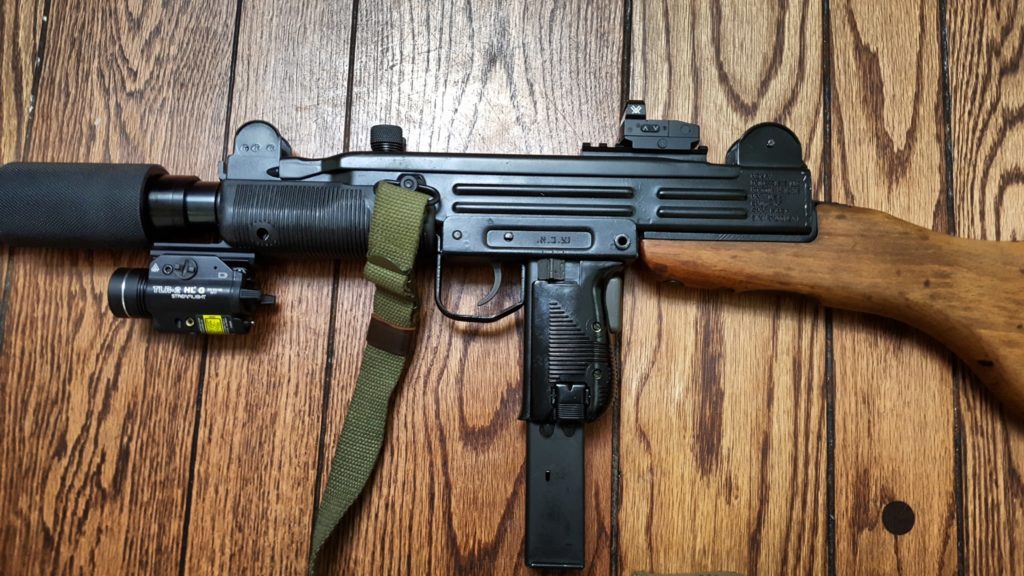
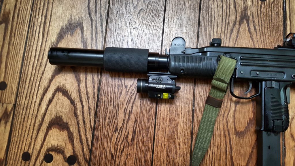
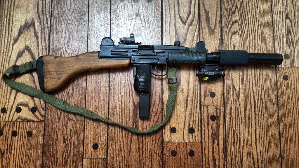
I hope this helps and if you have any suggestions, please let me know.
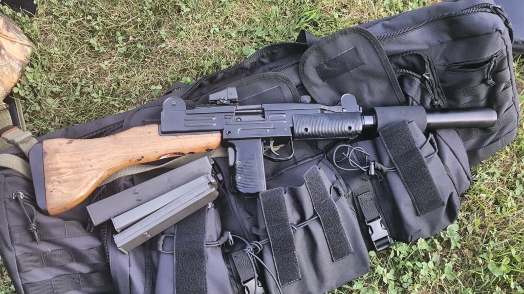
7/2/2018 Update – I did get rid of the light/laser on the front. It was in the way of my hand. I also have some recommendations to double check in case your Uzi has any problems firing – click here.
If you find this post useful, please share the link on Facebook, with your friends, etc. Your support is much appreciated and if you have any feedback, please email me at in**@*********ps.com. Please note that for links to other websites, we are only paid if there is an affiliate program such as Avantlink, Impact, Amazon and eBay and only if you purchase something. If you’d like to directly contribute towards our continued reporting, please visit our funding page.
Like this:
Like Loading...


